

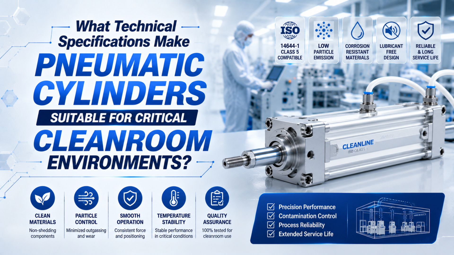
A pneumatic cylinder is suitable for a critical cleanroom when the exact model and configuration have particle, material, lubrication, cleaning, and motion evidence that matches the installed application. ISO 14644-1 room classification, stainless-steel construction, a non-lube label, or a generic “cleanroom ready” statement cannot establish that suitability by itself.
Cleanroom pneumatic cylinder specifications should therefore describe the evidence boundary as carefully as the hardware. A bore, stroke, and material list is not enough.
The strongest specification connects five boundaries: the process limit, the cylinder part number, the operating envelope, the test method, and the maintenance state. If one boundary is missing, the claim is incomplete.
Key Takeaways
- ISO 14644-1 classifies airborne particle concentration in a cleanroom or clean zone; it does not certify cylinders by product category.
- ISO 14644-14:2026 is the relevant equipment-suitability framework for airborne particles, but it does not prescribe cylinder materials or prove cleanability, chemical suitability, or biocontamination control.
- Ask for model-specific particle data tied to mounting position, speed, load, pressure, cycle count, suction condition, particle size, and sampling geometry.
- Treat seals, grease, surface finish, cleaning chemistry, compressed air, exhaust routing, and packaging as separate specifications.
- Qualify cleanliness and pneumatic performance together on the installed machine.
What Does “Suitable for a Critical Cleanroom” Actually Mean?
ISO 14644-1 classifies air cleanliness by the concentration of airborne particles at designated sampling locations. Its classification range covers threshold particle sizes from 0.1 µm to 5 µm, and it does not characterize the chemical, viable, radiological, or physical nature of those particles (ISO 14644-1, 2015).
That distinction prevents a common procurement error. An ISO 5 room requirement describes the controlled environment. It does not automatically impose one material recipe on every cylinder inside the room. Nor does it mean that a cylinder can be called “ISO 5 certified” without an equipment test and a defined installation boundary.
Cleanroom suitability is the documented ability of a named cylinder configuration to meet a stated cleanliness limit under recorded operating and sampling conditions. The statement should identify the following:
A cleanroom cylinder specification is a controlled description of the process target, hardware identity, operating envelope, test evidence, and lifecycle state. The room class sets an environmental limit. The supplier report describes a tested component. The machine drawing fixes its position and nearby release paths. The motion profile adds pressure, speed, load, impact, and cycle conditions. Finally, the maintenance plan controls seals, grease, cleaning, replacement parts, and changes after acceptance. These layers should remain separate because passing one does not prove the others. Written this way, “cleanroom ready” becomes a verifiable procurement statement: the buyer can see what was tested, where engineering inference begins, and which gaps still require installed qualification.
| Claim element | Minimum information needed |
|---|---|
| Process limit | ISO class or concentration limit, particle size, chemical or viable boundary, and critical location |
| Hardware identity | Manufacturer, complete part number, bore, stroke, options, seals, grease, sensors, and production revision |
| Operating state | Mounting position, pressure, speed, acceleration, load, moment, cycle pattern, temperature, and suction flow |
| Test method | Chamber or installed test, background level, counter, probe position, sample duration, cycle count, and data treatment |
| Maintenance state | New, run-in, end-of-interval, cleaned, relubricated, or rebuilt condition |
The word “critical” also needs a process definition. Semiconductor lithography may prioritize airborne molecular contamination, ionic residues, silicone restrictions, and electrostatic behaviour. Aseptic filling adds viable contamination, cleaning, disinfection, airflow, and exposed-product risks. Medical-device assembly can have another set of material and surface requirements. One cylinder label cannot replace those process-specific acceptance criteria.
For the broader pneumatic chain, including valves, tubing, fittings, and exhaust, use the guide to selecting Class 100 cleanroom pneumatic components. This article stays focused on the cylinder specification and its evidence package.
Which ISO Standards Apply to a Cleanroom Pneumatic Cylinder?
ISO 14644-14:2026 provides a method for assessing equipment, components, and tools for use in cleanrooms with respect to airborne particle concentration. It covers particle sizes from 0.1 µm to 5 µm and above. Its scope explicitly excludes biocontamination, cleanability, decontamination methods, equipment design, material selection, process-performance optimization, and local safety requirements (ISO 14644-14, 2026).
The exclusion list is important. It means a particle-suitability result does not prove that a cylinder tolerates vaporized hydrogen peroxide, that its external surfaces are easy to disinfect, or that its seals meet a pharmaceutical material policy. Those require separate evidence.
ISO 14644-15:2026 addresses equipment and material suitability by airborne chemical concentration. It is linked to the chemical cleanliness framework in ISO 14644-8, but it also excludes cleanability, cleaning-agent compatibility, biocontamination, product-specific requirements, and equipment design (ISO 14644-15, 2026).
Use the standards as separate evidence boundaries:
| Question | Relevant framework | What it does not prove by itself |
|---|---|---|
| What is the room’s airborne particle class? | ISO 14644-1 | Cylinder suitability or chemical cleanliness |
| Does the operating cylinder fit a particle limit? | ISO 14644-14 | Material selection, cleanability, or biocontamination control |
| Does equipment or material fit an airborne chemical limit? | ISO 14644-15 and ISO 14644-8 | Cleaning compatibility or process-specific product safety |
| What particles, water, and oil are in the compressed air? | ISO 8573-1 and its test-method parts | Room-air class or sterile-process approval |
ISO 8573-1 classifies compressed-air purity for particles, water, and oil independently of where the air is specified or measured. It also identifies gaseous and microbiological contaminants (ISO 8573-1, 2010). Write this requirement at the cylinder or point of use. A compressor-room result may not capture contamination added by distribution piping, condensate, filters, tubing, valves, or maintenance.
Which Particle-Generation Specifications Should You Request?
Request a test report for the quoted cylinder rather than a cleanroom class printed without conditions. A useful report ties the measured result to the complete model and motion profile.
At minimum, record:
- complete part number, bore, stroke, mounting orientation, sensor configuration, and tested sample quantity;
- pressure, speed, acceleration, payload, side load, moment, cushioning, and cycle pattern;
- grease, seal system, guide construction, relief or vacuum-port state, and suction flow;
- chamber volume, background particle concentration, supplied-air quality, particle counter, minimum particle size, sampling flow, probe position, and test duration;
- number of cycles before and during measurement, run-in condition, maintenance state, statistical treatment, uncertainty, and measured result;
- statement of whether the data are guaranteed, typical, representative, or for selection reference only.
Model-specific particle evidence is a test result that remains traceable to the exact cylinder and the conditions that produced it. It should identify the order code, sample condition, particle sizes, chamber or room background, counter, probe position, sampling flow, operating pressure, speed, load, cycle count, mounting position, and relief or suction state. It should also explain how the result was calculated and whether it is guaranteed or representative. Without those fields, two attractive particle numbers may describe different volumes, time intervals, test states, or statistical treatments and cannot be compared. Procurement teams should record missing fields as qualification gaps instead of silently assuming that a product-family statement covers the quoted configuration.
SMC’s clean-series catalog illustrates why these fields matter. Its published particle test places a sample in an acrylic chamber inside an ISO Class 5-equivalent clean bench, supplies clean air, and uses a light-scattering particle counter with a stated sampling method. The catalog also says its particle-generation plots are representative rather than guaranteed (SMC Clean Series catalog, accessed 2026).
That evidence is useful because its conditions are visible. It should not be converted into “all clean cylinders generate fewer than a fixed number of particles per stroke.” Per-stroke counts, chamber concentrations, equipment-suitability classes, and room classifications are different quantities. Do not compare them until the particle sizes, volumes, sampling time, background correction, operating state, and acceptance calculation are aligned.
Installation position can change the required evidence. Festo notes that cleanroom suitability depends primarily on product position and operating parameters (Festo cleanroom guidance, accessed 2026). A cylinder below a guarded workpiece may have a different risk than the same model moving above exposed product in the protected airflow.
Which Cylinder Design Features Control Particle Release?
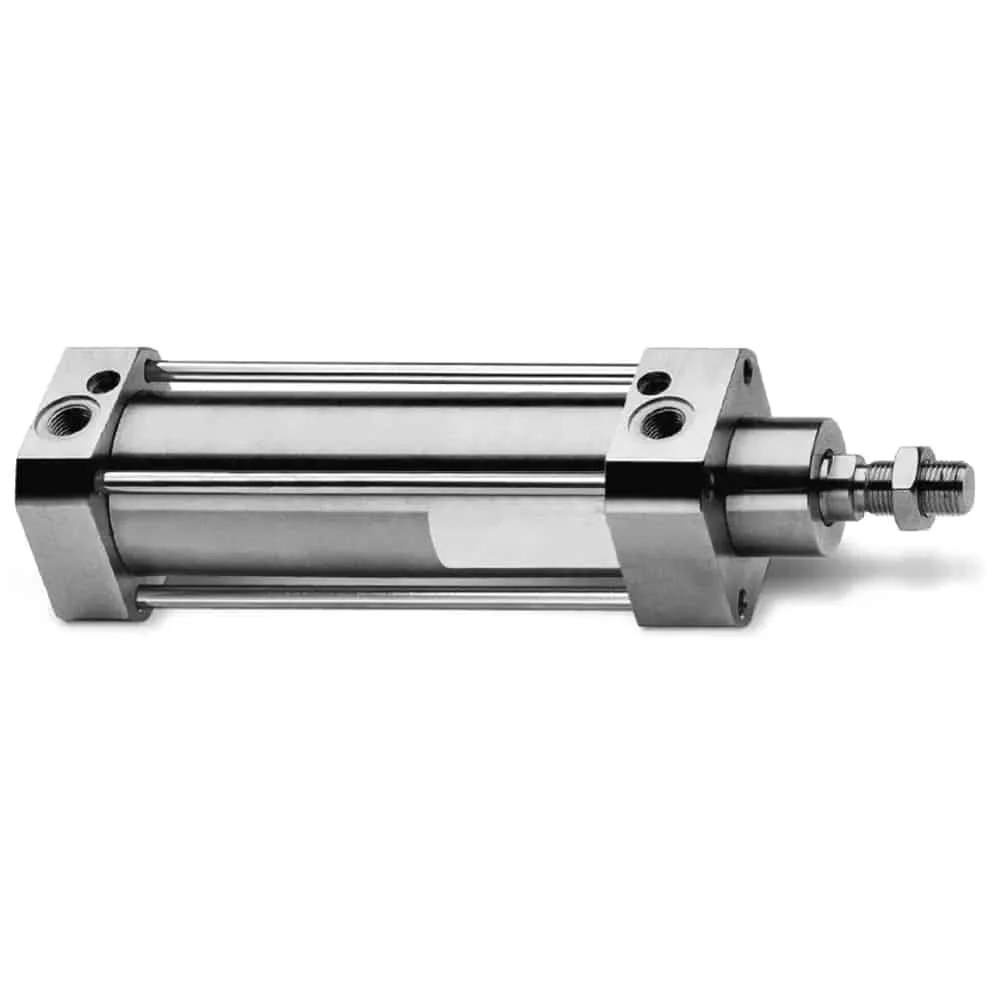
A cleanroom cylinder manages release paths; it does not eliminate wear. Rod seals, wipers, piston seals, guides, bearings, bumpers, magnets, cushioning parts, cable jackets, and external fasteners can all affect the result.
Relief and vacuum-suction ports
Some clean cylinder families use a double-seal arrangement and route leakage or generated particles through a relief port. Higher-control variants can connect the port to vacuum suction. The required suction flow and tube restriction are part of the clean configuration, not optional installation details.
For example, SMC’s CQ2 clean-series catalog separates relief and vacuum-suction types and lists model-specific reference suction flows. It also gives different particle-generation grades, grease systems, piston-speed limits, and operating conditions for its option codes (SMC CQ2 clean-series catalog, accessed 2026).
When reviewing this design, ask:
- Which seal cavity connects to the port?
- Is discharge permitted into the room, or must it be routed outside the critical zone?
- What minimum suction flow is required at the cylinder while it is cycling?
- What tubing length, diameter, filter, and vacuum pressure were used in the particle test?
- How will loss of suction be detected?
A vacuum port without verified flow is only an unused hole. An undersized line, clogged filter, or failed pump can invalidate the release-control mechanism.
Rod, rodless, and guided construction
A conventional rod cylinder concentrates sliding contact at the rod seal and wiper. A mechanically coupled rodless cylinder adds a longitudinal slot and sealing bands. A magnetically coupled rodless cylinder closes that slot but still has external guide and carriage wear. A guided cylinder adds bearings that control side load but introduce more contact surfaces.
Choose the architecture from the combined load and cleanliness risk. If an external guide is required, put its allowable force and moment on the RFQ. Side load can increase seal and bearing wear even when nominal thrust is adequate. The high-speed cylinder specification checklist explains why speed, kinetic energy, cushioning, alignment, and mounting must be reviewed together.
Are 316L Stainless Steel and Ra 0.4 µm Always Required?
No. ISO 14644-14 does not prescribe 316L, electropolishing, or a universal surface roughness. The material decision should follow the cylinder’s location, cleaning chemistry, corrosion exposure, residue risk, and accessibility.
An anodized aluminium cylinder can be acceptable in a dry, non-product-contact position when particle evidence and cleaning controls fit the application. Stainless steel may be justified for repeated chemical cleaning, exposed product zones, corrosion risk, or facility material policy. Even then, specifying only “316L cylinder” is incomplete. Rods, end caps, tie rods, fasteners, sensor rails, labels, bumpers, fittings, and mounting hardware may use other materials.
Electropolishing can improve the passive condition of stainless surfaces, but it does not automatically produce one roughness value. ASTM B912 covers stainless-steel passivation using electropolishing; a numeric Ra requirement still needs to be placed on the drawing with its measurement method and locations (ASTM B912, accessed 2026).
Use this material specification sequence:
- Name the exposed process and cleaning agents, including concentration, temperature, contact time, frequency, rinse, and drying state.
- Identify which cylinder surfaces sit in the critical zone and which are shielded.
- Specify metal grade, coating, surface finish, seal compound, grease, adhesive, cable jacket, and restricted substances only where the risk supports them.
- Request compound-level compatibility and test evidence rather than relying on a polymer family name.
- Define acceptance after repeated cleaning, including swelling, cracking, corrosion, discoloration, residue, particle change, leakage, and loss of motion performance.
The guide to actuator seal compatibility in chemical environments covers the separate task of matching an exact seal compound to the real exposure sequence.
How Should Seals, Grease, and Lubrication Be Specified?
“Non-lube” normally means that added airline oil is not required. It does not necessarily mean grease-free construction. A factory-lubricated cylinder can still contain grease on seals and sliding surfaces. The exact formulation, amount, application process, and replacement rule may affect particles and airborne chemicals.
Do not write “PTFE, PEEK, FKM, or EPDM is USP Class VI” as a generic statement. Biological-reactivity evidence is compound- and specimen-specific, and its relevance depends on the contact pathway. USP General Chapter 88 addresses in-vivo biological response testing for plastics, elastomers, and other polymeric materials; it is not a cleanroom particle certificate for a complete cylinder (USP General Chapter 88, 2024).
The cylinder specification should state:
- seal and wiper compound codes, not only polymer families;
- factory grease name or controlled specification, application quantity or process, and restricted-substance status;
- whether additional airline oil is prohibited, permitted, or required;
- approved replacement seal kit and grease;
- cleaning-agent compatibility for the exact compound and exposure cycle;
- particle or chemical test status after service or relubrication;
- shelf-life, packaging, storage, and handling limits where supplied cleanliness matters.
For a deeper distinction between factory lubrication and cleanroom evidence, see The Non-Lube Cylinder Advantage in Cleanroom Environments.
Which Motion Specifications Must Remain Inside the Cleanliness Test Envelope?
A cylinder can meet a particle target and still fail the machine’s motion requirement. It can also meet nominal force while generating more wear particles at the actual speed, side load, or end impact. Qualify both outcomes under the same conditions.
| Motion specification | Performance risk | Cleanliness connection |
|---|---|---|
| Working pressure and minimum dynamic pressure | Insufficient force or stalled motion | Seal contact and leakage can change outside the tested condition |
| Piston speed and acceleration | Cycle-time loss, shock, or instability | Higher rubbing speed and impact can increase wear debris |
| Load, side load, and moment | Rod bending, guide wear, or binding | Misalignment raises seal and bearing contact stress |
| Cushioning and external stops | Excess kinetic energy or rebound | End impact can release particles and shorten seal life |
| Cycle pattern and duty | Heat buildup and premature wear | Burst operation may differ from the particle test profile |
| Temperature | Seal friction, leakage, and sensor limits | Grease volatility, polymer behaviour, and chemical emissions can change |
| Vacuum or relief flow | Added plumbing and energy demand | Capture performance depends on verified flow and backpressure |
Record actual pressure at the cylinder during motion rather than relying on the regulator setting. Include tube length, valve flow, fittings, point-of-use filters, remote exhaust, and simultaneous demand. These can change stroke time and pressure while also influencing the cleanliness boundary.
What Changes Between Semiconductor and Pharmaceutical Applications?
The same ISO room class can sit inside very different process risks. Start with the contamination pathway instead of assigning one universal “critical cleanroom” specification.
| Review area | Semiconductor or electronics emphasis | Aseptic pharmaceutical emphasis |
|---|---|---|
| Airborne particles | Product feature size, optical surfaces, yield, local airflow | Exposed sterile product and critical-zone monitoring |
| Airborne chemicals | Acids, bases, organics, dopants, silicone, ionic or molecular contamination | Product, disinfectant, lubricant, and residue compatibility |
| Viable contamination | Usually process-specific rather than defined by particle class | Microbiological control and contamination-control strategy |
| Surfaces | ESD, low shedding, residue and material restrictions | Cleanability, disinfection, inaccessible gaps and product exposure |
| Documentation | Model report, restricted-substance declaration, change control | Qualification protocol, traceability, cleaning, maintenance and requalification |
FDA aseptic-processing guidance associates Class 100, or ISO 5, with no more than 3,520 particles/m³ at 0.5 µm and larger near exposed sterile work. It also emphasizes sampling at locations with the greatest product risk during operations (FDA Aseptic Processing Guidance, 2004). That limit describes the critical area. It does not assign a universal particle count per cylinder stroke.
Do not cite FDA 21 CFR Part 11 as a cylinder compliance standard. Part 11 concerns electronic records and electronic signatures. It may apply to an electronic validation or maintenance record system, but it cannot prove the actuator’s particle, material, or motion performance.
What Supplier Evidence Should Be Included in the Purchase Package?
In our experience reviewing pneumatic-cylinder applications, we first ask for the exact tested part number and installation position. Those two fields quickly separate a useful report from a product-family claim. We then compare the clean-series supplement with the ordinary performance datasheet because clean variants can have different speed, grease, port, maintenance, or option-code limits.
Request evidence in four groups.
1. Identity and materials
- complete order code and drawing;
- bill of materials for exposed and pressure-retaining parts where required;
- seal, wiper, grease, coating, adhesive, sensor, and cable specifications;
- material certificates, restricted-substance declarations, lot traceability, and change-notification policy appropriate to the project.
2. Cleanliness performance
- model-specific airborne particle report and its ISO 14644-14 boundary;
- airborne chemical or outgassing report when the process has a defined chemical limit;
- raw or summarized results, background data, particle sizes, sample configuration, operating state, and report revision;
- explicit statement of exclusions and untested configurations.
ASTM E595 can be appropriate when a project specifically needs its high-temperature vacuum screening method. It should not be inserted as a universal cleanroom requirement. The standard states that the historical 1.00% TML and 0.10% CVCM values were screening levels for spacecraft materials, and that its results do not necessarily predict system contamination in service (ASTM E595, 2021 edition).
3. Pneumatic and mechanical performance
- proof, maximum, and minimum operating pressure;
- bore, rod diameter, stroke tolerance, breakaway behaviour, piston-speed range, and temperature limits;
- allowable radial load, moment, guide capacity, kinetic energy, cushion adjustment, and mounting instructions;
- leakage limits, expected maintenance boundary, and test condition behind any life claim.
4. Delivery and lifecycle controls
- cleaning and assembly condition;
- bagging, transfer, opening, storage, and shelf-life instructions;
- approved service kit, grease, tools, and work procedure;
- change-control notice for materials or manufacturing revisions;
- conditions that require supplier review or installed requalification.
Do not request documents only to make the validation package thicker. Every document should close a named risk or expose a qualification gap.
How Should You Qualify the Installed Cylinder?
A supplier chamber report is screening evidence. Installed qualification is acceptance evidence. The final machine changes airflow, mounting stress, exhaust direction, tubing, valve behaviour, load, speed, cleaning exposure, and access for maintenance.
Installed cleanroom qualification is the documented demonstration that the assembled axis meets its cleanliness and motion criteria in the position and operating state the process will actually use. It connects the component report to the real valve, tubing, exhaust, suction line, mounting, payload, airflow, cleaning state, and product exposure. The protocol should establish background conditions, test normal production and worst credible operation, record probe geometry, and verify pressure, stroke time, leakage, temperature, cushioning, and suction flow during the same run. It should also state which deviations are acceptable and which hardware, software, cleaning, or maintenance changes invalidate the result. This makes the acceptance boundary repeatable instead of depending on a supplier label.
Use this sequence:
- Freeze the cylinder part number, seals, grease, sensors, valve, fittings, tubing, exhaust or suction plumbing, mounting drawing, and motion profile.
- Define separate acceptance criteria for airborne particles, airborne chemicals, surface or viable contamination, and pneumatic performance. Record why any category is not applicable.
- Establish room and supplied-air background conditions with the machine at rest.
- Run normal production plus worst credible speed, load, pressure, cycle burst, startup, and suction-loss conditions.
- Place particle or chemical sampling probes at plausible release paths and the highest-risk product location. Record the geometry so the test can be repeated.
- Verify pressure, stroke time, load handling, repeatability, leakage, temperature, cushioning, exhaust backpressure, and suction flow during the same operating state.
- Repeat the relevant checks after run-in and near the planned maintenance boundary.
- Define deviation handling and requalification triggers before production release.
The installed result applies only to the frozen configuration. Moving the cylinder above the product, increasing speed, changing grease, replacing the valve, adding a silencer, changing a cleaning agent, or rerouting vacuum tubing can change the conclusion.
What Should a Cleanroom Cylinder RFQ Contain?
Use an RFQ that forces the application and evidence boundaries into the same table.
| RFQ field | Information to send | Evidence to request |
|---|---|---|
| Critical zone | Room class, product position, airflow direction, drawing and distance | Tested position and sampling geometry |
| Particle target | Particle sizes, concentration or equipment limit, room state and background rule | Model-specific report and operating envelope |
| Chemical target | Restricted substances, concentration limits and relevant test method | Chemical-emission or outgassing data for the delivered configuration |
| Cleaning | Agent, concentration, temperature, dwell, frequency, rinse and sterilization if applicable | Compound-level compatibility and surface evidence |
| Motion | Bore, stroke, load, side load, moment, speed, acceleration, pressure and cycle pattern | Clean-series performance limits and derating data |
| Air and exhaust | Point-of-use ISO 8573-1 target, valve location, remote exhaust and suction availability | Required air quality, port map, suction flow and backpressure limits |
| Materials | Metal, coating, seal, grease, cable and restricted-substance requirements | Exact material identities and traceability |
| Delivery | Transfer route, opening location and storage time | Cleaning, bagging, shelf-life and handling instructions |
| Maintenance | Planned interval, access and permitted interventions | Service kit, grease rule, life-test boundary and requalification triggers |
Label every supplier response as documented, not tested, not applicable, or requires installed qualification. This is more useful than forcing the supplier to answer every field with “compliant.”
If you are replacing an existing axis, send the current part number, mounting drawing, pressure trace, load, stroke time, cycle count, cleaning procedure, failure history, and photos. Bepto can review dimensional and pneumatic compatibility, identify evidence gaps, and propose a configuration for the machine trial. Final cleanroom acceptance remains tied to the process owner’s criteria and installed qualification.
Which Maintenance Changes Require Requalification?
Cleanroom performance can drift before the cylinder stops moving. Track leakage, particle trend, suction flow, cycle count, guide play, rod or band condition, seal wear, impact, cleaning damage, and unexplained residue.
In our experience, a common change-control gap appears after routine service: the replacement seal fits mechanically, but its compound, grease, cleaning state, or packaging no longer matches the tested configuration. Recording the approved service kit and post-maintenance checks before the first rebuild avoids that ambiguity.
Set maintenance from model-specific data and site trends rather than a universal cycle-life multiplier. A claim such as “five times longer than standard” has no engineering meaning unless both cylinders were tested under the same load, speed, pressure, alignment, cleaning, air quality, and failure criteria.
Review requalification after:
- seal, wiper, guide, bearing, grease, bumper, magnet, sensor, or cylinder replacement;
- change in part revision, supplier, coating, cable, fitting, tubing, valve, exhaust filter, or suction pump;
- altered speed, acceleration, payload, side load, mounting position, pressure, cycle pattern, or software motion profile;
- new cleaning chemistry, concentration, temperature, exposure time, or sterilization method;
- loss of suction, particle excursion, lubricant residue, corrosion, abnormal wear, or repeated leakage;
- relocation of the axis or a change to the surrounding airflow or product exposure.
Not every change needs a full qualification campaign. Use the contamination risk assessment to determine the scope, then document why a reduced check is sufficient.
Conclusion
The technical specifications that make a pneumatic cylinder suitable for a critical cleanroom are not one stainless grade, seal polymer, surface finish, or ISO class label. They are a connected set of model-specific particle data, material and lubricant controls, mechanical limits, air and exhaust requirements, delivery conditions, and installed acceptance tests.
Start with the process limit. Match it to the exact cylinder and operating envelope. Verify the supplier’s test boundary, then qualify the installed machine under representative and worst credible conditions. Preserve the result through controlled maintenance and change management. That approach protects both cleanliness and motion performance without turning a room classification into an unsupported product promise.
FAQs About Cleanroom Pneumatic Cylinder Specifications
Does ISO 14644-1 certify a pneumatic cylinder for a cleanroom?
No. ISO 14644-1 classifies airborne particle concentration in cleanrooms, clean zones, and separative devices. Use ISO 14644-14:2026 to assess equipment suitability for airborne particles, then match the tested cylinder, installation position, operating conditions, particle sizes, sampling setup, and measured result to the application.
Must a cleanroom pneumatic cylinder be made from 316L stainless steel?
No. ISO 14644-14 does not prescribe equipment materials. Select 316L, anodized aluminium, coatings, seals, grease, and surface finish from the actual corrosion, cleaning, particle, chemical, and product-exposure risks. Confirm the delivered model with test and material evidence.
Is a non-lube pneumatic cylinder automatically cleanroom suitable?
No. Non-lube normally means that added airline oil is not required; the cylinder can still contain factory grease and generate wear particles. Request the exact grease, seal system, particle test, speed, load, pressure, cycle count, installation position, and maintenance limits.
What is the most important cleanroom cylinder test document?
The most useful document is a model-specific report that identifies the complete part number, configuration, mounting position, speed, load, pressure, cycle count, particle sizes, background concentration, counter, probe position, suction condition, data treatment, and measured result. Installed qualification must still confirm the real machine.
When should a cleanroom cylinder be requalified?
Reassess it after changes to seals, grease, guides, sensors, fittings, tubing, valves, suction, cleaning chemistry, mounting position, speed, load, pressure, software motion, or surrounding airflow. Particle excursions, abnormal wear, loss of suction, corrosion, and repeated leakage also trigger review.
Source Notes and Retrieval Dates
- ISO 14644-1:2015, room and clean-zone classification by airborne particle concentration and scope exclusions. Retrieved 2026-07-18.
- ISO 14644-14:2026, equipment suitability by airborne particle concentration and excluded topics. Retrieved 2026-07-18.
- ISO 14644-15:2026, equipment and material suitability by airborne chemical concentration and excluded topics. Retrieved 2026-07-18.
- ISO 8573-1:2010, compressed-air purity classes for particles, water, and oil. Retrieved 2026-07-18.
- SMC Clean Series catalog, particle-test method, operating conditions, and representative-data caveat. Retrieved 2026-07-18.
- SMC CQ2 clean-series catalog, relief and vacuum-suction configurations, grease, speed, suction-flow, and particle-grade data. Retrieved 2026-07-18.
- Festo cleanroom guidance, installation-position and operating-parameter dependence. Retrieved 2026-07-18.
- FDA Aseptic Processing Guidance, Class 100/ISO 5 terminology, 0.5 µm particle limit, monitoring location, and equipment considerations. Retrieved 2026-07-18.
- USP General Chapter 88, scope of in-vivo biological-reactivity testing for polymeric materials. Retrieved 2026-07-18.
- ASTM E595, high-temperature vacuum outgassing screening method and historical spacecraft-material thresholds. Retrieved 2026-07-18.
- ASTM B912, stainless-steel passivation using electropolishing. Retrieved 2026-07-18.