

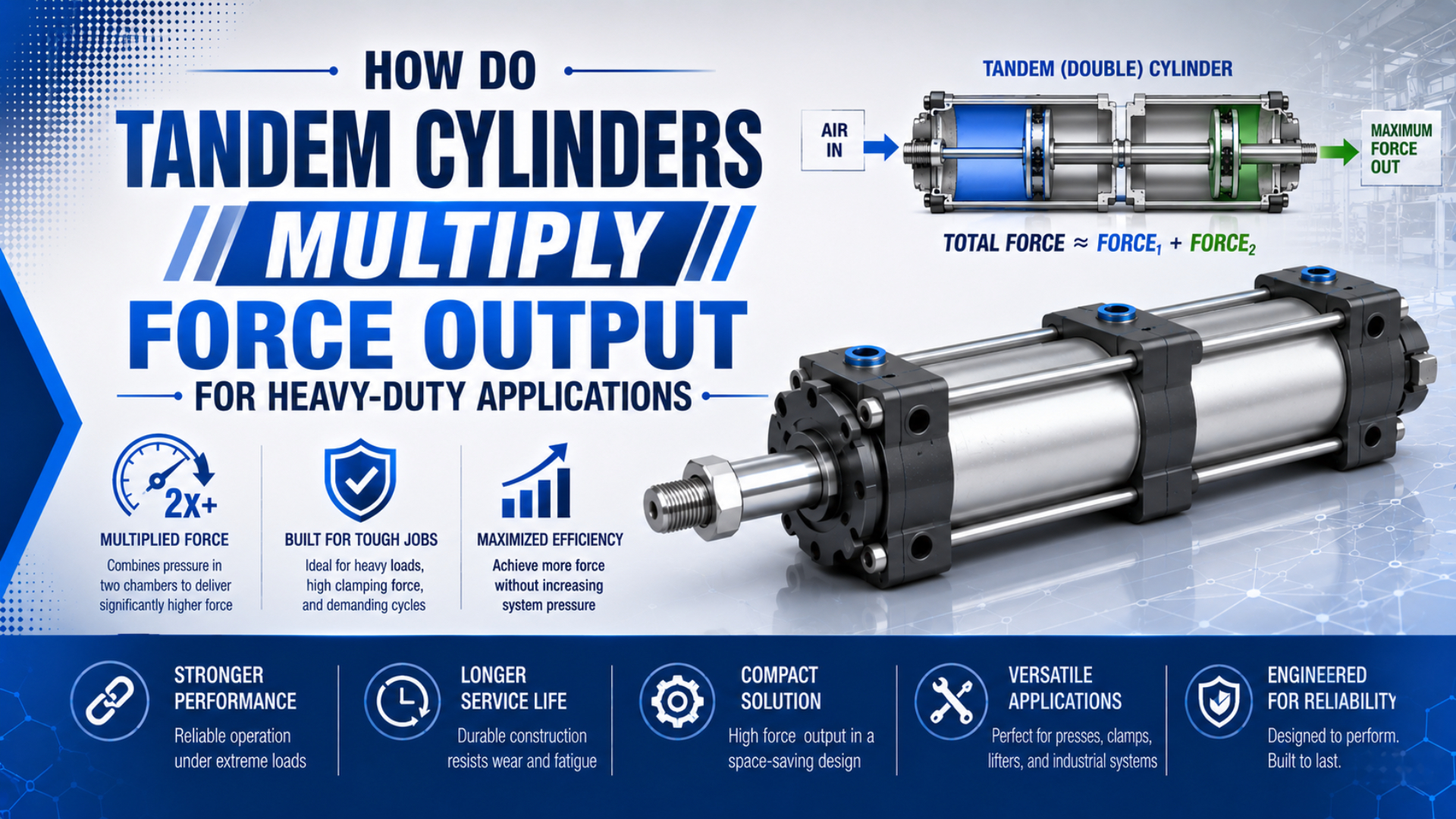
Tandem cylinders increase force by placing two pneumatic power stages in line and transferring both piston forces through a common piston rod. When both working chambers receive pressure, their effective areas add. The actuator can therefore provide nearly twice the force of one same-bore cylinder without requiring a larger bore.
That advantage has a boundary. A tandem unit is usually narrower than a single cylinder selected for the same force, but it is longer, consumes more compressed air, needs more flow, and sends the combined reaction load into one rod, mount, and machine structure. “Double force” is a first-pass description, not a complete sizing result.
Key Takeaways
- SMC describes a dual tandem as two inline cylinders that double output force when both working ports are pressurized.
- Add the effective areas of the pressurized stages; do not multiply an unverified catalog force.
- A dual 63 mm tandem at 6 bar gives about 3.74 kN by ideal area calculation, while the selected catalog model may differ.
- Check air demand, valve flow, axial length, mounting reaction, rod stability, cushioning, and machine safety before selection.
How Does a Tandem Cylinder Multiply Force?
SMC defines its tandem option as two air cylinders arranged in line and states that output doubles when both corresponding ports are pressurized (SMC Made-to-Order Tandem Cylinder, 2024). The shared rod adds the forces mechanically, so no separate motion-synchronization controller is needed inside the integrated actuator.
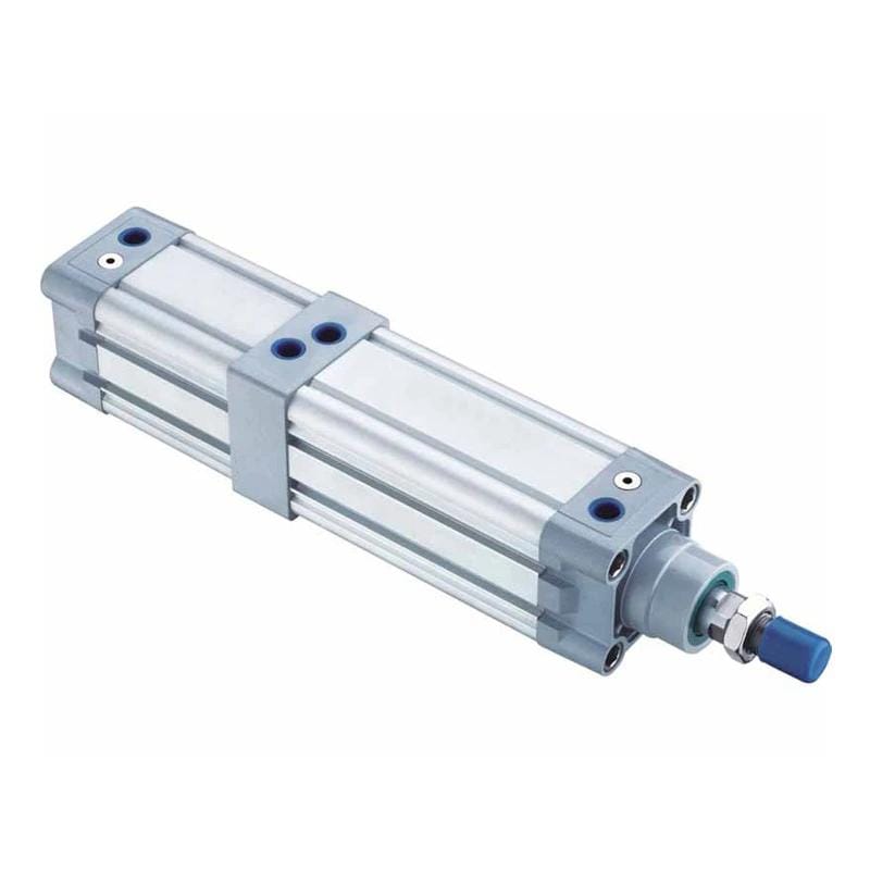
A tandem cylinder is an integrated linear actuator with two cylinders connected in series and a common piston rod. For extension, pressure is supplied to the advance chamber of each stage. For retraction, pressure is supplied to the return chamber of each stage. The output rod carries the sum of the stage forces to one load.
This is different from three nearby concepts:
| Arrangement | What is connected | Primary purpose | Main control issue |
|---|---|---|---|
| Tandem cylinder | two power stages on a common rod | more force at the same nominal bore | feed and exhaust all working chambers correctly |
| High-force stacked cylinder | two to four compact pistons in series | scalable force in a limited radial envelope | model-specific force, length, sensing, and cushioning |
| Multi-position cylinder | separate strokes or cylinder sections | three or more discrete positions | stop sequence and position logic |
| Separate parallel cylinders | independent rods acting on one mechanism | distributed force or load support | synchronization, load sharing, guidance, and binding |
Festo describes tandem cylinders as two identical profile-barrel cylinders connected in series to double thrust in both directions. Its separate high-force family can use as many as four pistons in series (Festo Tandem and High-Force Cylinders, 2026). Do not assume every tandem product supports three or four stages; check the actual series.
[UNIQUE INSIGHT] Tandem force is not “pneumatic synchronization.” The pistons are mechanically tied to one rod, so their positions cannot drift apart like two independent cylinders. The engineering problem moves elsewhere: each chamber still needs adequate pressure and exhaust flow at the same point in the stroke.
What Is the Correct Tandem-Cylinder Force Equation?
Parker defines theoretical cylinder force as pressure multiplied by effective piston area (Parker Pneumatic Application Engineering Data, 2025). A tandem calculation applies that rule to every stage and sums the results. Use the pressure differential at the cylinder ports, not only the regulator or compressor-room gauge.
Theoretical tandem force is the sum of the pressure-area force generated by every active stage before application load allowance. It is a calculation ceiling, not a guarantee of force at the machine tooling.
For an extending tandem cylinder, a complete pressure balance is:
Here, is theoretical extension force in newtons, is the number of powered stages, is the pressure in each advancing chamber, is its effective piston area, is opposing rod-side pressure, and is the corresponding annular area. Use consistent pressure and area units.
If all stages have equal bore, receive the same pressure, and exhaust with negligible back pressure, the first-pass equation becomes:
In this simplified expression, is working gauge pressure at the actuator, is bore diameter, and is the count of equal effective piston areas. With pressure in megapascals and area in square millimeters, the result is in newtons because 1 MPa equals 1 N/mm².
For example, two equal stages use , but only when both stages expose the assumed area and receive the assumed pressure. A model with different effective areas must be calculated stage by stage.
For retraction, rod area reduces the pressure-receiving area:
The exact rod-side geometry can differ by construction. Use the manufacturer’s advance and return force ratings when available. The rod-area calculation guide explains why retraction area is smaller, while the pressure-and-area force worksheet covers the base unit conversions.
Theoretical force is not allowable load. Load ratio is the required application load divided by theoretical cylinder force. A useful selection expression is:
Here, is load ratio, is the worst credible required force, and is theoretical force in the applicable direction. SMC’s selection guide lists 0.7 or below for static work and 0.5 or below for specified dynamic load cases, with lower ratios for high speed (SMC Air Cylinder Model Selection, 2026). Apply the selected product’s method rather than treating those values as universal constants.
Worked Example: A 63 mm Dual Tandem at 6 bar
Parker’s metric force table gives a 63 mm piston area of 31.2 cm² and about 1,870 N theoretical extension force at 6 bar (Parker P1D Cylinder Catalog, 2025). Two ideal full-bore stages therefore produce about 3,740 N before back pressure and application allowances.
Start with the area of one 63 mm piston:
At 6 bar, pressure is 0.6 N/mm². The ideal force of one full-bore stage is:
For two equal full-bore stages:
This result is an ideal geometry check, not a purchase specification. Festo’s current DNCT-63 tandem data lists 3,552 N theoretical advance force and 3,364 N theoretical return force at 6 bar (Festo DNCT-63 Technical Data, 2026). The catalog values reflect the selected product’s actual force areas and construction.
The same area rule exposes an important comparison. Two 100 mm pistons have half the total area of one 200 mm piston, not the same area. At equal pressure, four 100 mm full-bore stages would be required to match the theoretical area of one 200 mm bore. Envelope, cost, flow, stroke, and product availability still decide whether that arrangement makes sense.
[PERSONAL EXPERIENCE] In our experience, we found that the most common tandem-cylinder worksheet error is not the circle formula. It is multiplying a force number without recording whether it is extension or retraction, which pressure produced it, and whether it is theoretical, effective, or catalog-rated force. From our work, naming those conditions is the fastest correction.
Why Is Catalog Force Usually Less Than a Simple Multiple?
Parker describes its P1D tandem as providing “almost twice” the force of one cylinder, while SMC describes its made-to-order dual arrangement as doubling output when the correct port pairs are pressurized (Parker P1D, 2024; SMC, 2024). Both statements require the exact product circuit and rating context.
Several effects separate an area calculation from force available at the load:
- Actual effective areas: a common rod, internal interfaces, or product construction can change the pressurized area in one or both directions.
- Dynamic pressure loss: valve, manifold, tubing, fittings, and shared supply passages can reduce chamber pressure while the actuator moves.
- Exhaust back pressure: restricted exhaust, silencers, meter-out controls, and undersized valves oppose the driving chambers.
- Seal and bearing resistance: more stages add sealing interfaces and internal friction.
- Acceleration and gravity: the cylinder must accelerate moving mass and may have to support a vertical load before useful process force remains.
- External guide friction or misalignment: the output rod can show adequate calculated force while the machine consumes it in a poor load path.
Measure pressure close to the actuator ports during the difficult part of the stroke. A regulator set to 6 bar does not prove every advancing chamber remains at 6 bar while all tandem volumes fill. If the actuator stalls or slows only under motion, compare chamber pressure, exhaust pressure, and valve flow before changing bore.
[UNIQUE INSIGHT] Adding pistons increases static area immediately, but useful force appears only after every active chamber reaches pressure. A tandem cylinder can pass a static force calculation and still miss cycle time because its shared valve and tubing cannot fill the added volume fast enough.
What Flow and Air-Consumption Penalties Come With More Force?
Parker states that cylinder air requirement is determined from cylinder volume and strokes per minute (Parker Application Engineering Data, 2025). For equal bores and strokes, adding a second powered stage approximately doubles swept chamber volume, so the valve and supply must fill and exhaust roughly twice the volume per cycle.
The geometric volume of one full-bore chamber is:
Here, is swept volume, is effective chamber area, is bore, and is stroke. For a tandem unit, sum the actual advance and return chamber volumes from the product drawing. Then convert displaced volume to free-air consumption using absolute pressure and the site’s reference conditions.
More piston area creates four practical consequences:
- Higher air use per cycle. A dual same-bore tandem does not create extra force for free. Its second power stage consumes additional compressed air on extension and retraction.
- Higher required valve flow. Keeping the same stroke time requires enough flow to fill the combined chamber volume without excessive dynamic pressure drop.
- More exhaust capacity. Every opposing chamber must vent. A small silencer or meter-out valve can create back pressure that subtracts from output force.
- Potentially slower motion. Reusing a valve and tube selected for one cylinder can make the tandem unit slower even though its static force is higher.
What happens if the added piston area is connected to the original valve and tubing? Static force may eventually reach the target, but filling time grows and pressure can collapse during motion. Treat force and cycle time as two separate acceptance tests.
Use the Air Consumption Calculator to estimate demand from bore, stroke, pressure, and cycle rate. For a cycle-time target, the Cylinder Flow Requirement Calculator provides a separate flow check. These are secondary checks; the force calculator remains the primary tool for this article.
Do not size the valve from port thread alone. Compare required flow with the valve’s rated flow method, allowable pressure drop, tubing inside diameter, fitting restrictions, and simultaneous demand from every powered chamber. If the tandem cylinder must build clamping force before a process starts, also define the permitted pressure-rise time.
Mechanical and Safety Checks Before Selection
ISO 4414:2010 addresses significant hazards in pneumatic systems and applies to system design, construction, modification, installation, adjustment, maintenance, and intended operation (ISO 4414:2010, confirmed 2021). A tandem actuator concentrates the combined output in one load path, so the rod connection, mount, frame, guarding, and control circuit must all withstand that result.
Check these items before approving the actuator:
| Check | Why tandem force changes it | Evidence required |
|---|---|---|
| Mounting reaction | the mount transfers the combined stage force | manufacturer mounting limits and frame calculation |
| Rod compression | higher push force can reduce buckling margin | rod diameter, unsupported length, end conditions, stroke, load |
| Side load and alignment | tandem force does not create guidance | guide capacity, alignment tolerance, moment and side-load data |
| End-of-stroke energy | added piston mass and machine speed affect stopping energy | moving mass, speed, cushion rating, external stop or shock absorber data |
| Holding a vertical load | compressed air is not a positive mechanical restraint | risk assessment, load-holding device, safe exhaust strategy |
| Stored energy | several chambers can remain pressurized | isolation, pressure release, verification, and lockout procedure |
| Machine structure | a smaller bore does not reduce output reaction | load-path drawing, fastener checks, deflection and fatigue review |
Parker notes that mounting style, stroke, rod diameter, and the way the load connects to the rod all affect cylinder application (Parker Engineering Data, 2025). The full tandem force should act on the cylinder centerline. Use external guides for side loads rather than asking the piston rod and seals to guide the machine.
For a compression stroke, check the rod with the Pneumatic Cylinder Rod Buckling Calculator. That calculation needs unsupported rod length and end conditions, not only bore and force. The separate side-loading guide explains why a larger force reserve cannot correct poor alignment.
Review cushioning independently. The tandem cylinder’s higher force rating does not mean its internal cushion can stop any attached mass at any speed. Compare the product’s permitted impact energy with the moving mass and velocity, then add an external stop or shock absorber when the manufacturer requires it.
When Should You Choose a Tandem Cylinder?
Festo offers DNCT tandem cylinders from 32 mm to 125 mm bore and describes them as two ISO-profile cylinders connected in series for double thrust in both directions (Festo Tandem Cylinder Range, 2026). The arrangement fits best when radial space is restricted but added axial length, flow, and air use are acceptable.
Which dimension is actually constrained, diameter or length? Answer that before choosing tandem construction. A machine with spare axial room may benefit from the narrower bore envelope, while a shallow fixture may be better served by a larger single bore or another force technology.
Choose a tandem cylinder when:
- the required force exceeds a practical single-bore option;
- machine width or cylinder diameter is the dominant envelope constraint;
- a catalog tandem product meets stroke, pressure, temperature, cushioning, and mounting requirements;
- the plant air system and valve can supply the combined chamber volume within the cycle time;
- the rod, guides, mounting hardware, and machine frame can carry the combined load;
- clean pneumatic operation is required and the necessary force remains within a realistic pneumatic range.
Compare alternatives before committing. For instance, a larger single-bore cylinder may simplify plumbing when radial space is available, while tandem construction can protect a narrow machine envelope when extra axial length is acceptable.
| Alternative | Prefer it when | Tradeoff to review |
|---|---|---|
| Larger single-bore cylinder | radial space is available and simpler plumbing is valuable | larger diameter, mount size, and moving mass |
| Tandem cylinder | radial envelope is tight but axial length is available | added air use, ports, length, and flow demand |
| High-force stacked cylinder | a supported product offers more than two stages | model-specific stroke, force, sensing, and length |
| Mechanical toggle or linkage | peak force is needed near one position | changing force ratio, geometry, pinch points, and control |
| Hydraulic cylinder | very high force, stiffness, or controlled load holding dominates | hydraulic power unit, leakage control, heat, and maintenance |
| Servo-electric actuator | programmable position, force profile, and repeatability dominate | peak-force sizing, duty cycle, thermal limit, and cost |
A tandem cylinder is not automatically more compact in total volume. It trades diameter for length. SMC’s made-to-order dimensions show tandem overall length terms that include two stroke lengths, which makes the axial penalty explicit (SMC Tandem Dimensions, 2024).
It is also not automatically cheaper or easier to maintain. Compare the exact actuator, valve, fittings, tubing, mounts, guides, air consumption, spare-parts strategy, and installation access. Supplier lead time and lifecycle cost belong in the project quotation, not in a universal percentage claim.
What Data Belongs in a Tandem-Cylinder RFQ?
Festo’s current DNCT-100 data specifies bore, stroke range, operating pressure, theoretical advance and return force, cushioning, temperature, media, ports, and mounting interfaces (Festo DNCT-100 Data Sheet, 2025). An RFQ should provide the application-side values needed to compare against the same catalog fields.
Include:
- required process force and whether it applies during extension, retraction, or both;
- load ratio or safety method required by the machine design;
- bore, stroke, rod diameter, number of stages, and preferred cylinder standard;
- pressure measured at the actuator during motion and expected exhaust back pressure;
- target extend time, retract time, dwell time, and cycles per minute;
- valve model, rated flow method, tubing inside diameter, tube length, and fitting arrangement;
- available radial envelope, allowable overall length, and port-access restrictions;
- load direction, moving mass, guide arrangement, side load, moment, and rod connection;
- mounting style, frame stiffness, fastener details, and expected reaction load;
- minimum and maximum ambient temperature, air quality, washdown, dust, chemicals, and corrosion exposure;
- position sensing, cushioning, external stops, shock absorbers, and required impact-energy capacity;
- safety functions, vertical-load controls, trapped-pressure release, and applicable machine standards;
- photos, layout drawing, current model number, failure history, and any approved alternative technologies.
Ask suppliers to identify whether quoted force is theoretical, effective, or measured, and at what pressure it applies. Advance and return force should be listed separately. If a supplier proposes “two times force,” request the exact chamber areas or the manufacturer’s force table so the number can be reproduced.
For application review, send the load case, pressure, stroke, cycle time, envelope drawing, guide arrangement, and safety requirements through the technical contact page.
Tandem Cylinder FAQs
SMC documents a dual inline tandem that doubles output when both working port pairs receive pressure, while Parker describes its tandem product as providing almost twice the force (SMC, 2024; Parker, 2024). These FAQs explain where the ideal multiplier stops and product-specific selection begins.
Does a dual tandem cylinder always produce exactly twice the force?
No. Two equal ideal piston areas at equal pressure produce twice the theoretical area-force result. Actual catalog force can differ because effective areas, rod geometry, seals, internal construction, dynamic pressure drop, and exhaust back pressure vary. Use the exact model’s advance and return force ratings for final selection.
Is a tandem cylinder shorter than one large-bore cylinder?
Usually not. Tandem construction trades radial size for axial length by placing power stages in line. It can fit a narrow machine envelope while becoming longer than a single cylinder. Compare the complete dimensional drawing, including stroke-dependent length, mounts, rod accessories, fittings, and service clearance.
Does doubling tandem force also double air consumption?
For two equal bores and strokes, the swept chamber volume is approximately doubled, so air consumption per cycle also rises substantially. The exact result depends on advance and return volumes, pressure, dead volume, and reference conditions. Valve flow and exhaust capacity must also increase if stroke time is unchanged.
Can two separate cylinders be treated as a tandem cylinder?
Not automatically. An integrated tandem uses a common rod, so its pistons move together mechanically. Two independent cylinders acting on one mechanism can fight each other when flow, friction, alignment, or load distribution differs. That arrangement needs a separate synchronization, guidance, and structural analysis.
Can a tandem pneumatic cylinder replace a hydraulic cylinder?
Sometimes, when the required force, duty cycle, stiffness, speed, holding method, and envelope remain practical for compressed air. It is not a universal replacement. High static force, controlled load holding, low compliance, or severe shock may favor hydraulic, mechanical, or servo-electric solutions after a risk-based comparison.
Where Do the Technical Limits Come From?
The calculation and selection boundaries above use five primary references: SMC’s tandem construction and load-ratio guidance, Parker’s force and air-volume engineering data, Festo’s current tandem product range and catalog forces, and ISO 4414 safety requirements. The worked values are labeled as either calculated geometry or manufacturer data so they are not interchangeable.
- SMC Made-to-Order Tandem Cylinder. Port pairs, double-output description, applicable series, and dimensions. Retrieved 2026-07-19.
- SMC Air Cylinder Model Selection. Load-ratio and operating-pressure selection guidance. Retrieved 2026-07-19.
- Parker Pneumatic Actuator Application Engineering Data. Force equation, piston area, mounting, and air-requirement methods. Retrieved 2026-07-19.
- Parker P1D Pneumatic Cylinder Catalog. Tandem construction and “almost twice” force description. Retrieved 2026-07-19.
- Festo Tandem, High-Force, and Multi-Position Cylinders. Product-family distinctions and tandem range. Retrieved 2026-07-19.
- Festo DNCT-63 Technical Data. Current 63 mm advance and return force values at 6 bar. Retrieved 2026-07-19.
- ISO 4414:2010. General rules and safety requirements for pneumatic systems and components. Retrieved 2026-07-19.
- YouTube: How to Select a Pneumatic Cylinder. Supplemental force and bore-selection walkthrough. Retrieved 2026-07-19.