

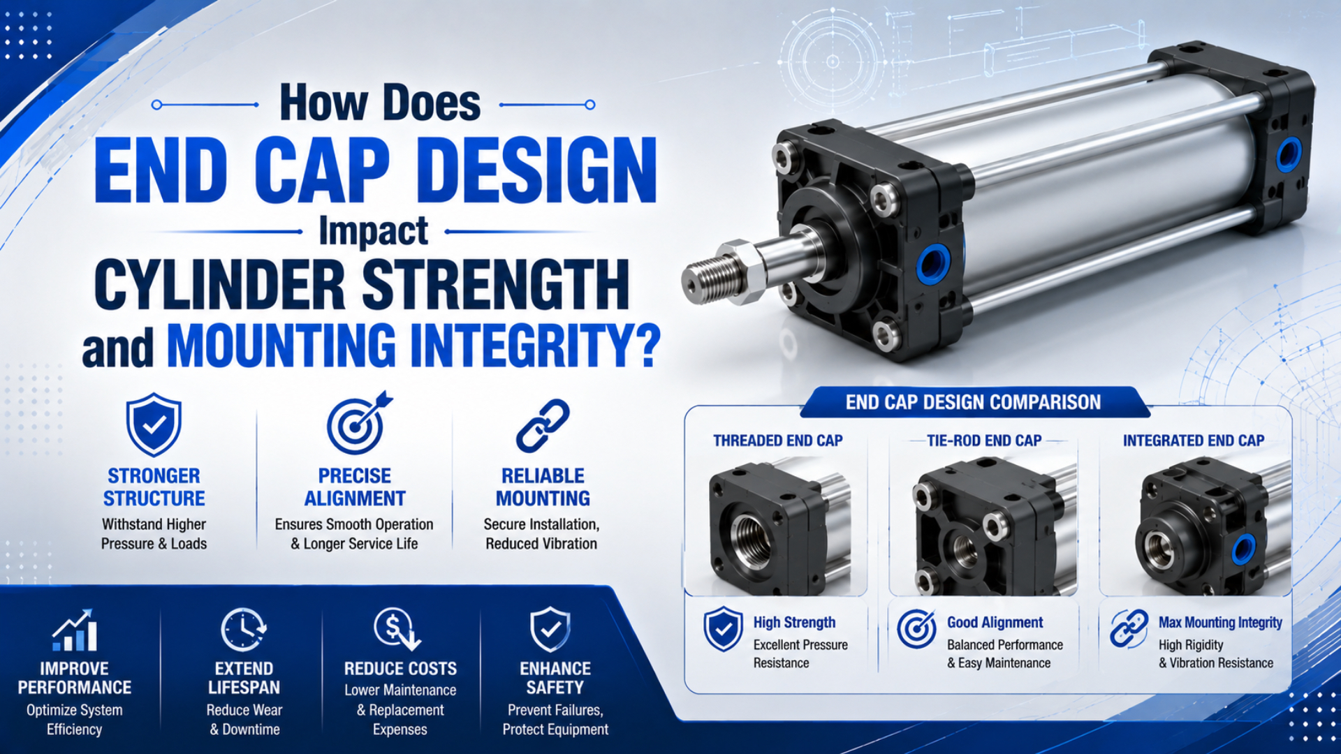
Pneumatic cylinder end cap design affects strength in four ways: it closes the pressure vessel, locates the barrel and seals, supports ports and cushioning hardware, and provides selected mounting interfaces. Yet the cover never works alone. Retention depends on tie rods or profile screws. Seals, fasteners, the machine frame, the rod connection, and external guidance complete the load path.
That boundary prevents two common errors. Standardized bolt patterns do not prove equal structural capacity. Nor does a thicker-looking cover prove that the installed cylinder can tolerate misalignment or side load. Engineers need configured-cylinder data, the machine’s load geometry, and physical inspection evidence. Direct evidence settles the question.
Key Takeaways
- ISO 15552 covers detachable-mount cylinders from 32-320 mm at up to 10 bar, but it standardizes dimensions rather than end-cap strength.
- Pressure force, barrel retention, and machine mounting loads require separate checks.
- Approve replacements from configured drawings, manufacturer limits, installation measurements, and first-article testing.
Publisher information and a route for technical corrections are available through About Us and Contact.
What Loads Must a Pneumatic Cylinder End Cap Carry?
ISO 15552 covers detachable-mount cylinders from 32-320 mm bore at a maximum rated pressure of 1,000 kPa, or 10 bar, but its published scope is dimensional interchangeability (ISO 15552:2018, confirmed 2025). End-cap load capacity must therefore come from the configured product design and application review.
An end cap closes one chamber end. Internal pressure acts over the bore area, creating an axial separating force that the complete cylinder structure must retain. In a tie-rod design, both covers work with the rods, their nuts or threads, the barrel, and static seals. Profile cylinders route the same reaction through their barrel features and end-cover fasteners.
Use the separate tie-rod preload and torque guide when rebuilding a clamped assembly; this article does not provide tightening values.
Ideal pressure force follows this relationship:
In this equation, is pressure force in newtons and is gauge pressure in pascals. Unit consistency prevents silent errors. The pressurized area is measured in square metres; bore diameter is in metres. Festo also calculates piston force from operating pressure and area before deducting friction to estimate usable output (Festo General Operating Conditions, 2026).
For example, a 100 mm bore at 6 bar produces about 4.71 kN of ideal pressure force. That value describes one axial pressure reaction. It does not rate the end cover, mounting ears, flange, foot bracket, pivot pin, fasteners, cushion components, or surrounding machine structure.
Because bore area increases with diameter squared, pressure-induced separating force rises much faster than bore diameter. The result is nonlinear. Moving from 32 mm to 100 mm at the same pressure multiplies ideal pressure force by about 9.77. Universal wall-thickness or thread-count tables are therefore unsafe: geometry, material, connection architecture, local stress, proof testing, and manufacturing control all matter.
Pressure is only the first load family. End-mounted flanges also transfer working reaction into the frame. Foot and side mounts can create eccentric moments. Clevises and trunnions carry pin reactions while allowing angular movement. Other inputs include hose force, pipe strain, cushion impact, hard-stop load, misalignment, and unsupported payload. None appears in the pressure-force equation. A complete free-body diagram must show these external reactions and where the machine structure resists them. Before selecting hardware, sketch each reaction at the worst stroke position and include the offset from the supported axis.
Review the linear-actuator side-loading guide to check transverse force and offset separately from cylinder thrust.
How Does the End Cap Join the Barrel and Retain Pressure?
Parker’s P1F ISO 15552 range uses aluminum end covers. Bore sizes span 32-125 mm. Available strokes run from 5-2,000 mm, and operating pressure is 1-10 bar (Parker P1F Catalog, 2025). Those product facts do not create a universal recipe for cover material, wall thickness, or fastener engagement.
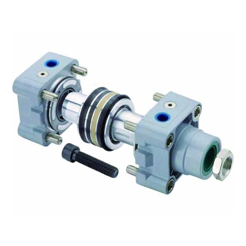
Pressure boundary is the complete set of parts and interfaces that contains compressed air. Trace the first bubble. Around an end cover the boundary commonly includes the barrel-to-cap sealing surface and static seal. Locating geometry, retention fasteners, port threads, cushion passages, and adjustment hardware complete it. Leakage at one interface can occur even when the casting or machined cover remains intact.
Common construction families distribute retention differently:
For packaging, sensor-slot, cleanliness, retrofit, and service-route tradeoffs, consult the profile-versus-tie-rod cylinder comparison; the table below stays with end-cover retention and inspection evidence.
| Cylinder construction | How the end covers are retained | What must be verified |
|---|---|---|
| External tie rods | Rods clamp both covers against the barrel and static seals | Tie-rod condition, specified tightening method, sealing faces, barrel seating, cover alignment |
| Profile barrel with end-cover screws | Fasteners connect each cover to reinforced features in the profile | Correct screw grade and length, thread condition, torque sequence, profile damage, cover location |
| Round-body or compact construction | Threads, through bolts, crimping, rolling, or proprietary retention may be used | Manufacturer serviceability, pressure rating, approved repair method, replacement compatibility |
| Integrated manifold or valve cover | End cover also carries pneumatic passages or control hardware | Port sealing, valve compatibility, local stresses, access, contamination control |
Do not infer serviceability from appearance. Removable-looking covers may still require factory fixtures and a controlled tightening sequence. Some demand new static seals; others are not field-serviceable. Conversely, a repairable tie-rod design still needs its exact parts list and assembly instructions. Use the repair-versus-replace decision framework when the cover, barrel seat, threads, or locating features are damaged. Ports and cushion adjusters deserve separate attention because drilled passages interrupt the local section and introduce new sealing interfaces. Suppliers control their position, surrounding material, thread form, surface finish, seal type, and proof test. Adding a larger port or re-machining a damaged cushion bore without an approved design review changes the pressure boundary.
Appearance misleads.
An external leak near the end cover does not identify the failed part. Clean the area, locate the first bubble path with an approved leak-detection method, and distinguish among the tube-to-cover static seal, port fitting, cushion screw, sensor or valve interface, and damaged cover. Replacing the end cap before locating the path can erase useful evidence.
Mounting Style Determines the Load Path
ISO 21287 covers compact cylinders from 20-100 mm bore. Within that scope, cylinders from 32-100 mm may use ISO 15552 end-cover mountings (ISO 21287:2004, confirmed 2023). That compatibility does not establish an equal mount rating. Materials and fasteners may differ, as may allowable moments. Compatibility remains conditional.
Mounting load path is the route by which cylinder reaction travels through the attachment and fasteners into the machine frame. Rear flanges can keep force near the pressure centerline. Feet sit below that axis, while rear clevis pins introduce bearing reactions. Consequently, identical axial working force can produce very different local stresses in the cover and bracket.
| Mounting family | Intended motion relationship | End-cap or frame concern | Installation check |
|---|---|---|---|
| Front or rear flange | Fixed, straight-line motion | Flange bending, bolt tension/shear, flatness, pilot location | Keep the force path close to the cylinder axis and verify full-face seating |
| Foot or side mount | Fixed body with an offset mounting plane | Eccentric moment, slip, frame bending, thermal constraint | Use the manufacturer’s locating method and verify the support does not twist under load |
| Rear clevis or spherical pivot | Cylinder swings through an arc | Pin bearing, lug bending, pin-axis alignment, angular clearance | Keep body and rod-end pivot axes parallel and free through the complete motion |
| Trunnion | Cylinder pivots around side pins | Pin bending, bearing-block alignment, shoulder clearance | Support both trunnions coaxially and close to their shoulders |
| Direct end-face threads | Compact fixed mounting | Thread engagement, surface flatness, screw length, local distortion | Use only the documented holes, fastener grade, torque, and mounting face |
Parker notes that some cylinder mountings have restrictions such as minimum stroke or pressure derating and instructs users to review the selected catalog (Parker Cylinder Safety Guide, accessed 2026). Treat the bolt pattern as an interface, not a load rating.
Machine designers own the mating structure. Check bracket thickness and weld location first. Then verify bolt preload, specified shear keys or dowels, pivot-pin bearing length, and tightening access. Even a rigid bracket is wrong when it locks a pivoting mechanism or places the cylinder centerline away from the guided load.
For multi-configuration machines, document the attachment location for every accessory. The front cap, rear cap, profile, and separate bracket are not interchangeable datums. Compatibility is conditional. Festo’s DSBC matrix identifies foot mountings for bearing or end caps and records option restrictions (Festo DSBC Catalog, 2023). Use the multi-mount actuator interface method when one body supports several released variants.
What if the bracket holes line up but tightening them pulls the rod sideways? Stop. The installation is storing misalignment. The mounting and alignment acceptance guide covers datum selection and loaded checks without treating the end cap as an alignment corrector.
Which End Cap Materials and Details Matter Most?
Parker’s P1F catalog specifies aluminum end covers with zinc-plated-steel end-cover screws for its standard 32-125 mm ISO 15552 range, while corrosion-resistant options change material or surface treatment (Parker P1F Catalog, 2025). Material choice is therefore configuration-specific, not a generic aluminum-versus-steel contest.
End cap design is a controlled combination of material, geometry, interfaces, manufacturing process, and acceptance evidence. Drawings must identify the alloy and condition. They also need the coating and applicable specification. “Aluminum” omits yield strength, heat treatment, porosity control, and corrosion performance; “steel” omits grade, hardness, plating, and embrittlement controls.
Geometry matters as much as handbook material values; review the complete feature set:
- transition radii around mounting lugs, flanges, ports, and cushion bosses, including the tool access needed to reproduce those radii consistently after a design revision;
- abrupt section changes between the pressure cavity and external mounting face, especially where a local boss meets a thinner wall;
- sealing-groove dimensions, lead-ins, edge condition, and the specified surface finish;
- thread form and effective engagement, plus edge distance, inserts, fastener seating, and access for controlled tightening without side-loading the screw head;
- locating pilots and bearing surfaces that keep bolts from becoming unintended dowels;
- drainage in washdown service;
- coating coverage and galvanic material pairs, including damage that exposes the base metal;
- machining datums that jointly control barrel location, bearing alignment, port position, and mounting geometry after assembly.
No universal “best” wall thickness, thread count, or safety factor exists. Approval begins with pressure and bore. Architecture and material allowables come next. Context decides. Further constraints include local stress and fatigue duty. Manufacturing process, proof requirements, and failure consequence also matter. Finite-element analysis can support the review only after loads and contacts are defined. Material data, mesh quality, and acceptance criteria must also be explicit. A colorful stress plot proves nothing by itself. Manufacturing evidence must match the risk; material certificates alone are insufficient. A suitable plan may require casting or forging controls, dimensional inspection, thread gauges, surface-finish checks, coating verification, and pressure or leakage tests. Fastener traceability plus controlled assembly records close the build history.
ISO 10099 provides final examination and acceptance criteria for double-acting single-rod pneumatic cylinders, but the supplier’s configured procedure still defines the release record (ISO 10099:2001, confirmed 2023).
Geometry is not optional.
Harsh environments widen the review. Washdown, chemicals, abrasive dust, and weld spatter can attack different interfaces. Cover material is only one part of the package. Seals and rod surfaces need compatible ratings; so do fasteners, fittings, sensors, lubricants, bellows, and drainage provisions.
How Should Engineers Inspect, Correct, and Specify an End Cap?
Parker requires piston-rod alignment checks in 2 positions, fully extended and fully retracted, because misalignment increases rod-gland or bore wear (Parker Cylinder Safety Guide, accessed 2026). Inspect the installed load path before removal; bench crack checks cannot reveal assembly strain.
Before hands-on work, use the machine’s approved energy-control procedure. Secure every moving or suspended load. Isolate pneumatic energy along with other sources, release trapped pressure, and verify the safe state. ISO 4414 applies safety principles across the design, construction, installation, adjustment, maintenance, and reliable operation of machinery pneumatic systems (ISO 4414:2010, confirmed 2021).
Then preserve the evidence:
- Record the operating condition. Note pressure during motion, stroke position, direction, payload, and speed. Add cycle rate, cushion setting, temperature, and the exact moment when the symptom appears. Preserve the last known good record if one exists.
- Photograph before cleaning. Capture crack direction, witness marks, bracket gaps, and the cylinder’s installed clock position.
- Locate the leak or movement. Separate port leakage from the cushion adjuster, barrel-to-cover joint, rod seal, and internal bypass. Apply the approved detection method before disturbing fittings. Mark any interface that moves under load, including washers or brackets that return after pressure is removed.
- Check alignment through the stroke. Compare retracted, mid-stroke, and extended positions. Repeat under representative load when permitted.
- Inspect every mating interface. Check the cover and barrel seats first. Then examine static-seal grooves, threads, fasteners, pilots, flange faces, pivot pins, and bushings. Measure bracket flatness and frame damage against exact service limits rather than judging them by eye.
- Set repair scope from evidence. Seal kits cannot restore stripped threads, distorted locating geometry, cracked lugs, damaged barrel seats, or uncorrected alignment.
- Commission progressively. Verify assembly and free movement before applying the full duty. Check leakage, alignment, and fastener control at reduced energy when the approved procedure allows it. Finish with cushioning, sensor, and loaded-performance acceptance before releasing production.
| Evidence | Likely branches | Next check |
|---|---|---|
| Crack starts at a lug radius or bolt hole | Eccentric mounting load, poor seating, loose fastener, local defect | Crack origin, bracket flatness, load direction, bolt preload, material record |
| Static-seal leak at one point | Damaged seal, groove defect, cover tilt, barrel-seat damage | Seal condition, groove dimensions, fastener sequence, barrel seating |
| Repeated loose mounting bolts | Joint slip, insufficient preload, vibration, frame deflection | Fastener specification, mating surfaces, locating method, dynamic movement |
| Port thread damage | Pipe strain, wrong thread, overtightening, repeated fitting work | Thread identity, fitting engagement, hose support, cover replacement criteria |
| Binding after mount bolts are tightened | Misalignment or distorted mounting face | Indicator movement before and after tightening, guide datum, shimming method |
| Cushion screw or boss damage | End-of-stroke energy, wrong adjustment, impact, unauthorized repair | Moving mass, speed, cushion capacity, hard-stop location, replacement instructions |
In our experience, the most valuable evidence is often a simple before-and-after tightening check. If rod position, breakaway resistance, or bracket gap changes when the end-cap mount bolts reach torque, the joint is pulling the cylinder into the machine rather than seating without strain. Correct that geometry before installing another cover or seal kit.
For a replacement or RFQ, provide the complete cylinder code, bore, stroke, operating-pressure range, mount and accessory codes, rod-end joint, orientation, guide arrangement, payload and center of gravity, speed, cycle rate, cushioning, environment, air quality, port and thread standard, failure photographs, measured damage, and applicable acceptance test. The ISO 15552 interchangeability checklist explains why matching the standardized envelope is only the first approval layer.
Pneumatic Cylinder End Cap FAQs
ISO 15552 covers 32-320 mm detachable-mount cylinders in a 10 bar dimensional series. ISO 4414 addresses pneumatic-system safety across design, installation, and maintenance. Neither document supplies universal end-cap wall thickness, thread count, safety factor, mount strength, or service-life multiplier. Use configured product data and machine-level evidence. Evidence must remain configuration-specific.
Configured evidence decides.
Does ISO 15552 define pneumatic cylinder end cap strength?
No. ISO 15552 defines dimensions needed for interchangeability across 32-320 mm bores at a maximum rated pressure of 10 bar. Its scope covers basic geometry, mountings, and accessories. The document does not publish one allowable end-cap stress, mounting load, wall thickness, or fatigue life for every compliant cylinder. Obtain those limits from the configured product and supplier (ISO, confirmed 2025).
Can I replace only a cracked cylinder end cap?
Only when the manufacturer permits repair and a measured inspection verifies the complete mating structure. The barrel seat, fasteners, threads, locating features, rod alignment, and mount must each remain serviceable. ISO 4414 covers maintenance safety but does not approve a component-specific repair. Fix the cause first. Then complete the specified assembly and acceptance tests (ISO, confirmed 2021).
Is a steel end cap always stronger than an aluminum end cap?
No. Parker uses aluminum end covers on its 32-125 mm P1F ISO 15552 cylinders rated from 1-10 bar. Geometry changes the result. Structural capacity also depends on the retention method. Exact alloy condition, fasteners, local stress, manufacturing control, and test evidence complete the comparison. A generic material name cannot identify the stronger finished design (Parker, 2025).
Which mounting style puts the least stress on an end cap?
No mounting style is universally best. Centerline flanges can route axial force directly. Clevises and trunnions accommodate angular motion, whereas foot mounts introduce an offset reaction for the frame to resist. Parker warns that some configurations require minimum strokes or pressure derating. Select and rate the exact mount for the actual motion and force direction (Parker, accessed 2026).
What data should an end cap replacement RFQ include?
Provide the full cylinder code and identify the front or rear cap. Record bore, stroke, pressure range, mount, accessories, ports, cushioning, rod connection, load geometry, speed, cycle rate, and environment. Include photographs plus measured damage. ISO 15552’s 32-320 mm scope identifies dimensional interfaces; the configured drawing and acceptance test establish suitability (ISO, confirmed 2025).
Sources and technical references
- ISO 15552:2018, detachable-mount cylinder dimensional scope; confirmed 2025, retrieved 2026-07-19.
- ISO 21287:2004, compact-cylinder and end-cover mounting scope; confirmed 2023, retrieved 2026-07-19.
- ISO 4414:2010, pneumatic-system safety requirements; confirmed 2021, retrieved 2026-07-19.
- ISO 10099:2001, final examination and acceptance criteria for double-acting single-rod cylinders; confirmed 2023, retrieved 2026-07-19.
- Parker P1F Pneumatic Cylinder Catalog, configured construction, materials, sizes, and operating pressure; 2025, retrieved 2026-07-19.
- Parker Cylinder Safety Guide, mounting limitations and alignment checks; retrieved 2026-07-19.
- Festo DSBC Catalog, end-cap mounting accessories and combination restrictions; 2023, retrieved 2026-07-19.
- Festo General Operating Conditions, pressure, area, and piston-force relationship; 2026, retrieved 2026-07-19.