

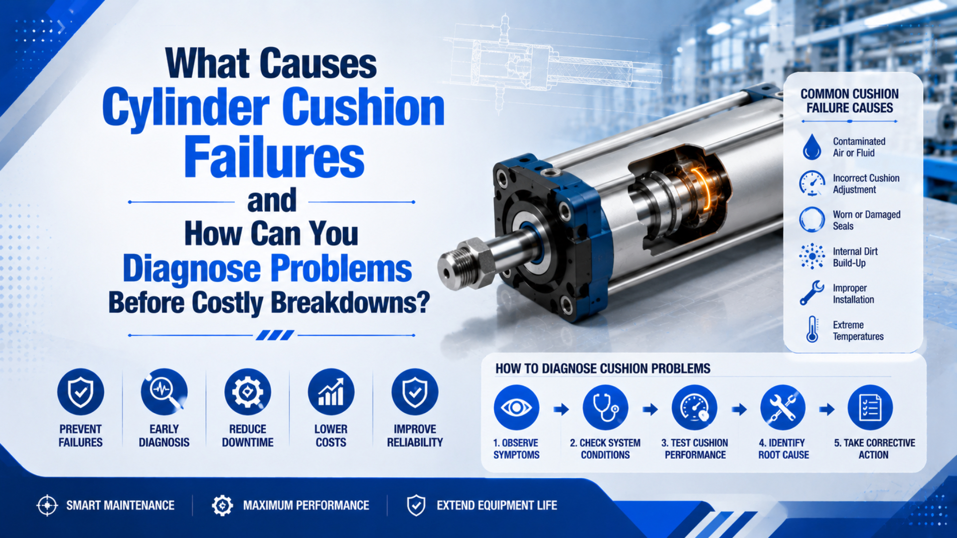
Cylinder cushion failures usually trace to one of six causes: the needle setting is wrong, the moving energy exceeds the cushion capacity, exhaust flow is restricted elsewhere, the cushion seal or check path leaks, contamination has changed a small internal passage, or the cylinder is carrying a mechanical load it was not designed to stop. The fastest diagnosis comes from recording the symptom at each end, measuring the loaded stroke, and changing one variable at a time.
Do not start by turning the cushion screw. A hard stop can be a speed or load problem, while a slow final crawl can come from an over-closed needle, a blocked muffler, or trapped back pressure. Adjusting before recording the original condition removes useful evidence.
Key Takeaways
- Separate a hard impact, bounce, slow final crawl, and one-end-only problem before opening the circuit.
- Compare empty and loaded cycles, extension and retraction, and normal and reduced speed.
- Check moving energy against the exact cylinder catalog. Bore size alone does not prove cushion capacity.
- Treat pressure, stroke time, sound, and vibration as a combined pattern, not four independent diagnoses.
- Isolate pneumatic and mechanical stored energy before inspection or disassembly.
Cylinder Cushion Failures in One Sentence
Cylinder cushion failure is the repeated inability of an end-of-stroke damping system to stop the real moving load within the cylinder manufacturer’s speed, energy, pressure, mounting, and adjustment limits. It is not a diagnosis by itself.
Festo explains that adjustable pneumatic cushioning traps a volume of air in the end chamber and meters its discharge through an adjustment path. The useful setting depends on moving mass, entry speed, working pressure, deceleration, and cylinder resistance (Festo, cylinder cushioning methods, 2022).
That definition matters because the same visible impact can have different causes. A needle left too open cannot build enough back pressure. A correctly adjusted cushion can also hit hard when a heavier tool, faster command, or higher drive pressure raises the energy beyond the model’s rating.
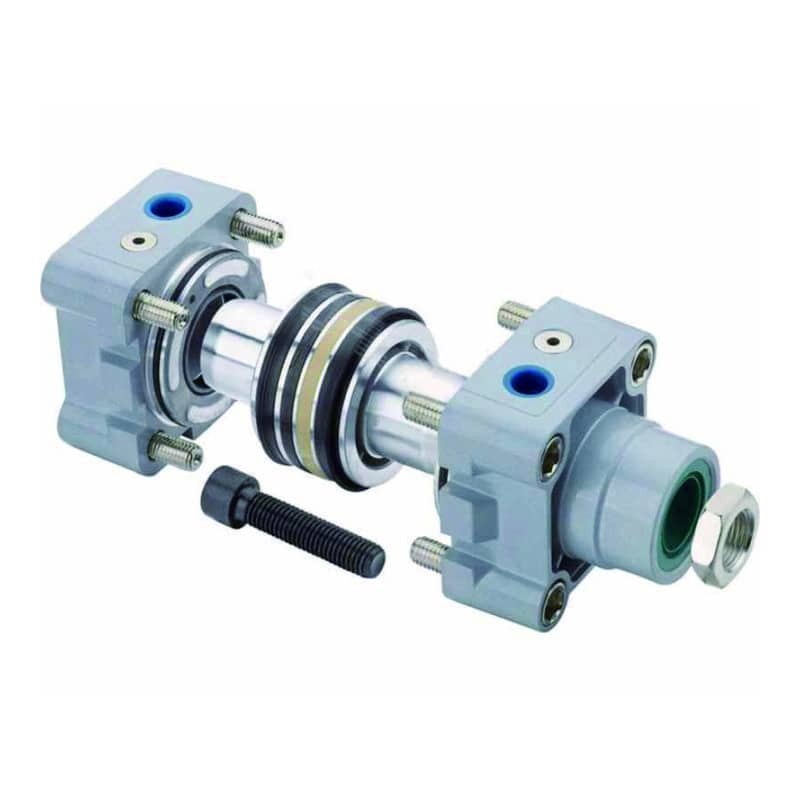
The broader pneumatic cylinder cushioning guide explains how the sleeve, chamber, needle, and check path work. This article stays with failure isolation after the machine already shows a bad stop.
Safety Boundary Before Testing
A cushion diagnosis may require powered observation, but inspection, cleaning, and disassembly require the machine’s approved hazardous-energy procedure. OSHA 29 CFR 1910.147 includes pneumatic energy and requires hazardous stored or residual energy to be relieved, disconnected, restrained, or otherwise made safe before covered servicing work (OSHA 1910.147). ISO 4414 covers safety principles for pneumatic systems and components used on machinery (ISO 4414:2010).
Use approved test ports for any powered pressure measurement. Do not loosen a fitting to see whether air is present, reach through a guard to touch a moving cylinder, or rely on a PLC stop button as the energy-isolating device.
Before changing anything, record:
- Cylinder manufacturer, series, bore, stroke, cushion type, and mounting.
- Load and tooling condition, including whether the axis is horizontal, vertical, or inclined.
- Extension and retraction time under the actual load.
- Supply pressure at rest and at the valve inlet during motion.
- The symptom at the head end and rod end separately.
- Cushion screw position, speed-controller setting, and recent maintenance changes.
Our team found that this short baseline turns a subjective complaint such as “the cylinder bangs” into a test that another technician can repeat. It also prevents a replacement request from losing the load, pressure, and timing conditions that made the fault appear.
Symptom-to-Cause Diagnostic Matrix
The shape of the final movement is more useful than the word “failure.” Listen and watch from a safe position, then match the symptom to the first measurement rather than to a replacement part.
| Observed symptom | Strong first suspects | First useful check | Avoid this shortcut |
|---|---|---|---|
| Sharp impact at both ends | Excess speed, excessive moving mass, cushion too open | Loaded stroke time and cushion-entry speed | Closing both needles fully |
| Sharp impact at one end only | Unequal load, one needle setting, cushion-seal bypass, damaged end components | Compare both directions at reduced speed | Replacing the directional valve immediately |
| Long slow crawl near stroke end | Cushion too restrictive, blocked bleed path, exhaust restriction | Final-zone time, needle position, muffler and exhaust path | Increasing supply pressure |
| Bounce or reversal before the sensor | Excess trapped back pressure, over-closed needle, unstable load | End-zone motion and sensor sequence | Moving the sensor to hide the bounce |
| Stop quality changes with payload | Energy or mounting limit, variable friction | Empty versus full-load timing and energy | Using the empty-cycle setting as acceptance |
| Stop worsens after maintenance | Setting lost, wrong seal or grease, contamination, swapped tubing | Work-order changes and part numbers | Assuming the new component is defective |
| Cylinder body or bracket shakes | Residual impact, loose mounting, side load, poor support | Mounting torque, alignment, guide condition | Treating vibration as only a cushion problem |
The general pneumatic-cylinder troubleshooting guide helps when the symptom includes weak force, sticking, leakage, or no movement outside the end zone.
A Six-Step Isolation Test
A reliable field test moves from the easiest reversible checks to internal inspection. Stop when the evidence identifies an external cause. Opening the cylinder should be the last branch, not the first.
1. Reproduce the fault under controlled conditions
Use the normal load, approved guarding, and a consistent command sequence. Record several cycles because a one-time stop can be affected by load position, supply recovery, or a sticky guide.
If the machine cannot be observed safely at production speed, use the site’s commissioning or diagnostic procedure. Slow motion may help locate a mechanical fault, but it does not prove that the cushion can absorb production-speed energy.
2. Separate one end from both ends
In our experience, one bad end is the most useful early split. It points toward that end’s needle, cushion seal, check path, sleeve, or end cover. Both ends changing together points first toward speed, payload, pressure, valve flow, exhaust restriction, or a common maintenance change.
Do not assume both cushion screws should have the same setting. Extension and retraction move different effective areas, and gravity or tooling can load the directions differently.
3. Compare full load, light load, and reduced speed
If reducing approach speed removes the impact, the cylinder may be outside its energy envelope even when the cushion hardware is intact. If the fault remains nearly unchanged at low speed and only one end is affected, an internal leak, damaged adjustment path, or mechanical stop becomes more plausible.
The high-speed air-cushion guide covers why entry speed, not average cycle speed alone, controls the stop.
4. Check the external exhaust path
Inspect the meter-out flow control, valve exhaust, muffler, tube ID, fittings, and any quick-exhaust valve. A restriction can create back pressure through the whole stroke or make the final zone excessively slow. The back-pressure guide explains how exhaust-side pressure changes cylinder force and timing.
Compare the symptom with and without a suspected muffler only when the machine procedure permits the test and the exhaust remains safely controlled. Do not leave a required silencer or contamination barrier removed.
5. Make one small adjustment
Mark the original needle position. Change one end in small increments and record the result through several loaded cycles. A consistent response to adjustment shows that the metering path still has authority.
Little or no response can indicate a damaged needle, blocked passage, bypassing cushion seal, missing cushion component, or a load so far beyond capacity that adjustment cannot correct it. It can also mean the piston never enters the designed cushion zone because an external stop ends travel early.
6. Isolate energy and inspect the confirmed branch
After applying the approved energy-control procedure, inspect the accessible adjustment screw, locking feature, rod, mount, end cover, and fasteners. Follow the manufacturer manual before removing an end cap or replacing a cushion seal. SMC limits seal replacement and disassembly for some series to qualified personnel or factory support (SMC CG1 series catalog, pp. 75-76).
Keep removed contamination for identification only when the maintenance process supports clean sampling. Metal fragments, elastomer pieces, water, oil residue, and external dust point to different follow-up checks, but appearance alone does not establish the source.
Adjustment Error or Excess Energy?
Adjustment changes the rate of deceleration; it cannot create unlimited absorption capacity. SMC publishes model-specific allowable kinetic-energy values and states that a larger cylinder or an external stopper may be required when the applicable value is exceeded (SMC actuator model-selection data, p. 15).
Use kinetic energy as the first screening term:
where is kinetic energy in joules, is the total moving mass in kilograms, and is speed in metres per second at cushion entry. Parker notes that piston speed at the start of cushioning can be approximately 50% higher than average piston speed, so stroke divided by total time can understate the relevant value (Parker Pneumatic Actuator Products, 2025).
Compressed air may continue doing work while the piston moves through the cushion distance. A useful screening estimate is:
where is the effective drive force during cushioning in newtons and is cushion travel in metres. This is not a universal catalog formula. Vertical motion, changing chamber pressure, friction, external springs, and manufacturer-specific correction factors can change the approved method.
For example, 12 kg moving at 0.6 m/s has 2.16 J of kinetic energy. If an estimated 120 N continues through 15 mm of cushion travel, the drive-work term is 1.8 J, giving a 3.96 J screening total before any catalog safety or application factor. The correct decision comes from comparing the exact series, bore, direction, speed, load, and mounting condition with the current manufacturer data.
Reading Pressure, Time, Sound, and Vibration
No single signal proves a cushion failure, but several signals recorded together can separate likely branches. Use synchronized traces when the machine is critical or the stop changes too quickly for visual observation.
| Evidence pattern | Likely interpretation | Confirmation step |
|---|---|---|
| Impact rises as payload or speed rises | Energy margin is shrinking | Calculate entry energy and compare with catalog data |
| Long end-zone time with no metal impact | Excess restriction or over-closed adjustment | Check needle, exhaust path, and final pressure |
| High pressure followed by visible bounce | Trapped air is braking too abruptly | Open within the model’s approved range and retest |
| Weak pressure rise plus a hard one-end impact | Cushion air may be bypassing | Check setting, seal, sleeve engagement, and test-point location |
| Normal end-zone pressure but the frame shakes | Mechanical stop, mount, guide, or side load | Inspect load path and alignment |
| Impact varies with supply recovery | Circuit pressure or flow instability | Log valve-inlet and both cylinder-port pressures |
Pressure transducers should have enough response and range for the event being measured. A slow plant gauge can confirm static supply but miss a short cushion transient.
An accelerometer or sound reading is most useful for trending a known machine at a defined sensor location, load, and speed. A rising peak can show that the stop is changing. It does not, by itself, distinguish a loose bracket from a leaking cushion seal.
Common Failure Mechanisms
Most repeat cushion complaints fall into an adjustment, capacity, flow-path, sealing, or mechanical branch. These branches can interact, so correct the confirmed upstream cause before replacing internal parts.
Cushion valve too open or too closed
Too open allows the trapped air to escape too quickly and leaves more residual impact. Too closed can create a long crawl, bounce, delayed sensor arrival, or high cushion-chamber pressure.
SMC warns for the referenced CG1 series that operating fully closed can damage the cushion seal, while operating fully open can damage the piston-rod assembly or cover. The permitted rotations and adjustment instructions are series-specific, so do not copy a turn count from another bore or brand.
Moving energy above the catalog limit
Extra tooling, faster flow-control settings, higher pressure, or a process change can overload a previously acceptable stop. Kinetic energy rises with the square of speed, which makes a speed increase more serious than the same percentage increase in mass.
Reducing speed is a diagnostic test, not always the final correction. If cycle time cannot change, consider a cylinder with greater approved cushion capacity, a longer controlled deceleration, an external shock absorber, or another motion profile.
Contaminated needle, bleed passage, or check path
Deposits can restrict a small metering path, stop the needle from responding smoothly, or prevent the free-flow check path from opening correctly in the opposite direction. Possible symptoms include slow final travel, delayed breakaway on the return stroke, erratic adjustment, or different behaviour after the machine warms.
Do not push wire or an unspecified pin into a precision orifice. Use the product’s maintenance instructions, approved cleaning method, air-quality target, and replacement parts. The compressed-air quality guide helps separate internal air contamination from debris entering during service.
Cushion-seal bypass or damaged sleeve engagement
A worn or cut cushion seal can let air bypass the intended restriction. A damaged sleeve, wrong piston assembly, or external stop that prevents full cushion engagement can produce a similar hard stop.
If one end no longer responds to needle adjustment while the other end behaves normally, this branch moves higher on the list. Confirm the part number and assembly history before ordering only a seal kit.
Exhaust restriction outside the cushion
A clogged muffler or over-restricted meter-out control can slow the entire stroke and distort the pressure seen near the end. This is a circuit fault, not necessarily an internal cushion failure. The meter-out speed-control guide covers stable exhaust control separately.
Mounting, alignment, and side load
The cushion stops axial motion inside the cylinder. It does not correct a bent guide, loose bracket, unsupported overhung load, or side load on the piston rod. SMC warns that stroke-end vibration with certain one-end-fixed mountings can create a damaging bending moment and recommends support or reduced speed for the referenced CG1 configuration.
Inspect witnesses such as loose fasteners, fretting, uneven rod marks, guide binding, and changing alignment through the stroke. A quiet piston inside a shaking frame is not a successful repair.
Cushion Adjustment Without Creating a Second Fault
Use the exact product manual, begin from a conservative condition, and approach the final setting in small steps under the real load. There is no universal number of turns for every cushion needle.
A practical sequence is:
- Verify that speed, mass, pressure, and cushion energy are inside the selected model’s limits.
- Record and mark the existing position before movement.
- Set a reduced, controlled test speed under the approved commissioning procedure.
- Adjust one end only, using the specified tool and permitted rotation range.
- Run several cycles and observe impact, bounce, final-zone time, and sensor arrival.
- Repeat with the production load and approved production speed.
- Lock the adjustment if the design provides a locking feature, then record the final position.
SMC’s RLQ instructions provide a model-specific example: the needle is gradually reopened from a defined starting condition, and the finished setting must absorb sufficient energy during the cushion stroke without leaving excessive energy at final contact (SMC RLQ series, p. 21). Use that as evidence for the method, not as a turn-count instruction for unrelated cylinders.
Rebuild, Replace, or Add External Damping?
Rebuild when the cylinder is serviceable and the failure is confined to approved replaceable parts; replace when structural, dimensional, or repeatability evidence makes a rebuild uncertain; add external damping when the application exceeds the internal cushion envelope. The decision should follow inspection and catalog limits.
| Decision | Evidence that supports it | Evidence against it |
|---|---|---|
| Readjust | Stop responds consistently, components are intact, energy is within rating | No adjustment authority or visible damage |
| Clean or service | Approved passage is contaminated and the manual defines service steps | Precision parts damaged or cleaning method unspecified |
| Rebuild | Correct kit exists, bore and rod are serviceable, qualified procedure available | Scored tube, damaged cover, bent rod, repeated unknown failure |
| Replace cylinder | Structural damage, obsolete parts, wrong cushion type, uncertain assembly | External circuit fault remains uncorrected |
| Add shock absorber or controlled stop | Internal cushion capacity is insufficient at required speed and load | External stop would prevent required stroke or violate machine design |
From our work reviewing cylinder replacement requests, a larger bore is not an automatic impact fix. It can increase moving component mass and drive force. Recalculate the complete stop and verify mounting, guidance, pressure, flow, and sensor timing.
Maintenance Records That Catch Deterioration Early
A short repeatable record is more useful than a universal monthly replacement rule. Set the interval from duty, environment, consequence of failure, manufacturer instructions, and observed change.
Record these values after commissioning and after any load, pressure, valve, muffler, flow-control, or cylinder change:
- cylinder series, bore, stroke, cushion option, and serial or asset number
- moving mass and production configuration
- extension and retraction time
- end-zone time when instrumentation can measure it
- dynamic inlet and cylinder-port pressure
- cushion screw position or documented setting reference
- impact or vibration baseline at a fixed measurement point
- sensor-arrival time and visible rebound
- leakage, rod condition, mounting condition, and corrective action
Trend the measurement under the same load and speed. A change outside the machine’s acceptance band should trigger diagnosis. Do not publish a generic alarm percentage without baseline variation and measurement uncertainty.
Conclusion
Cylinder cushion failures are best diagnosed as stop-pattern problems, not as a single defective-part category. Classify the symptom, compare both ends and load conditions, check speed and energy, inspect the external exhaust path, and make one documented adjustment before opening the cylinder.
When adjustment no longer changes the stop, the fault stays at one end, or the calculated energy exceeds the exact catalog limit, move to the appropriate seal, hardware, replacement, or external-damping branch. That sequence protects the evidence and reduces unnecessary part changes.
FAQs About Cylinder Cushion Failures and Diagnosis
What is the first sign of a cylinder cushion problem?
The first useful sign is a repeatable change in the final part of travel: a sharper impact, visible bounce, longer crawl, delayed sensor arrival, or a difference between the head and rod ends. Record the loaded stroke time and the affected end before changing the cushion setting.
Why does the cylinder hit hard at only one end?
A one-end-only impact can come from that end’s needle setting, cushion-seal bypass, damaged sleeve or end cover, unequal load, gravity, or a different exhaust path. Compare both directions at reduced speed. If only one end remains abnormal and its needle has little effect, inspect that end under the approved maintenance procedure.
Can a blocked cushion orifice cause a hard impact?
It can alter the stop, but a restriction more commonly causes excessive slowing, bounce, delayed final position, or erratic adjustment. A hard impact is more directly associated with too little effective restriction, seal bypass, incomplete cushion engagement, or energy above capacity. Diagnose the motion and pressure pattern before cleaning or replacing parts.
Should a cushion valve be fully closed during adjustment?
Follow the exact cylinder manual. Some model-specific procedures begin from a defined closed reference and then reopen gradually, but SMC also warns that operating certain cylinders fully closed can damage the cushion seal. Do not leave the machine cycling at an unapproved extreme or copy another model’s turn count.
When is an external shock absorber required?
Use an external shock absorber or another controlled stop when the required production speed, moving mass, drive force, or cycle duty exceeds the internal cushion’s approved envelope. Confirm the shock absorber’s energy per stroke, hourly capacity, mounting alignment, stop position, environment, and service limits with its manufacturer.
Sources
- Festo, “Cylinder cushioning: the three most common methods”, 2022. Used for adjustable pneumatic cushioning mechanics, setting variables, and method boundaries. Retrieved 2026-07-18.
- Parker, “Pneumatic Actuator Products”, 2025. Used for the warning that speed at the start of cushioning can be approximately 50% above average speed. Retrieved 2026-07-18.
- SMC, “Air Cylinders Model Selection”. Used for model-specific allowable kinetic energy and external-stop guidance. Retrieved 2026-07-18.
- SMC, “CG1 Series Air Cylinder”. Used for cushion-valve limits, gradual adjustment, kinetic-energy limits, mounting vibration, and service precautions. Retrieved 2026-07-18.
- SMC, “RLQ Series Compact Cylinder with Air Cushion and Lock”. Used for a model-specific cushion adjustment sequence and the requirement to absorb energy through the cushion stroke. Retrieved 2026-07-18.
- ISO, ISO 4414:2010. Used for the scope of pneumatic-system and component safety requirements. The 2010 edition was confirmed in 2021. Retrieved 2026-07-18.
- OSHA, 29 CFR 1910.147. Used for hazardous-energy isolation, stored-energy control, and verification requirements during covered servicing and maintenance. Retrieved 2026-07-18.
- AVENTICS, “Adjustable cushioning - Advantages”. Manufacturer demonstration of adjustable cushioning behaviour. Retrieved 2026-07-18.