

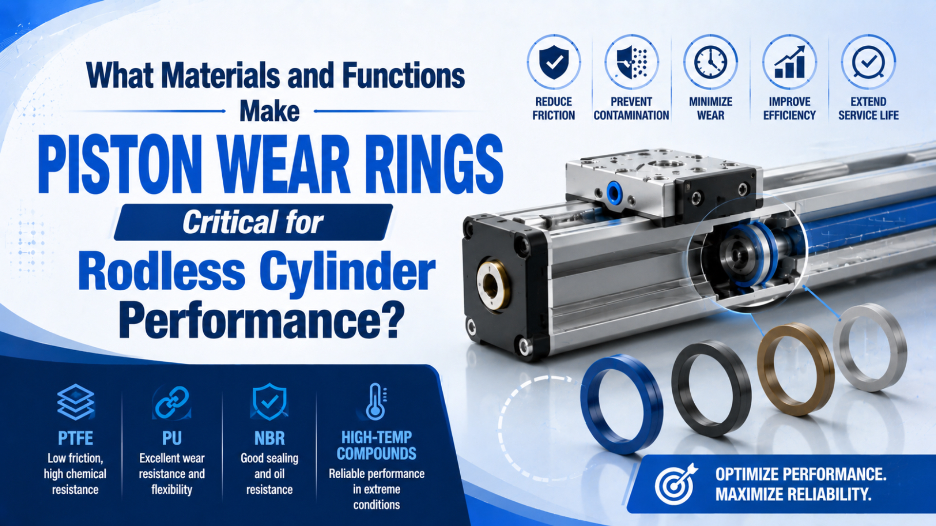
A piston wear ring is a non-metallic guide element that carries transverse load, keeps the piston centered, and prevents contact between the piston and cylinder bore. It protects the pressure seals by controlling alignment, but it is not a backup pressure seal. Material choice must match the actual ring profile, load, temperature, speed, media, mating surface, and groove geometry (SKF, 2026). That distinction is especially important in a mechanically coupled rodless cylinder. The external carriage can apply offset loads and moments to the internal piston assembly, so a ring selected only by bore diameter may be wrong for the real load path. Use the exact cylinder manual and approved service kit as the primary specification. This guide therefore treats geometry, guidance, and sealing as related but distinct engineering functions.
Key Takeaways
- A piston wear ring guides and supports; the piston seal contains pressure.
- Rodless-cylinder load, center-of-gravity offset, mounting orientation, and end impact determine the guide demand.
- PTFE-based compounds, POM, polyamide or other high-modulus thermoplastics, and fabric composites serve different operating envelopes.
- A material’s bulk temperature range is not an installed wear-ring rating.
- One-sided wear is evidence of a load-path or alignment problem, not merely a request for a new ring.
- Replacement requires the correct profile, dimensions, material grade, joint style, clearances, and mating-surface condition.
From our analysis of the cited manufacturer literature, the most useful way to understand a wear ring is as a replaceable geometry-control component. It occupies the radial clearance before the piston body can touch the bore. If the load, ring compression, tolerance stack, or wear consumes that protective clearance, the pressure seal is forced to work in a tilted or eccentric assembly.
What Does a Piston Wear Ring Actually Do?
SKF defines guide or wear rings as elements that guide a cylinder piston or rod, withstand side loads, and prevent damaging metal contact. Trelleborg uses the same functional boundary: the ring absorbs transverse forces while guiding the moving member (SKF, 2026; Trelleborg, 2026).
The ring performs four related tasks:
- Guide the piston. It limits radial displacement and helps the piston travel concentrically through the bore.
- Carry transverse load. It distributes side load over a bearing area instead of allowing a metal edge to become the contact point.
- Separate metal surfaces. It prevents the piston body from scoring, galling, or transferring material to the tube.
- Protect the sealing system. Stable guidance helps the piston seal retain its designed contact pattern and extrusion clearance.
The fourth task is indirect. A wear ring does not normally replace the piston seal or intentionally stop pressure flow across the piston. Split guide rings may even include a joint gap as part of their installation and thermal-expansion design. Treating that component as a secondary seal can hide the real fault when a cylinder leaks internally.
For a broader map of the sealing system, see the industrial cylinder seal guide. It separates piston seals, rod seals, wipers, static seals, and guide rings by function.
Why Do Rodless Cylinders Need Stable Piston Guidance?
SMC’s MY3 selection method evaluates load mass, static moment, and dynamic moment at stopper impact, and requires the sum of the applicable guide-load factors to remain at or below 1. The catalog also warns that exceeding the guide-load factor can damage internal slide-table parts (SMC MY3 Catalog, 2026).
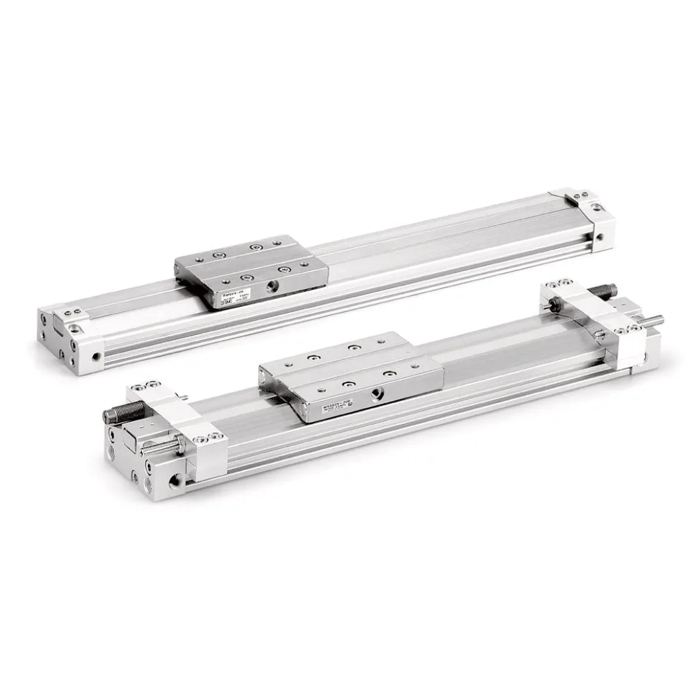
A rodless cylinder packages the piston, force-transmission connection, and carriage into one linear assembly. Transverse load is a force acting across the intended travel axis. The workpiece center of gravity may sit above or beside the carriage, converting load into pitch, yaw, or roll moment. Mounting on a wall or ceiling changes how gravity acts on the guide system, while a hard stop or poorly adjusted cushion adds a dynamic moment at the end of stroke.
The internal piston wear ring is only one part of this load path. Depending on the product, an external slide bearing, recirculating guide, or separate machine rail may carry much of the workpiece load. Never assume that upgrading the internal ring increases the actuator’s published allowable moment.
Before blaming ring material, check:
- Load mass and center-of-gravity offsets in all relevant axes.
- Mounting orientation and support spacing over the stroke.
- Static moments during dwell and dynamic moments during acceleration, deceleration, and impact.
- Carriage or external-guide play, alignment, and binding.
- Speed, cushion adjustment, shock absorber condition, and external stops.
- Piping forces, distorted mounting surfaces, and assembly preload.
The side-loading failure guide explains how offset forces reach the piston and guides. Correcting that path is usually more durable than fitting a harder ring into the same overloaded machine.
Which Wear-Ring Materials Fit Pneumatic Service?
Trelleborg’s pneumatic wear rings use a purpose-developed self-lubricating plastic, while its broader wear-ring range includes PTFE-based materials, high-modulus thermoplastics, and fabric composites for different loads. SKF likewise lists PTFE-based and thermoplastic guide-ring materials, with different load, speed, and temperature limits for each profile (Trelleborg Pneumatic Wear Ring, 2026; SKF, 2026).
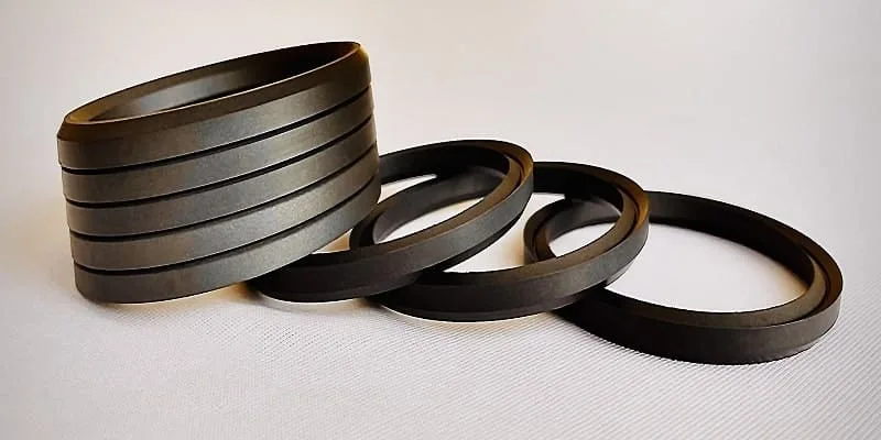
Use material families to build a shortlist, not to approve a substitution:
| Material family | Useful characteristics | Questions that decide suitability | Common reason to reject a casual substitution |
|---|---|---|---|
| PTFE-based compounds | Low friction, broad chemical options, and controlled sliding behavior; fillers change wear and strength | What filler and counterface are approved? What are the profile’s load and speed limits? Is dry pneumatic service permitted? | “PTFE” describes a family, not one load rating, expansion rate, or wear behavior |
| POM thermoplastic | Higher compressive capacity than many PTFE profiles, good machinability, and low moisture absorption | Are temperature, chemical exposure, speed, and lubrication compatible with the exact grade? | Higher stiffness can change clearance, friction, edge loading, and installation behavior |
| Polyamide or other high-modulus thermoplastic | Good bearing behavior and useful load capacity in selected designs | How do humidity, temperature, diameter, and dimensional change affect installed clearance? | Water absorption and thermal expansion can matter even when nominal dimensions match |
| Fabric-reinforced composite | High load capacity, good load distribution, and resistance to extrusion or deformation in suitable systems | Does the groove, surface finish, speed, and lubrication condition suit the composite? | A high-load hydraulic guide material is not automatically suitable for a fast, dry pneumatic rodless cylinder |
We found that none of the cited supplier documents treats a base polymer name as a complete selection. Polyurethane is widely used for dynamic seals and wipers, but that does not make every polyurethane grade a piston guide ring. Likewise, bronze-filled PTFE and PEEK can be valid engineered materials in specific profiles, yet the name alone does not establish suitability for a pneumatic cylinder.
The SKF F06 guide-ring sheet illustrates why copied maximum values are unsafe: listed material profiles have different specific-load and speed limits, and SKF explicitly says the general maximum conditions should not be used simultaneously (SKF F06 Datasheet, 2024). A bulk polymer range such as “PTFE to 260°C” therefore cannot be presented as the rating of an installed rodless-cylinder ring.
The correct material question is not “Which polymer is best?” It is “Which qualified ring profile keeps adequate protective clearance under this load spectrum without creating unacceptable friction, wear, or dimensional change?” That wording forces material, geometry, counterface, and duty to stay in the same decision.
How Do Wear Rings Protect Seals and Cylinder Bores?
SKF states that metal contact can score sliding surfaces and eventually lead to seal damage, leakage, and component damage. Parker also treats wear-ring compression and the complete tolerance stack as a critical measure of whether metal contact can occur (SKF, 2026; Parker WPT/WRT, 2025).
Consider the chain of events when guidance deteriorates:
- External load or misalignment pushes the piston away from the bore centerline.
- The guide ring carries that load and compresses locally.
- Wear, excessive load, insufficient bearing area, or lost clearance allows greater eccentricity.
- The piston seal runs with uneven contact pressure or excessive clearance on one side.
- Friction, extrusion risk, bypass leakage, and surface damage can increase.
- If the protective clearance is consumed, the piston body can mark the tube.
This is why replacing only the pressure seal can produce a repeat failure. If the guide ring, groove, piston, or bore no longer controls alignment, the new seal begins work in the same defective geometry. The honed cylinder tube guide explains why bore finish and geometry matter to sliding components.
It is also why internal leakage is not proof that the ring itself is “leaking.” Confirm the fault using the exact model’s test procedure, then inspect both the seal and guidance system. The internal leakage diagnostic guide covers the distinction between valve leakage, piston-seal bypass, and other air paths.
Wear Patterns Are Diagnostic Evidence
Parker explains that side load can move cylinder clearance to one side, creating uneven seal friction and possible scoring. Wear-ring and seal patterns should therefore be photographed, marked by orientation, and compared before the parts are discarded (Parker O-Ring Handbook, 2025).
| Finding during teardown | Likely mechanism to investigate | Required follow-up |
|---|---|---|
| Heavy wear on one arc of the ring | Persistent side load, offset moment, bore or piston misalignment | Check carriage load, guide alignment, mounting flatness, and support geometry |
| Edge wear or shaving | Ring tipping, wrong width or thickness, sharp groove edge, excessive gap, or installation damage | Measure the groove and ring; inspect chamfers, edges, joint, and assembly method |
| Uniform wear around the circumference | Normal duty, abrasive contamination, inadequate bearing area, or material mismatch | Compare dimensions with the service limit and inspect air cleanliness and counterface |
| Melting, smearing, glazing, or discoloration | Excessive interface temperature, speed, friction, chemical exposure, or unsuitable lubricant | Verify actual duty and compatibility; do not diagnose from ambient temperature alone |
| Cracks, embrittlement, swelling, or dimensional change | Chemical or thermal incompatibility, aging, moisture effect, or wrong material | Identify media and cleaners, retain a sample, and obtain material confirmation |
| Bore scoring or metallic transfer | Protective clearance was lost or debris became embedded | Measure bore damage and piston condition before authorizing a seal kit |
| New seal damaged on one side | Guidance, clearance, or alignment remained defective after repair | Stop repeated seal replacement and inspect the complete load path |
Do not infer root cause from color alone. Filled polymers and composites can vary in appearance, and service deposits can mask the original surface. Record the cylinder model, installation position, pressure, speed, load, cycle count if available, temperature, air condition, and recent machine changes with the physical evidence.
What Should Be Specified for a Replacement Wear Ring?
Parker’s tolerance-stack guidance shows that ring compression, radial clearances, rod or piston angularity, and bending all affect the remaining protection against metal contact. Replacement is therefore a dimensional and application-matching task, not simply a material upgrade (Parker WPT/WRT, 2025).
Tolerance stack means the combined effect of allowable dimensional variation across the bore, piston, groove, ring, and related parts. Each dimension may be individually acceptable while their worst-case combination leaves too little clearance before metal contact or too much freedom for the piston to tilt.
Our team found that the most reliable cross-supplier specification record keeps component identity, installed geometry, material grade, operating envelope, and verification criteria together. Confirm these 8 items before ordering or machining a replacement:
- Exact actuator identity: manufacturer, full model code, bore, stroke, revision, and serial or date code where applicable.
- Ring location and function: piston guide, carriage guide, rod guide, wear strip, or another part with a similar appearance.
- Installed dimensions: groove diameter, groove width, radial section, ring width, running clearance, and allowable wear limit from the drawing or manual.
- Profile details: split or continuous construction, straight or angle joint, chamfers, radii, pressure-relief features, and installation direction.
- Approved material grade: not only the base polymer, but also filler, reinforcement, hardness or modulus, and manufacturer compound code.
- Operating envelope: transverse load, moment, speed, stroke, duty, temperature at the interface, air quality, chemicals, washdown, and lubrication condition.
- Mating surfaces: bore material, coating, hardness, diameter, roundness, straightness, and surface-finish requirement.
- Assembly and verification: approved tools, edge protection, lubricant, cleanliness, torque values, post-repair leakage test, and loaded cycling criteria.
If an OEM service kit is available, it is usually the lowest-risk way to preserve the validated profile and compound. An alternate can be engineered, but matching nominal inside diameter alone is insufficient. Thermal expansion, joint-gap closure, compression, bearing area, and tolerance stack must be checked by someone responsible for the design.
For maintenance planning around the repair, use the complete pneumatic actuator maintenance checklist. It covers hazardous-energy control, baseline measurements, teardown evidence, and post-repair verification.
A Practical Inspection and Replacement Workflow
SMC cautions that guide-load factors must remain within the product’s specified range, while wear-ring suppliers require profile-specific operating limits. A sound workflow therefore corrects the load path before approving parts and verifies the complete actuator after assembly (SMC MY3 Catalog, 2026; SKF F06 Datasheet, 2024).
- Follow the machine’s approved hazardous-energy procedure and mechanically support any load that can move after pressure is vented.
- Record the symptom under controlled conditions: stroke time, pressure during motion, leakage path, carriage play, sound, impact, and product result.
- Recalculate the actual load and moments using the exact cylinder catalog, including center-of-gravity offsets and end-of-stroke dynamics.
- Inspect external guides, carriage bearings, stops, cushions, mounting, and load alignment before opening the cylinder.
- Mark orientation, photograph the installed components, and retain the old ring and seal as evidence.
- Measure the ring, groove, piston, and bore against the manufacturer limits; do not polish away evidence before inspection.
- Correct overload, alignment, contamination, surface damage, or installation problems before fitting approved parts.
- Reassemble using the model procedure, then test leakage, full stroke, carriage guidance, sensors, cushioning, and loaded operation against recorded acceptance criteria.
No universal “2 million cycles” or “replace every 2 years” interval applies to all piston wear rings. Inspection frequency and replacement limits should come from the exact model, machine risk, duty, environment, condition trend, and failure history.
FAQs About Piston Wear Rings
Are piston wear rings the same as piston seals?
No. A piston wear ring guides the piston, carries side load, and prevents metal contact. A piston seal controls pressure bypass between cylinder chambers. A worn guide ring can damage a seal indirectly by allowing eccentric motion, but the guide ring should not be treated as a backup pressure seal.
Can a harder wear-ring material increase rodless-cylinder load capacity?
Not by itself. The actuator’s allowable load and moment also depend on the carriage, external guide, piston, tube, connection, mounting, cushioning, and complete tolerance stack. Do not exceed the published cylinder limits unless the manufacturer has approved a redesigned assembly.
Which material is best for a pneumatic piston wear ring?
There is no universal best material. PTFE-based compounds, POM, high-modulus thermoplastics, and fabric composites trade friction, load capacity, wear, chemical compatibility, dimensional stability, and speed differently. Select the exact qualified profile for the cylinder, counterface, environment, and duty.
When should a rodless-cylinder wear ring be replaced?
Replace it at the manufacturer’s dimensional or condition limit, or when damage makes continued service unacceptable. One-sided wear, excessive carriage or piston play, scoring, heat damage, cracking, and repeat seal failure require root-cause inspection; they do not establish one universal cycle interval.
Can a generic ring replace the OEM wear ring?
Only after engineering verification. The replacement must match the required profile, dimensions, joint, material grade, thermal behavior, bearing area, clearances, mating surface, and operating envelope. A matching bore diameter or polymer name alone is not enough to prove interchangeability.
What Should You Remember About Piston Wear Rings?
Piston wear rings matter because they preserve the geometry in which a rodless cylinder’s seals and sliding surfaces can work. Their critical function is guidance under transverse load—not secondary sealing. Choose them from the actual load spectrum, profile data, groove and bore geometry, environment, and manufacturer limits, then use the removed parts to diagnose why wear occurred.
Jason Tan prepared this guide from a manufacturing, tolerance, and inspection perspective. The Jason Tan author page provides the engineering background behind this technical library.
Source Notes and Retrieval Dates
- SKF Seals Product Range, guide-ring function, pneumatic applicability, materials, and profile limits. Retrieved 2026-07-18.
- SKF F06 Guide Ring Datasheet, material-specific operating indications and warning against combining maximum values. Retrieved 2026-07-18.
- Trelleborg Pneumatic Wear Ring, pneumatic guide-ring material and functional characteristics. Retrieved 2026-07-18.
- Trelleborg Slydring and Wear Ring, transverse-force, guidance, metal-separation, and material-family descriptions. Retrieved 2026-07-18.
- SMC MY3 Mechanically Jointed Rodless Cylinder Catalog, guide-load-factor method, load and moment selection, and overload caution. Retrieved 2026-07-18.
- Parker WPT/WRT Series Wear Rings, wear-ring compression, tolerance stack, and metal-contact clearance. Retrieved 2026-07-18.
- Parker O-Ring Handbook, side-load effects on clearance, friction, leakage, and scoring. Retrieved 2026-07-18.