

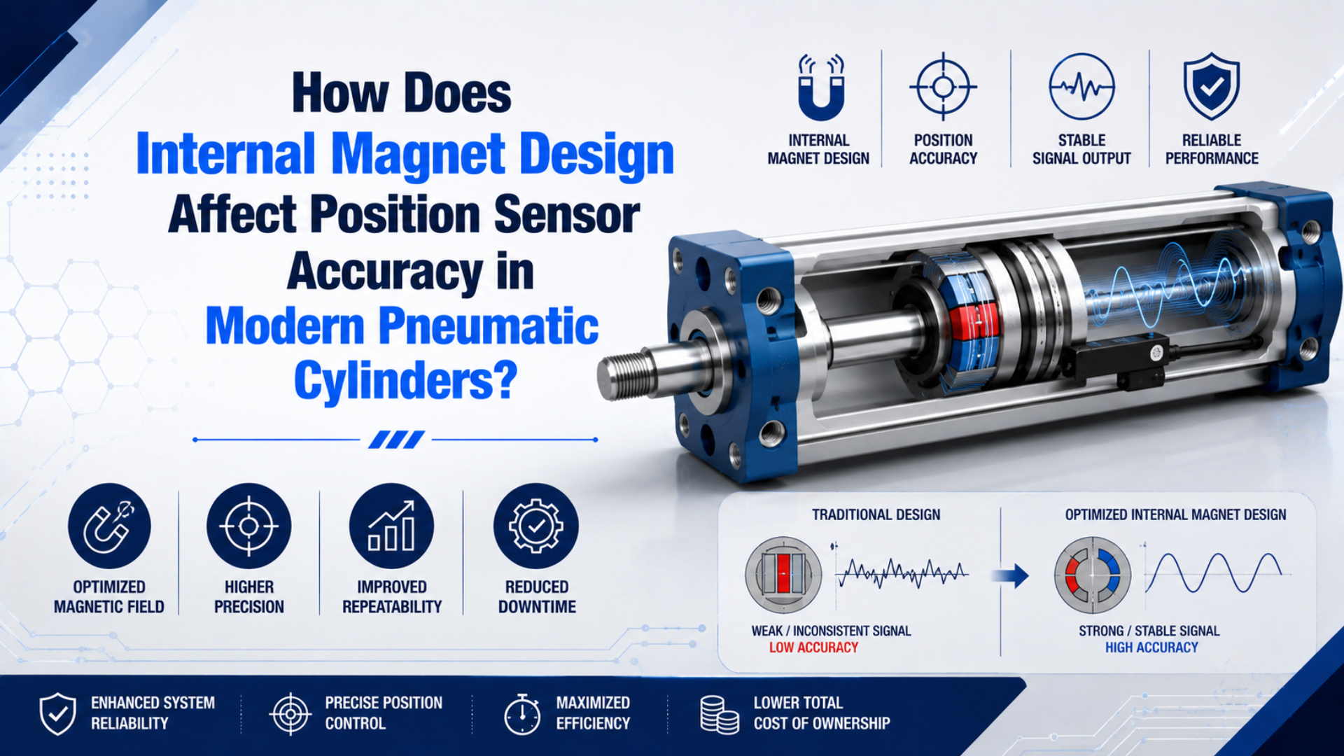
Internal magnet design affects position sensor accuracy by shaping the magnetic field that reaches the sensor. Magnet geometry, magnetization direction, strength, air gap, piston alignment, and cylinder-wall construction can change the switch operating range, ON/OFF points, hysteresis, and the response curve of an analog magnetic sensor. They do not, by themselves, determine the positioning accuracy of the pneumatic cylinder or the machine.
That distinction matters. A reed or solid-state cylinder switch normally confirms that the piston has entered a detection zone. An analog magnetic sensor can estimate position over a stated measuring range. Neither signal proves that the tooling, carriage, or workpiece reached the same coordinate unless the complete mechanical and control system has been tested.
In our experience, the fastest way to avoid a sensing mismatch is to define the PLC decision first: endpoint confirmed, zone entered, or position measured. The magnet and sensor can then be evaluated against that specific job.
Key Takeaways
- Treat the piston magnet and external sensor as a matched sensing system, not as interchangeable parts.
- For discrete switches, evaluate operating range, hysteresis, repeatability, response time, and mounting tolerance.
- For analog sensors, keep resolution, repeatability, linearity error, and machine accuracy separate.
- Stronger magnetic material does not automatically produce better position accuracy.
- Verify the signal at production speed, load, temperature, and electrical environment before approving the design.
What Does the Internal Piston Magnet Actually Control?
The internal piston magnet controls the field available to the sensor outside the pressure boundary. As the piston moves, the field at the sensor rises, changes direction, and falls. A compatible switch changes state when that field crosses its operating threshold. An analog magnetic sensor samples the field over a detection zone and converts its response into a position-related output.
The magnet therefore influences four practical results:
- Detection margin is the usable field that reaches the sensor through the piston, air gap, cylinder wall, and sensor housing.
- Operating window is the length of piston travel over which a discrete switch remains ON.
- Switch-point stability is the consistency of the ON and OFF points as direction, temperature, installation, and speed change.
- Analog response shape is the relationship between piston travel, magnetic field, and the sensor’s reported output.
SMC defines an auto-switch operating range as the ON length produced by piston movement. Its guide states that the range depends on both the magnet’s magnetic force and switch sensitivity, and may vary with environmental conditions (SMC Auto Switch Guide, accessed July 18, 2026). This is why a catalog mounting dimension is a starting point rather than a machine acceptance result.
The internal magnet does not control guide clearance, mounting-bracket flex, seal friction, pneumatic compressibility, valve response, load movement, or mechanical stop repeatability. Those factors remain part of the machine-level error budget. If the application needs measured position rather than a simple arrival signal, use the broader pneumatic cylinder position sensing guide to select the correct sensor class.
Which Accuracy Terms Should Engineers Keep Separate?
The word “accuracy” is too broad for a magnetic cylinder sensor specification. Engineers should identify the actual error term before comparing magnets, switches, or actuator brands.
| Term | What it describes | Why the magnet matters | What it does not prove |
|---|---|---|---|
| Operating range | Distance over which a discrete switch remains ON | Field strength, shape, air gap, and switch sensitivity set the usable window | Exact piston or tooling coordinate |
| Hysteresis | Difference between the operating point and release point when direction reverses | Field gradient and switch threshold affect the two crossing points | Machine backlash or total positioning error |
| Repeatability | Variation when the same approach is repeated under stated conditions | Field stability and mechanical retention can affect the result | Absolute accuracy to a calibrated datum |
| Resolution | Smallest reported change of a continuous sensor | Field response and sensor electronics influence the usable signal | Linearity or machine accuracy |
| Linearity error | Deviation of sensor output from its reference response | Magnet/drive compatibility and field profile can contribute | Load-position accuracy after mechanics and control are included |
For one SMC auto-switch guide, the listed reference hysteresis is 2 mm or less for reed switches and 1 mm or less for solid-state switches. SMC also warns that hysteresis can fluctuate with the operating environment. Those figures describe the covered switch families and must not be copied as universal values for every cylinder and switch combination.
The same caution applies to analog devices. SICK’s MPS-G analog sensor lists, for one product family, a typical resolution of 0.01 mm, typical linearity of 0.3 mm, and typical repeatability of 0.05 mm. It also notes that deviations are possible depending on the drive (SICK MPS-G operating instructions, accessed July 18, 2026). A 0.01 mm resolution value therefore cannot be advertised as 0.01 mm cylinder positioning accuracy.
How Do Magnet Geometry and Magnetization Affect the Signal?
Magnet geometry and magnetization determine how the field is distributed around the piston. The useful design is the one validated with the intended cylinder wall and sensor—not simply the magnet with the highest surface field.
Ring and Segmented Magnet Arrangements
A ring-shaped arrangement can provide a field around the cylinder circumference and make sensor mounting available in more than one slot or orientation. A segmented or localized arrangement can concentrate the field near intended sensor locations. Both approaches can work. Neither is universally more accurate.
The engineering questions are:
- Where can the sensor be mounted on the finished cylinder?
- Is the magnet magnetized axially, diametrically, radially, or in a custom pattern?
- Does the sensor measure one field axis or more than one?
- How much radial and axial misalignment can the assembly tolerate?
- Does the response remain usable at the minimum and maximum production temperatures?
SICK’s MPS-G, for example, uses two sensor elements to measure field strength in two directions and can detect axially or diametrically magnetized encoder magnets. That is a product-specific compatibility feature, not proof that every Hall-effect sensor accepts every piston magnet.
Field Gradient Matters More Than a Single Strength Number
A discrete switch changes state where its threshold intersects the magnet’s field profile. If the field changes steeply with piston travel near the threshold, a small position change produces a clear signal change. If the field changes slowly, small variations in sensor position, temperature, or threshold can shift the observed switching point more noticeably.
This does not mean that the steepest possible gradient is always best. The switch still needs enough operating range to accommodate installation tolerance, piston overtravel, vibration, and the required PLC timing. A narrow window can be precise in a bench test yet unreliable on a production machine if the sensor bracket moves or the piston rebounds.
Mechanical Retention Preserves the Designed Field
The magnet must remain in its intended position and orientation relative to the piston. Retention features, adhesive compatibility, molding method, piston material, shock load, and thermal cycling all matter. Magnet movement changes the field location even if the magnet material itself has not weakened.
During failure analysis, compare the actual switch position with the documented commissioning position. If every switch point has shifted in the same direction, inspect the sensor bracket and piston assembly before blaming the PLC.
Does Stronger Magnet Material Improve Sensor Accuracy?
Stronger magnet material can increase field margin, but it does not create a predictable millimeter accuracy improvement. Ferrite, neodymium-iron-boron, and samarium-cobalt magnets have different magnetic, temperature, corrosion, cost, and manufacturing characteristics. The correct selection depends on the required field at the sensor after the entire magnetic circuit is assembled.
A stronger magnet may help when the cylinder wall, sensor gap, or selected switch needs more field. It may also be unnecessary if the existing design already provides adequate margin. For an analog sensor, a different field profile can move the usable measuring zone or require a new teach-in. For a discrete switch, it can widen the operating range rather than make the switching coordinate inherently more accurate.
Avoid material-only comparison tables such as “ferrite equals several millimeters while rare earth equals tenths of a millimeter.” No defensible universal conversion exists. Request compatibility data for the exact cylinder bore, piston magnet, sensor model, slot, and temperature range.
From our analysis of manufacturer documentation, the usable specifications are attached to defined sensor and actuator combinations. They are not attached to magnet material alone.
How Do the Cylinder Wall, Air Gap, and Installation Change Detection?
The sensor responds to the field that reaches its sensing element, not to the magnet’s isolated laboratory rating. The complete path includes the piston construction, clearance, cylinder tube, mounting slot, sensor housing, and final sensor-to-piston distance.
The main installation variables are:
- Cylinder-wall construction: material, thickness, grooves, and nearby magnetic components affect the field at the sensor.
- Radial gap: piston clearance, wall thickness, sensor recess, and bracket position add distance between magnet and sensor.
- Axial placement: the sensor must be located so the required piston position lies inside a stable part of the operating window.
- Nearby steel: brackets, fasteners, guards, chips, or other magnetic material can disturb the local field.
- Cylinder-to-cylinder spacing: adjacent actuators and their magnets can matter in compact assemblies.
SMC advises users to align the switch’s most sensitive position with the center of the magnet as a starting point, then adjust on the actual machine. Its precautions also warn that accumulated iron particles or nearby magnetic material can weaken the effective field and cause malfunction. These are installation controls, not reasons to claim a better magnet material will solve every sensing problem.
How Do Temperature and External Magnetic Fields Affect Reliability?
Temperature can change magnet output, sensor electronics, cable behavior, mechanical dimensions, and the pneumatic actuator itself. A magnet material’s reversible temperature coefficient is only one input. It cannot be converted directly into millimeters of position drift without the field geometry, sensor threshold or transfer curve, mounting stack, and test conditions.
For a new design, verify three temperature limits:
- the magnet and retention system remain suitable at the maximum piston temperature;
- the sensor and cable stay within their operating ratings;
- the switch point or analog output remains acceptable after the complete assembly stabilizes at temperature.
External magnetic fields require similar system thinking. SMC warns that magnetic fields can cause auto-switch malfunction or demagnetize actuator magnets. Its magnetic-field-resistant switch guidance also distinguishes between AC welding fields and DC fields; protection for one condition is not automatically immunity to the other. Near welders, induction equipment, large conductors, or electromagnetic lifters, specify the welding/current type and follow the sensor manufacturer’s separation and compatibility rules.
Cable routing and electrical noise still matter for solid-state and analog outputs. Keep sensor wiring away from power cables where practical, verify grounding and shielding, and inspect the actual PLC value. A stable LED with an unstable analog input points to a different fault branch than a switch that changes state as the welding current starts.
Are Sensing Magnets the Same as Magnetic Coupling Magnets?
No. In a standard magnetic-sensing cylinder, the piston magnet provides a field that an external switch or sensor can detect. In a magnetically coupled rodless cylinder, a magnetic assembly may also transfer force through the sealed tube to an external carriage. Coupling force and position sensing are separate engineering functions even when both rely on permanent magnets.
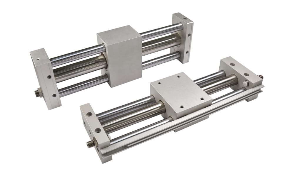
Do not assume that a coupling-force rating predicts switch performance. A rodless cylinder can have adequate magnetic coupling yet an incorrectly mounted sensor. It can also have a reliable sensor signal while the carriage has mechanically decoupled. The controller should detect those as different faults when the application risk justifies it.
For the force-transfer mechanism, see how a magnetic rodless cylinder works. For product geometry and available sensing options, review the rodless cylinder range with the exact sensor part number.
How Should You Diagnose an Unstable Switch Point?
An unstable switch point is a system symptom. Change one variable at a time and record the direction of approach, because hysteresis makes forward and reverse results different.
Our team found that the clearest diagnostic sequence treats the sensor LED, PLC input, piston position, and tooling datum as separate checkpoints. This separation prevents teams from replacing a cylinder when the real problem is a loose bracket, incorrect input wiring, or movement after the piston.
| Symptom | Likely branches | First checks |
|---|---|---|
| Switch never turns ON | Wrong sensor, inadequate field margin, excessive gap, wiring fault | Confirm cylinder/switch compatibility, voltage, output type, and mounting slot |
| Switch turns ON only in a narrow spot | Low margin, misalignment, nearby magnetic material | Sweep slowly, inspect bracket and chips, compare with catalog range |
| ON point repeats but OFF point moves | Hysteresis, piston rebound, approach-direction change | Record both directions and actual motion at production speed |
| Signal changes near a welder | External magnetic field or electrical noise | Correlate with welding cycle, inspect sensor type, cable routing, and PLC value |
| Every position shifts after repair | Sensor moved, piston/magnet orientation changed, wrong replacement part | Compare part numbers and recorded mounting dimensions |
| Analog value is noisy | Wiring, grounding, external fields, metallic debris, wrong teach-in | Inspect signal at the controller and repeat the manufacturer’s teach routine |
If the sensor reports a stable position but the tooling is wrong, move the investigation to coupling play, guide wear, stop deflection, load movement, or the pneumatic control loop. The article on integrating feedback sensors with pneumatic actuators explains how to separate sensor error from machine-level positioning error.
What Should Be Verified Before Production Release?
Commission the cylinder, magnet, sensor, wiring, PLC input, and mechanics as one assembly. A hand sweep during installation is useful, but it does not replace a loaded production test.
- Record the complete cylinder and sensor part numbers.
- Confirm the sensor is approved for the cylinder bore, slot, and built-in magnet option.
- Verify supply voltage, PNP/NPN or analog output, connector pinout, and PLC input type.
- Move the piston slowly in both directions and mark the ON and OFF positions.
- Measure the usable operating window and directional hysteresis rather than one LED position.
- Run at minimum and maximum production speed with the real load and cushion settings.
- Check the PLC signal during vibration, adjacent-cylinder motion, and the normal welding or motor cycle.
- Repeat after thermal stabilization at relevant operating temperatures.
- Confirm that the sensed piston position corresponds to the actual carriage, tooling, or workpiece datum.
- Save the final sensor location, teach parameters, measured results, and acceptance limits.
For a continuous sensor, record resolution, repeatability, linearity, update rate, measuring range, and out-of-range behavior separately. If the axis must stop or hold at variable positions, the sensor also needs a proportional valve, controller, tuning method, and machine acceptance test. A sensor signal alone is not closed-loop positioning.
What Data Should an RFQ Include?
Send the supplier enough information to verify magnetic and electrical compatibility before quoting.
| RFQ item | Required detail |
|---|---|
| Actuator | Cylinder series, bore, stroke, piston/magnet option, rodless or rod type |
| Sensing task | End confirmation, zone detection, analog position, or control feedback |
| Sensor | Preferred technology, exact model if replacing, slot and mounting direction |
| Controller | Supply voltage, PNP/NPN, analog range, IO-Link, sampling or response requirement |
| Mechanics | Required process datum, guide type, load, speed, direction of approach, stops |
| Environment | Temperature, washdown, chips, vibration, nearby steel, welding/current type |
| Acceptance | Operating window, hysteresis, repeatability, allowable missed or false signals |
Ask for the compatible cylinder/sensor matrix and the conditions behind every stated value. If the request only says “0.1 mm accuracy,” return it for clarification: does that mean switch repeatability, sensor linearity, piston position, carriage position, or workpiece position?
Conclusion
Internal magnet design matters because it determines the field profile and margin available to a cylinder-mounted sensor. A well-matched design produces a stable operating window or a usable analog response across the specified environment. It does not turn an open-loop pneumatic cylinder into a precision positioning axis.
Select the magnet, cylinder, and sensor as a documented combination. Keep operating range, hysteresis, repeatability, resolution, linearity, and machine accuracy separate. Then verify the complete assembly at production speed, load, temperature, and electrical conditions.
FAQs About Internal Magnet Design and Position Sensor Accuracy
Does a stronger piston magnet always improve position sensor accuracy?
No. A stronger magnet can increase detection margin or widen a switch’s operating range, but it does not create a predictable improvement in position accuracy. The result depends on magnet geometry, cylinder wall, sensor sensitivity, mounting gap, temperature, and the sensor’s operating principle.
What is the difference between operating range and hysteresis?
Operating range is the distance over which a discrete cylinder switch remains ON as the piston moves. Hysteresis is the difference between the switch’s operating and release positions when motion reverses. Both must be checked with the exact cylinder and switch combination.
Can a reed switch provide precise continuous piston position?
No. A reed switch provides a discrete ON/OFF signal when the piston magnet enters its detection zone. It can confirm an endpoint or fixed zone, but it does not report continuous position. Use a compatible analog sensor, transducer, or encoder when the controller needs a measured position value.
Does 0.01 mm sensor resolution mean 0.01 mm cylinder accuracy?
No. Resolution is the smallest position change a sensor reports. Linearity error, repeatability, mounting, guide clearance, load movement, pneumatic behavior, and control performance still affect the cylinder or machine result.
How should magnetic cylinder sensors be used near welding equipment?
Identify whether the external field is AC or DC, select a sensor and cylinder combination approved for that environment, follow the manufacturer’s spacing rules, and verify the PLC signal during the real welding cycle. A generic shielded magnet claim is not enough.
External Technical References
- SMC Auto Switch Guide, operating range, most-sensitive position, hysteresis, switch types, and magnetic-field-resistant switch guidance. Accessed July 18, 2026.
- SMC Reed Auto Switch Operation Manual D-A3, reed-switch operating principle and directional hysteresis. Accessed July 18, 2026.
- SMC Auto Switch Precautions, external magnetic fields, iron debris, wiring, environmental limitations, and welding-field precautions. Accessed July 18, 2026.
- SICK MPS-G with Analog Output Operating Instructions, magnet detection principle, teach-in, measuring range, resolution, linearity, and repeatability. Accessed July 18, 2026.
- Temposonics Magnetostriction, waveguide, position magnet, strain pulse converter, electronics, and time-of-flight measuring principle. Accessed July 18, 2026.