

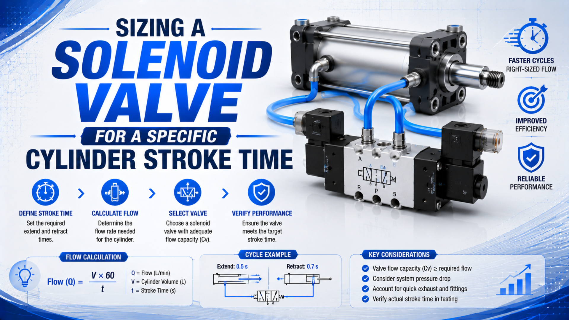
Size the solenoid valve from the larger free-air demand of the cylinder’s extension and retraction strokes, calculated over the required travel time. Then select a directional valve using the manufacturer’s compressed-air data at the real inlet and outlet pressures. Finally, verify the complete supply and exhaust paths on the machine. A 63 mm bore cylinder with a 300 mm stroke and a 0.5-second extension at 6 bar(g) needs about 777 L/min, or 27.4 SCFM, before allowance for tubing volume and operating uncertainty.
Key Takeaways
- The 63 mm example needs 27.4 SCFM for extension, not a four-digit SCFM value.
- Calculate single-rod extension and retraction separately.
- Match demand to one manufacturer’s pneumatic rating method.
- Electrical valve response and cylinder travel time are different intervals.
What Inputs Define the Motion Requirement?
Parker’s published 1-second sizing example begins with five defined values: cylinder area, 12-inch stroke, 80 psig supply, compression factor, and allowed pressure drop (Parker Hannifin, Pneumatic Valve Products Engineering Data, accessed 2026). Likewise, a 300 mm stroke completed in 0.5 second establishes 600 mm/s average piston speed, but the remaining inputs decide the air demand.
Write down the operating point before opening a valve catalog:
| Input | What to use | Why it changes the result |
|---|---|---|
| Bore and rod diameter | Actual cylinder drawing | Define cap-end and rod-end areas |
| Stroke | Pressurized travel, in mm or in | Defines chamber displacement |
| Extend and retract time | Separate production limits | The two directions may have different targets |
| Minimum valve-inlet pressure | Dynamic pressure, not compressor setpoint | Determines available pressure ratio |
| Load and orientation | Force direction through the stroke | Affect breakaway and required chamber pressure |
| Tube and fitting geometry | ID, length, bends, couplers | Add fill volume and pressure loss |
| Exhaust hardware | Speed controller and silencer model | Can limit flow as strongly as the inlet path |
The target should be travel time, not merely PLC command duration. Decide whether the specification runs from electrical command to end-sensor confirmation or only from first piston motion to arrival. Those definitions produce different acceptance results. If the PLC timer includes valve switching and pressure buildup, reserve those intervals explicitly instead of pretending the cylinder receives the full 0.5 second.
In our application reviews, the most useful first question is usually, “What pressure remains at the valve while the cylinder is moving?” A static regulator reading can look healthy even when a shared manifold, small coupler, or filter causes the usable pressure to collapse during the stroke.
For force and velocity inputs that must be settled before valve selection, see the guide to calculating pneumatic cylinder piston velocity.
How Do You Calculate Extension and Retraction Flow?
NIST defines one standard atmosphere as 101,325 Pa and converts 1 cubic foot per minute to 28.31685 L/min (NIST, Pressure and Gas Flow Unit Conversions, accessed 2026). These two reference values prevent common mistakes: using gauge pressure as absolute pressure and converting cubic inches per second directly to SCFM without the required time and volume factors.
For a single-rod cylinder, calculate the two effective areas separately:
where:
- is cap-end piston area in mm² or in²;
- is rod-end annular area in the same units;
- is bore diameter;
- is rod diameter.
Multiply each area by stroke to obtain its geometric chamber volume:
For a transparent first-pass estimate at approximately equal reference and operating temperatures, convert that volume to equivalent free air with absolute pressure:
Here, is equivalent free-air flow, is the chamber volume, is the allowed stroke time, is cylinder filling pressure on an absolute basis, and is the chosen reference pressure. State the reference conditions whenever you report SCFM or standard L/min because standard-volume conventions can differ.
Equivalent free-air flow is the amount of air expressed at stated reference conditions that must enter the chamber during the allowed interval. This equation estimates its average demand. It is not a valve flow equation. Real chamber pressure rises during motion, the exhaust side retains back pressure, line volume also fills, and temperature is transient. Consequently, use the result to establish demand, then use the valve manufacturer’s gas-flow method to select hardware.
What if the cylinder is double-rod or rodless? Use the actual effective areas and chamber volumes from its data sheet. Don’t assume both sides are identical merely from the product family name.
Worked Example: A 63 mm Cylinder With a 0.5-Second Stroke
At 6 bar(g), the absolute-to-atmospheric pressure ratio is about 6.922 when 1.01325 bar is used as the atmospheric reference (NIST, accessed 2026). For a 63 mm bore and 300 mm stroke completed in 0.5 second, that ratio produces an ideal extension demand of about 776.7 L/min, or 27.43 SCFM, before line volume is added.
Use these defined inputs:
- bore mm;
- illustrative rod diameter mm;
- stroke mm;
- target time s in both directions;
- filling pressure bar(g);
- equal operating and reference temperature for this first pass.
Extension calculation
The cap-end area and volume are:
That chamber holds about 6.473 standard litres at the stated pressure ratio. Dividing by 0.5 second gives 12.946 standard L/s, equivalent to 776.7 L/min or 27.43 SCFM.
Retraction calculation
The 20 mm rod reduces the rod-end area to 2,803.09 mm² and its chamber volume to 0.8409 L. Under the same assumptions, retraction requires about 698.5 L/min or 24.67 SCFM. Extension controls the initial valve-capacity check because it has the larger demand.
| Direction | Effective area | Geometric volume | Equivalent free air per stroke | Average flow during 0.5 s |
|---|---|---|---|---|
| Extension | 3,117.25 mm² | 0.9352 L | 6.473 L | 776.7 L/min, 27.43 SCFM |
| Retraction | 2,803.09 mm² | 0.8409 L | 5.821 L | 698.5 L/min, 24.67 SCFM |
The rod diameter is an explicit assumption, not a hidden default. Replace 20 mm with the actual catalog value. Also add tube and fitting dead volume when the valve is remote from the cylinder; that volume must pressurize on every reversal even though it doesn’t contribute to piston travel. See the separate dead-volume and cylinder response-time analysis for that transient effect.
This example exposes a unit trap. Multiplying cylinder volume by a pressure ratio and dividing by seconds produces volume per second in the original volume unit. If the volume is in cubic inches, conversion to SCFM requires multiplication by 60 and division by 1,728. Attaching an SCFM label before that conversion can inflate the answer by nearly 29 times.
How Do You Convert Demand Into a Catalog Valve Selection?
Parker’s published pneumatic sizing example uses a 3.25-inch bore, 12-inch stroke, 80 psig supply, and 1-second stroke to calculate a required Cv of 1.06 (Parker Hannifin, Pneumatic Valve Products Engineering Data, accessed 2026). Convert demand by applying the selected manufacturer’s pneumatic method at the real pressures, not by treating air as an incompressible liquid.
Don’t convert 27.43 SCFM to Cv with a liquid-flow shortcut. Air can be subsonic or choked, so upstream absolute pressure, downstream absolute pressure, temperature, and the test convention matter. ISO 6358-1 defines steady-state methods for pneumatic components with fixed or variable internal flow paths (ISO 6358-1:2013, confirmed 2022). A catalog may therefore provide one or more of these:
| Published data | How to use it |
|---|---|
| Flow curve in L/min or SCFM | Read capacity at the stated inlet and outlet pressures and standard conditions |
| Cv or Kv | Use the manufacturer’s pneumatic equation, table, or selector |
| Sonic conductance and critical pressure ratio | Apply the manufacturer’s ISO 6358 calculation or sizing software |
| Separate directional-path ratings | Check the working supply and exhaust paths, not only the highest headline number |
Port thread is a connection specification. It isn’t a flow rating. Two 1/4-inch 5/2 valves can have different spool geometry, pilot arrangements, internal manifolds, and exhaust capacity. Use the Cv guide for coefficient fundamentals, then return to one manufacturer’s compressed-air method for the actual model.
A sound catalog decision follows four steps:
- Use the higher directional demand, 776.7 L/min in this example.
- Set the minimum expected valve-inlet pressure during motion.
- Set a defensible downstream pressure or allowed pressure loss for the catalog method.
- Choose a valve whose relevant flow path meets the result, then verify coil voltage, function, duty rating, environmental protection, and pilot-pressure limits.
The valve function must also match the circuit. A typical double-acting cylinder needs a 4-way directional function, commonly implemented as a 5/2 or 5/3 valve. A high-flow 2/2 process valve doesn’t replace that directional logic. For port functions, see how a 4-way 5-port valve controls a cylinder.
Why Must Supply and Exhaust Paths Be Sized Together?
ISO 6358-3 covers systems of components and piping and includes both subsonic and choked compressible flow (ISO 6358-3:2014, confirmed 2025). Size the paths together because every stroke uses one supply route and the opposite exhaust route at the same time. The installed tube, fittings, speed controls, manifold, and silencers therefore act as a series of restrictions.
On a 5/2 circuit, extension might use supply path P to A and exhaust path B to EA. Retraction uses P to B and A to EB. If the catalog publishes different ratings by path, check both combinations. A small exhaust silencer or nearly closed meter-out speed controller can dominate one direction even when the inlet path is ample.
Think of valve capacity as a path property, not a product label. The controlling capacity for a stroke is the combination of one supply route and the opposite exhaust route at that moment. This is why one cylinder direction can miss time while the reverse direction passes with the same valve body.
Use meter-out control as the usual starting arrangement for a double-acting cylinder with a resisting or overhauling load. It meters the exhaust and maintains back pressure against a load that wants to run ahead. Meter-in has legitimate applications, but it doesn’t automatically provide precision positioning and can be unstable with an assisting load. The companion flow-control valve sizing guide covers installation choices in more depth, while the pressure-drop troubleshooting guide helps locate a restriction that appears only during flow.
Add Margin From Real Uncertainty, Not a Fixed Multiplier
Parker’s example tables distinguish allowed pressure drops of 2, 5, and 10 psi rather than prescribing one universal percentage (Parker Hannifin, accessed 2026). Add margin by recalculating named operating cases. That is more defensible than multiplying every answer by 1.2, 1.3, or 1.5 without identifying what the extra capacity represents.
Build margin through scenarios. Recalculate the selection at the lowest inlet pressure expected during the production cycle. Include tube volume. Check the actual rod size. Use the worst allowed stroke time, not an informal average. If another actuator overlaps, model that overlap. Then choose the next catalog size that meets those stated cases.
| Uncertainty | Better engineering response |
|---|---|
| Shared supply pressure varies | Size at the measured minimum dynamic pressure |
| Valve is remote from cylinder | Add both pressurized line volumes |
| Production load changes | Verify force margin and test the maximum load |
| Faster future recipe is known | Calculate that documented time as a second operating case |
| Catalog data use different standard conditions | Normalize units or use the manufacturer’s selector |
| Simultaneous actuators are possible | Combine only the demand that truly overlaps in time |
Why avoid a blanket factor? It can still leave the circuit undersized when the real problem is pressure collapse. In another machine, it can produce a valve that is needlessly large, more expensive, and harder to meter smoothly. A named uncertainty can be tested. A mystery percentage cannot.
For an installed system that seems to have sufficient catalog capacity but still runs slowly, use the valve flow and system bottleneck guide to separate valve restriction from the rest of the circuit.
How Do Multiple Cylinders Change the Calculation?
CAGI recommends limiting total pressure drop from compressor discharge to the point of use to no more than 10% in a well-designed system (CAGI, Working With Compressed Air, accessed 2026). For multiple cylinders, add only the directional flow demands that overlap in time, then check that peak against the common regulator, manifold, and feed line.
Don’t add every cylinder’s flow unless every stroke can occur at the same time. Build a simple timing table from the PLC sequence:
| Time window | Active strokes | Flow used for shared-path sizing |
|---|---|---|
| A extends alone | A extension | |
| A extends while B retracts | Two simultaneous strokes | |
| B dwells while C extends | C only | |
| All cylinders dwell | No motion flow | Leakage and control-air demand only |
Use the largest concurrent total to check the common regulator, manifold feed, and supply tube. Each branch valve still needs its own directional path check. For sequential movements, sizing the common path from the sum of all theoretical strokes exaggerates demand. For overlapping movements, sizing from only the largest single cylinder understates it.
If dynamic pressure at the manifold falls during the overlap, first check the upstream restriction and storage strategy. A local receiver can support a short peak only when its usable pressure range, refill time, check-valve arrangement, and safety requirements are calculated. It isn’t a substitute for an undersized regulator or feed line.
How Do You Verify Stroke Time on the Machine?
CAGI reports that each 2 psig of excess compressor discharge pressure increases compressor power by about 1% (CAGI, Working With Compressed Air, accessed 2026). Verify the stroke with timestamps and dynamic pressure at the machine. Raising the plant setpoint to rescue one slow actuator instead hides a local restriction and creates an ongoing energy penalty elsewhere.
Commission the chosen valve with the production load, real sequence, and normal supply conditions:
- Record electrical command, first motion, and end-sensor timestamps separately.
- Log pressure at the valve inlet and both cylinder ports during each stroke.
- Measure extension and retraction several times after the system reaches operating temperature.
- Confirm cushion needles and speed controllers are set for stable deceleration, not just the shortest possible time.
- Repeat the test during the machine’s highest simultaneous air demand.
The timing traces separate three intervals:
- Valve switching delay: electrical command to establishment of the new flow path.
- Pressure-build delay: flow-path change to piston breakaway.
- Travel time: first piston motion to end position.
A datasheet valve response time describes the first interval under stated test conditions. It doesn’t include filling a long tube, building enough cylinder pressure to overcome load and friction, or moving the piston through 300 mm. Therefore, a 20 ms valve response doesn’t prove a 500 ms command-to-sensor requirement will pass. The solenoid valve response-time measurement guide explains the electrical and pneumatic timing boundaries in detail.
If the inlet pressure holds but the filling port rises slowly, inspect the valve path, tube, fitting bore, and supply-side controller. If inlet pressure sags, move upstream to the regulator, filter, manifold feed, and concurrent demand. If both chamber pressures look credible but motion hesitates, investigate load, alignment, seal friction, and breakaway behavior.
Dynamic stroke verification is a timed test that records command, first motion, arrival, and flowing pressures under the production load. The acceptance record should retain the valve model, coil, firmware timing definition, tube sizes, controller settings, load, temperatures, dynamic pressure traces, and measured times. That record makes a later maintenance change diagnosable instead of subjective.
Solenoid Valve Sizing FAQ
Parker’s 1-second example reaches Cv 1.06 from a defined cylinder, pressure, and allowed pressure drop, while ISO 6358 separates component tests from system calculations (Parker Hannifin, accessed 2026; ISO 6358-3, confirmed 2025). These four answers preserve that distinction between motion demand, catalog data, electrical response, and installed performance.
Can I size a solenoid valve from port size alone?
No. A 1/4-inch port identifies the connection, not the effective internal flow capacity. Calculate directional cylinder demand first. Then check the model’s pneumatic flow curve, Cv method, or ISO 6358 data at the expected pressures. Finally, verify the connected tubing, fittings, speed controls, and exhaust hardware.
Should I size from extension or retraction flow?
Calculate both and use the controlling direction for the valve’s initial capacity check. In the 63 mm bore, 20 mm rod example, extension needs 776.7 L/min while retraction needs 698.5 L/min for equal 0.5-second times. Different target times or an assisting load can change which direction is harder.
Does a larger valve guarantee a shorter cylinder stroke time?
No. Once another component becomes the dominant restriction, additional valve capacity won’t shorten the stroke. Tube ID, regulator droop, fittings, speed-controller adjustment, silencers, cushions, load, and friction can set the limit. Measure dynamic pressures and compare the command, breakaway, and travel intervals before changing valve size.
Is valve response time part of cylinder stroke time?
It depends on the specification boundary. Command-to-sensor time includes valve switching, pressure buildup, piston travel, cushioning, and sensor response. First-motion-to-end-position time excludes the earlier delays. State the boundary in the requirement, then measure each interval so a fast coil isn’t mistaken for a fast actuator system.
The Final Selection Rule
The worked 63 mm by 300 mm example needs 776.7 L/min, or 27.43 SCFM, for a 0.5-second ideal extension at 6 bar(g) (NIST conversion references, accessed 2026). The final selection must add the manufacturer method and installed-path test. Treat calculated demand as the starting point, not as a promise that any larger headline flow will achieve the stroke.
The final rule is concise: calculate both chamber demands, select with the valve maker’s compressed-air method at the real operating pressures, check the relevant supply and exhaust paths, and verify the complete motion dynamically. If any input is unknown, measure it. That discipline gives you a reproducible selection and a clear commissioning test instead of a port-size guess.