

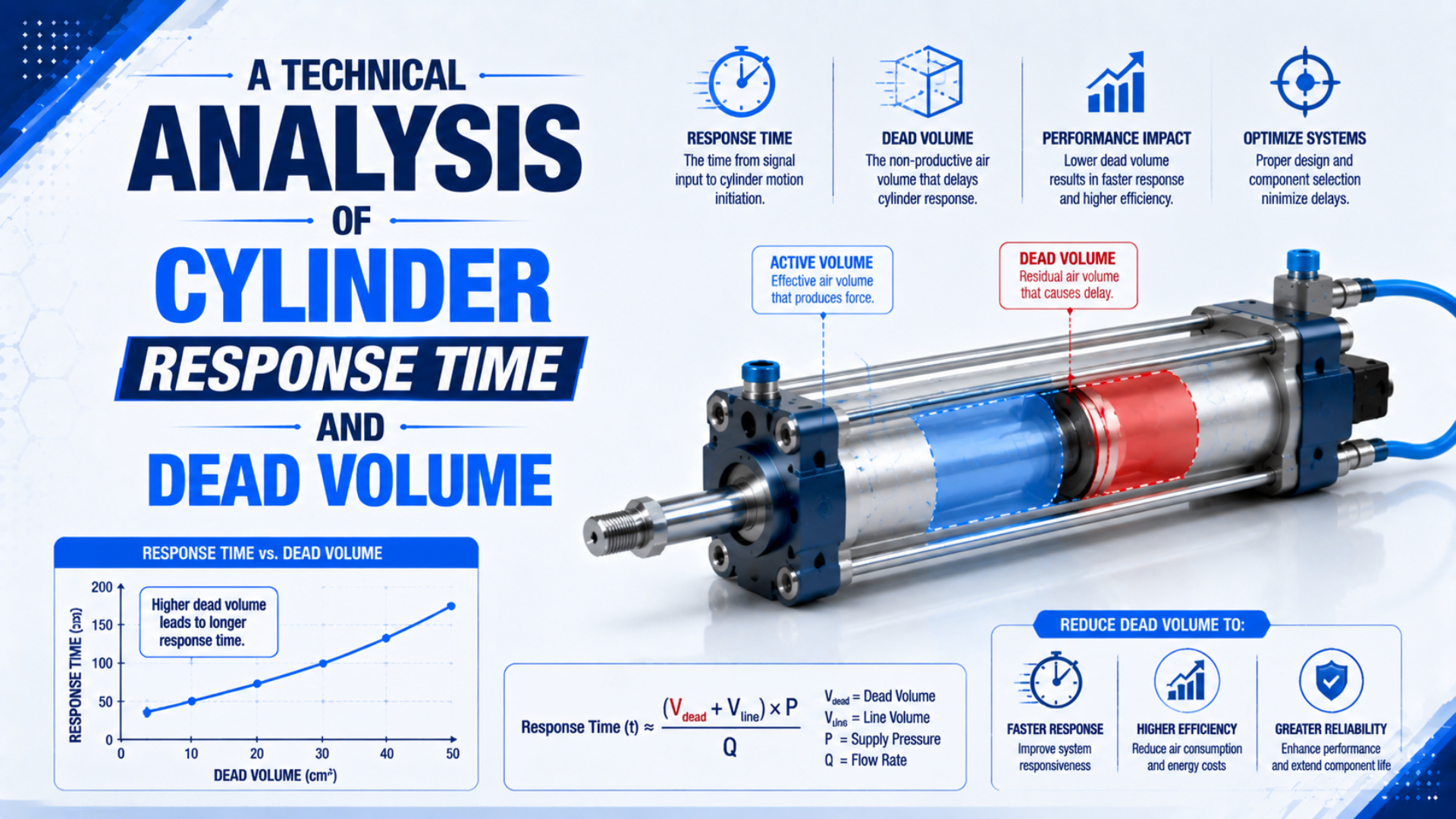
Cylinder response time is not one catalogue number. For a machine axis, it may mean command-to-first-motion delay, command-to-end-sensor time, or the complete pressure-and-position settling event. Dead volume affects each boundary differently because air must enter or leave a defined volume before pressure can overcome load and friction. Valve shift, flow capacity, exhaust back pressure, changing chamber volume, and sensor thresholds also matter.
This article focuses on command-to-first-motion delay. For the narrower valve test, use the guide to measuring pneumatic solenoid-valve response time. For travel after motion begins, use the separate pneumatic cylinder piston-velocity calculation.
Publisher and author information is available on About Us. Send technical correction requests or application questions through Contact.
Key Takeaways
- ISO 12238:2023 measures directional-valve shifting time, not complete cylinder motion.
- One metre of 6 mm ID tube contains 28.3 cm³ of physical volume.
- Pressure must reach the load-dependent breakaway threshold before motion begins.
- Smaller volume helps only when the remaining path still passes the required mass flow.
What Does Cylinder Response Time Actually Measure?
ISO 12238:2023 specifies shifting-time tests for electrically or pneumatically operated, two- or three-position directional valves. Its boundary is the valve, not the complete actuator stroke (ISO 12238, 2023). A cylinder-response specification must therefore state both the starting event and the measured finishing event.
Five useful boundaries are common in automation:
| Timing boundary | What it includes | Best use |
|---|---|---|
| Command to coil current | controller, output stage, wiring | electrical diagnosis |
| Command to valve shift | coil, armature or pilot, spool or poppet | valve comparison |
| Command to target port pressure | valve plus downstream controlled volume | pneumatic response check |
| Command to first piston motion | pressure buildup, opposing pressure, load, static friction | cylinder response diagnosis |
| Command to end sensor | all prior delays plus acceleration, travel, cushioning, and sensor | machine cycle acceptance |
Do not compare two values unless they use the same boundary. A valve can shift quickly while a remote cylinder starts late because the valve-to-cylinder volume still needs air. Conversely, a pressure transducer beside the cylinder may respond before static friction releases the piston.
Treat the event as two budgets. The pre-motion budget ends when net pneumatic force reaches the breakaway requirement. The travel budget begins when the piston moves and both chamber volumes start changing. A fixed-volume fill estimate can screen the first budget, but it cannot predict the second by itself.
Dead Volume, Controlled Volume, and Swept Volume Are Different
Parker warns that an undersized valve-to-cylinder tube throttles flow, while an oversized tube adds dead volume, air consumption, and filling time (Parker P1D guide, accessed 2026). That trade-off only makes sense when each volume is named correctly.
Cylinder clearance volume is the air space remaining in an end chamber when the piston is at its mechanical limit. It includes the end-cap pocket, port drilling, cushion passages, and any unavoidable clearance between the piston and end cap.
Controlled line volume is the tube, fitting, speed-control, manifold, and connected passage volume between the active valve seat or spool path and the cylinder port. It must be filled or exhausted during switching, but it is not always called cylinder dead volume in engineering literature.
Swept volume is the piston area multiplied by the distance travelled. It begins changing after motion starts. Extension and retraction differ because a single rod reduces the rod-side effective area.
The active volume depends on valve state and circuit layout. A speed controller attached directly to the cylinder may be inside the controlled volume. A quick-exhaust valve can move the exhaust boundary closer to the port. A center-position valve may isolate, pressurize, or exhaust the chambers differently. Trace the actual active path rather than adding every component volume indiscriminately.
For the stiffness and settling effects of trapped compressed air, use the separate analysis of air compressibility in pneumatic cylinder control.
How Do You Calculate the Volume Before the Piston Moves?
A 6 mm ID tube contains 28.27 cm³ per metre, calculated from its circular area. Parker’s tubing guidance confirms that valve-to-cylinder tube length and bore affect both flow restriction and filling time (Parker P1D guide, accessed 2026).
Tube volume follows directly from geometry:
is actual tube inside diameter and is tube length. Use consistent units. With millimetres for diameter and length, divide cubic millimetres by 1,000 to obtain cubic centimetres.
The initial controlled volume on one side is:
Include only passages connected to that chamber in the commanded valve state. Supplier drawings or measured cavity volumes are preferable to estimates. If fitting and valve internal volumes are not published, mark them as unknown instead of assigning a generic percentage.
Worked example: 6 mm ID tube, 2 m long
For a tube with 6 mm actual ID and 2 m length:
Assume the connected port, fittings, and end clearance add 10.0 cm³. The fixed pre-motion controlled volume is then 66.55 cm³.
Suppose the chamber starts at 1 bar absolute and must reach an estimated breakaway threshold of 4 bar absolute. Under a preliminary isothermal fixed-volume assumption, the equivalent free-air addition referenced to 1 bar absolute is:
This example requires about 199.7 cm³ of equivalent free air. If effective free-air flow were held at 300 L/min, or 5,000 cm³/s, the simple constant-flow screen would give about 40 ms. Real component flow changes with upstream and downstream pressure, so this is not a guaranteed response time.
The result exposes a common mistake. A source table that lists 6 mm ID tube as 2.83 cm³ per metre is off by a factor of ten. The correct value is 28.27 cm³ per metre.
Why Is There No Universal Milliseconds-per-Cubic-Centimetre Rule?
A 2026 experiment measured piston position, velocity, both chamber pressures, and friction for three pneumatic cylinders. It found that motion emerges from the coupled interaction of pressure buildup, changing chamber volume, piston area, and friction, not volume alone (Actuators, 2026).
At equal pressure thresholds and equal effective mass flow, a larger fixed volume generally takes longer to pressurize. The proportional relationship breaks when any of these conditions change:
- the valve enters a different subsonic or choked-flow region;
- the supply pressure falls during the event;
- the exhausting chamber retains back pressure;
- static friction or external load changes the breakaway threshold;
- the piston starts moving and expands the filling chamber;
- temperature changes enough to alter the pressure-mass relationship;
- a cushion, meter-out controller, or silencer becomes the dominant restriction.
ISO 6358-1 defines steady-state flow testing for pneumatic components with compressible fluids and specifically excludes cylinders that exchange energy with the fluid (ISO 6358-1, 2013, amended 2026). Use its component data to model valve and restriction flow. Do not present that steady-flow test as a complete cylinder-motion model.
For a fixed volume under an isothermal approximation, the air mass needed to rise from initial to breakaway pressure is:
is the specific gas constant and is absolute temperature. Time follows from the pressure-dependent mass-flow rate:
The function must come from valid supplier flow data or a documented compressible-flow model. ISO 6358-3 provides a system method for components and piping whose individual flow characteristics are known, covering both subsonic and choked behaviour (ISO 6358-3, confirmed 2025).
A Response-Time Model Must Include Breakaway Pressure
The 2026 three-cylinder study found that increased airflow accelerated pressure buildup during sticking and reduced the dwell required to overcome static friction, yet the resulting slip behaviour still depended on cylinder geometry and friction (Actuators, 2026). First motion therefore requires a force condition, not just a filled volume.
For extension of a horizontal, single-rod cylinder, a simplified breakaway condition is:
and are gauge pressures acting on opposite sides, is full piston area, is rod-side annular area, and the right side contains the external resisting load plus static friction. Add gravity or other forces with the correct sign for vertical and overhauling loads.
This condition explains why two identical volumes can produce different delays. A lightly loaded, well-aligned cylinder may move at a lower chamber pressure. A side-loaded or cold cylinder may need more pressure to break away. If the opposite chamber cannot exhaust, also raises the required driving pressure.
Once motion begins, the chamber volumes change with position:
is piston position measured from the retracted end and is stroke. is cap-end clearance at retraction, while is rod-end clearance at full extension. These variable volumes couple pressure, mass flow, acceleration, and friction. That is why the pre-motion 40 ms screen in the worked example must not be added blindly to a catalogue stroke time.
The best sensitivity study separates two questions: how much controlled volume must reach breakaway pressure, and how much flow the expanding chamber needs after motion starts. Reducing the first volume may improve initial response while an undersized tube still limits travel. Increasing tube ID may improve travel while its added volume delays first motion.
How Should You Measure Command-to-Motion Delay?
The 2026 experimental study sampled cylinder position, pressure, velocity, and friction at 1.16 ms intervals, showing why synchronized traces reveal more than a stopwatch (Actuators, 2026). A production test can be simpler, but every channel must share one time base and resolve the acceptance limit.
Use at least three synchronized channels:
- Command or coil voltage: establishes when the circuit was told to change.
- Cylinder-port pressure: shows how quickly the controlled volume pressurizes or exhausts.
- Position: identifies first motion and the selected travel or end-sensor event.
Add the opposite chamber pressure when exhaust back pressure may oppose the piston. Record point-of-use supply pressure during the event, not only before it. A flow trace can help, but its sensor volume and restriction must not materially change the circuit being tested.
Define first motion with a threshold larger than sensor noise, such as a specified position change from the initial value. Define pressure response as a named fraction or absolute level. Then repeat enough cycles to report minimum, average, maximum, and variation rather than one favourable trace.
Move the pressure sensor in stages when the delay location is unclear. Measure near the valve, then at the cylinder port, while keeping the remaining conditions fixed. The difference isolates line-fill and restriction effects. The later gap between port pressure and first motion belongs to load, friction, opposing pressure, and mechanics.
Which Design Changes Reduce Delay Without Creating a New Bottleneck?
Parker’s cylinder guidance states that too small a tube throttles cylinder speed, while an oversized valve-to-cylinder tube increases dead volume and filling time (Parker P1D guide, accessed 2026). The correct change reduces measured delay while preserving the mass flow required after motion starts.
| Design change | Potential benefit | Boundary to check |
|---|---|---|
| Move the directional valve closer | reduces controlled line volume | temperature, vibration, wiring, service access |
| Reduce unnecessary tube length | lowers volume and wall loss | moving-axis routing and bend radius |
| Select tube ID from flow and volume | balances restriction and fill volume | actual ID, length, both motion directions |
| Use direct-mounted flow controls | reduces remote connection volume | meter-in/meter-out direction and adjustment access |
| Add a quick-exhaust valve | shortens a selected exhaust route | noise, contamination, cushion, speed stability |
| Increase valve conductance | raises mass flow through the active path | valve shifting time, pressure ratio, exhaust data |
| Reduce cylinder bore when force permits | reduces chamber volume and flow demand | load margin, rod buckling, impact, mounting |
A quick-exhaust valve does not automatically reduce supply-side delay or air consumption. It changes the exhaust boundary for the connected chamber. On a meter-out circuit it can also remove the back pressure used to stabilize speed. Recheck cushioning and machine risk before accepting the faster motion.
Raising pressure is not the first fix. It changes breakaway force, acceleration, impact energy, stored air, leakage, and consumption. It may raise mass flow through a choked restriction, so the claim that benefits universally stop above 6 or 7 bar is incorrect. Choking depends on the component’s critical pressure ratio and upstream/downstream absolute pressures. Use the separate choked-flow cylinder-speed analysis when the pressure ratio is the suspected limit.
For tube and fitting selection after the response boundary is defined, follow the hose and fitting size guide. The chosen tube must satisfy both response-volume and working-flow checks.
What Should a Response-Time Specification Include?
ISO 12238:2023 covers valve shifting-time procedures for two- and three-position directional valves, but a complete cylinder specification must add the downstream volume, load, sensor, and motion boundary (ISO 12238, 2023). Without those conditions, two suppliers can quote different but internally valid response times.
Record these fields in an RFQ or test report:
| Field | Required detail |
|---|---|
| Start event | PLC output, driver voltage, or coil current threshold |
| Stop event | valve shift, target port pressure, first motion, or end sensor |
| Pressure threshold | absolute or gauge value, or defined percentage |
| Supply condition | minimum dynamic pressure during the test |
| Exhaust condition | valve path, silencer, quick exhaust, back pressure |
| Controlled volume | tube ID and length, fitting and port volume, valve location |
| Cylinder | bore, rod, stroke, clearance, cushion settings |
| Load | mass, direction, external force, guide friction, gravity |
| Sensors | model, location, range, accuracy, response, sample rate |
| Repetition | cycle count, minimum, mean, maximum, variation |
| Temperature | cold start, warmed machine, ambient range |
If the requirement is full stroke time rather than first motion, estimate travel separately with the Stroke Time Calculator and then validate the assembled circuit. Do not hide valve delay, line fill, travel, cushioning, and sensor time inside one unexplained allowance.
The most useful acceptance sentence is explicit: “From PLC command-on to the first 0.5 mm of extension, the cylinder shall respond within the stated limit at the documented supply pressure, load, tube configuration, temperature, and cushion setting.” Replace the example threshold with one that exceeds the actual position sensor’s noise and uncertainty.
Cylinder Response Time and Dead Volume FAQs
ISO 12238:2023 defines directional-valve shifting tests, while Parker warns that oversized valve-to-cylinder tubing adds dead volume and filling time. These answers separate valve time, pressure buildup, first motion, and complete travel rather than quote one universal millisecond value (ISO; Parker).
How much delay does one cubic centimetre of dead volume add?
There is no universal milliseconds-per-cubic-centimetre value. Delay depends on initial and target absolute pressures, pressure-dependent mass flow, opposing chamber pressure, breakaway load, friction, temperature, and whether the piston begins moving during the event. Under identical fixed-volume conditions, response time generally scales with volume, but those conditions must be stated.
Is tube volume the same as cylinder dead volume?
No. Tube volume is part of the controlled line volume between the valve and cylinder. Cylinder dead or clearance volume remains in the chamber at an end position. Both may need pressurization or exhaust, but their locations and roles differ. Keep them separate in drawings, calculations, and acceptance reports.
Does mounting the valve directly on the cylinder always improve response?
Direct mounting usually reduces valve-to-cylinder controlled volume and can shorten pressure buildup. It does not guarantee faster complete travel if valve conductance, exhaust capacity, load, friction, or cushioning is limiting. Check environmental exposure, vibration, wiring, service access, moving mass, and the measured supply and exhaust paths before changing the architecture.
Can a quick-exhaust valve eliminate dead-volume delay?
No. A quick-exhaust valve shortens the selected chamber’s exhaust route; it does not remove cylinder clearance or supply-side controlled volume. It may increase speed, noise, and end impact while reducing stabilizing meter-out back pressure. Confirm motion direction, cushion capacity, contamination protection, and machine safety before accepting the change.
What signals should be recorded during a cylinder response test?
Record the electrical command, driving-side cylinder-port pressure, and position on one synchronized time base. Add the opposing chamber pressure when exhaust back pressure is possible, and record dynamic supply pressure during the event. State the sensor locations, sample rate, thresholds, load, tube configuration, temperature, and repeated-cycle statistics.
Sources and technical references
- ISO 12238:2023, Pneumatic fluid power: Directional control valves: Measurement of shifting time, accessed 2026-07-19.
- ISO 6358-1:2013, flow-rate characteristics of pneumatic components, including 2026 measurement-uncertainty amendment, accessed 2026-07-19.
- ISO 6358-3:2014, system flow-rate calculation method, confirmed 2025, accessed 2026-07-19.
- Parker P1D pneumatic cylinder and tubing selection guide, accessed 2026-07-19.
- Experimental and System-Level Simulation Study of Stick–Slip Characteristics in Pneumatic Cylinders, 2026, accessed 2026-07-19.