

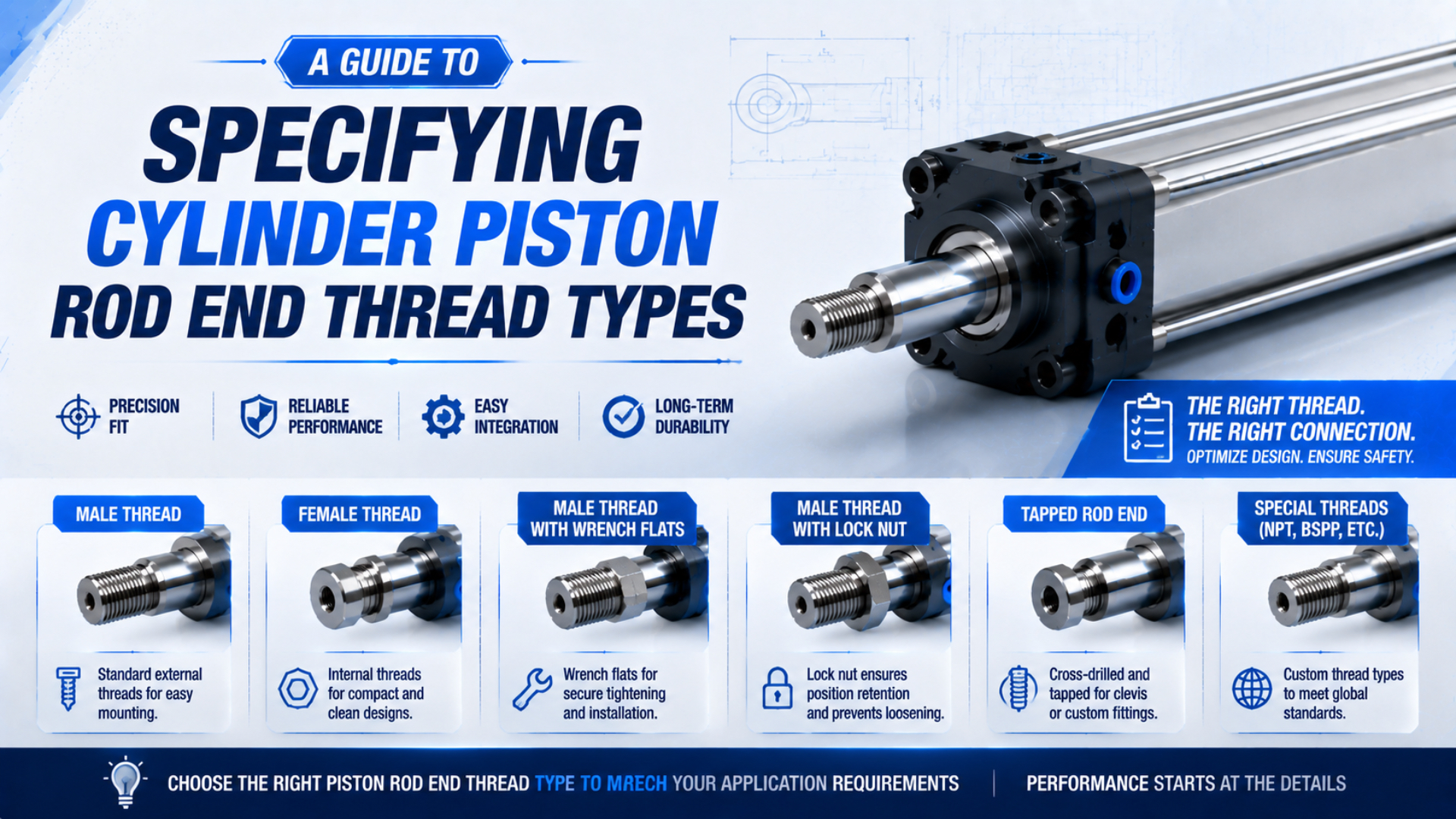
A complete cylinder piston rod end thread specification identifies the thread system, nominal size, pitch or threads per inch, thread gender, tolerance class, usable length, hand, shoulder geometry, material condition, and mating accessory. A callout such as “M16” or “3/8 UNF” leaves several of those decisions unresolved.
Start with the exact cylinder model and configured drawing. Then verify the mating clevis, rod eye, coupling, or machine part against the same callout. Don’t infer the rod end from the air-port thread, cylinder bore, country of installation, or an ISO compliance label.
Key Takeaways
- ASME Unified threads use six ordinary class designations: 1A, 2A, 3A, 1B, 2B, and 3B.
- ISO 15552 covers 32-320 mm cylinders, but the configured rod end still needs drawing-level verification.
- A reliable RFQ records ten interface fields, not only diameter and pitch.
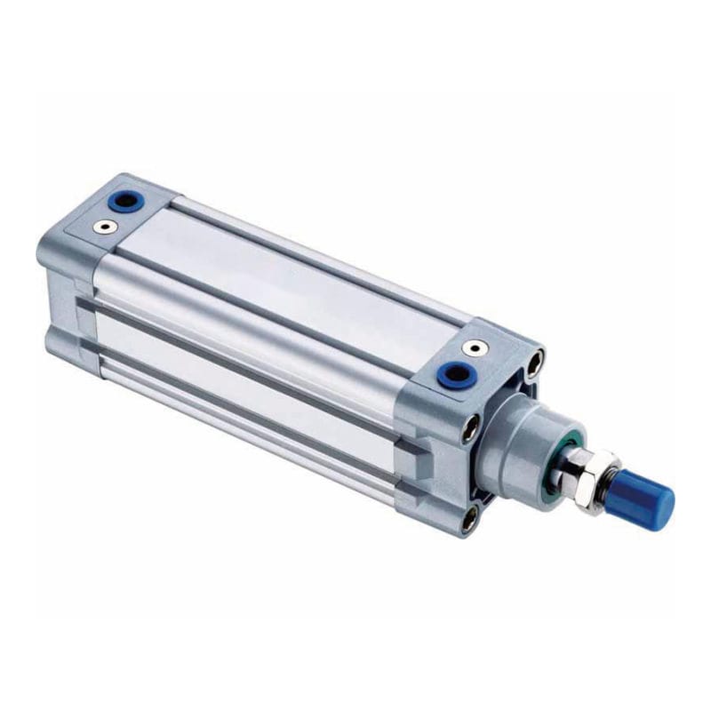
The protective cap identifies the rod-end location, but the thread itself must be confirmed from the configured drawing rather than from a product photograph.
This guide covers the mechanical thread at the end of a piston rod. Pneumatic port threads are a different interface. If the part in question carries compressed air, use the separate guide to cylinder port thread types instead.
In this guide
- What must a complete rod-end thread callout contain?
- How do metric and Unified thread callouts differ?
- Should you choose a coarse or fine pitch?
- Cylinder and accessory standards control different layers
- How should load, engagement, and locking be checked?
- How do you write a procurement-ready specification?
- Freeze the approved interface before repeat orders
- Cylinder Rod End Thread FAQs
What Must a Complete Rod-End Thread Callout Contain?
Parker’s pneumatic actuator catalog defines separate symbols for thread diameter and pitch, thread length, male rod-end length, and female-thread depth, and it offers five standard rod-end styles. That catalog structure shows why a nominal thread name alone cannot define the physical interface (Parker Catalog 0900P, accessed 2026).
Record these ten fields before releasing a drawing or RFQ:
A rod-end thread callout is the controlled set of dimensions and requirements that defines how the piston rod connects to its mating accessory. It is broader than the nominal thread designation because seating, usable length, locking, and accessory geometry also affect whether the assembly fits and carries load correctly.
| Field | Example | Why it matters |
|---|---|---|
| Thread system | ISO metric or Unified inch | Establishes the governing profile and designation rules |
| Nominal size | M16 or 5/8 in | Defines the nominal diameter family |
| Pitch or TPI | 1.5 mm or 18 TPI | Prevents a same-diameter, wrong-pitch mismatch |
| Gender | External or internal | Determines whether the rod carries a stud or tapped end |
| Tolerance class | 6g, 6H, 2A, or 2B | Defines the dimensional tolerance and allowance system |
| Hand | Right-hand unless stated otherwise | Prevents unintended loosening logic or assembly failure |
| Usable engagement | Dimensioned length or depth | Excludes incomplete runout and bottom clearance |
| Shoulder and runout | Diameter, relief, and corner clearance | Lets the mating part seat without binding on the first incomplete thread |
| Locking features | Jam nut, prevailing device, or approved adhesive | Defines how adjustment is retained |
| Material and surface | Rod grade, coating, mating material, lubrication | Affects wear, corrosion, galling, friction, and allowable thread stress |
The mating component belongs in the same review. A clevis can have the correct nominal thread and still bottom against a shoulder, run out of internal depth, or lose clamp load because its jam nut cannot seat.
Treat the rod end as a three-surface interface: the helical thread transmits axial load, the shoulder or jam nut establishes the seated condition, and the accessory geometry directs the load into the machine. Checking only the first surface misses two common causes of field incompatibility.
Male and Female Rod Ends
An external male thread is easy to inspect with a ring gauge and accepts common clevises, rod eyes, and couplings. It also exposes the thread during handling. A female rod end protects the thread inside the rod but requires enough rod diameter, thread depth, bottom clearance, and wall thickness for the intended load.
Neither gender is universally stronger. Compare the complete supplier rating and drawing. Parker catalogs both female and male piston-rod thread configurations, which confirms that gender is a configured cylinder option rather than a regional assumption (Parker P1P catalog, accessed 2026).
Rod-End Threads Are Not Port Threads
BSPT, NPT, and parallel G pipe threads belong to fluid connections and sealing systems. They shouldn’t be placed in a standard rod-end attachment table unless a controlled special drawing deliberately uses one as a mechanical interface. The NPT standard guide explains why tapered pipe threads require separate sealing and engagement rules.
Acme and metric trapezoidal threads are power-screw forms. They can appear in engineered mechanisms, but they aren’t ordinary pneumatic cylinder rod-end choices for “precision positioning.” A cylinder’s rod-end thread attaches hardware; it doesn’t turn the pneumatic actuator into a lead screw.
How Do Metric and Unified Thread Callouts Differ?
ISO 965-6:2025 lists ten recommended metric tolerance classes, while ordinary Unified threads use the six familiar A/B class designations in ASME B1.1. Lowercase metric letters generally identify external-thread tolerance positions, uppercase letters identify internal threads, and Unified A/B serves the same external/internal distinction (ISO 965-6; ASME B1.1).
Reading an ISO Metric Callout
Consider this external-thread example:
M16 x 1.5 - 6g, external RH, 24 mm usable threadMidentifies the ISO metric thread system.16is the nominal diameter in millimetres.1.5is the pitch in millimetres.6gis the external-thread tolerance class.RHconfirms a right-hand thread.24 mm usable threadis a controlled length, not an assumption from nominal size.
ISO 261 specifies the general plan for ISO metric M threads and directs tolerance selection to ISO 965-1 (ISO 261:1998, confirmed 2024; ISO 965-1:2026). If the pitch is omitted from a drawing, the standard coarse pitch may be implied, but stating the pitch removes ambiguity in international purchasing.
A common mating internal thread might use 6H, but don’t automatically add that value to every cylinder specification. The drawing owner must choose and verify the actual fit, coating allowance, inspection method, and mating part.
Reading a Unified Inch Callout
Consider this external-thread example:
3/8-24 UNF-2A, external RH, 0.75 in usable thread3/8is nominal diameter in inches.24is threads per inch.UNFidentifies the Unified Fine series.2Aidentifies a Class 2 external thread.- A mating internal thread would use a B designation, commonly
2Bwhen that fit is specified.
Class 1, 2, and 3 describe progressively tighter tolerance classes. They are not material grades, load ratings, or automatic vibration ratings. Current ASME B1.1 does not provide ordinary 4A/4B classes, so those designations should not appear in a standard procurement table.
Thread tolerance class is the standardized combination of tolerance grade and position, or allowance, applied to thread dimensions. It controls permissible size variation and mating fit. It doesn’t by itself define tensile strength, stripping strength, fatigue life, vibration resistance, or the suitability of a locking method.
| Thread system | External example | Internal mate example | Unit used for pitch |
|---|---|---|---|
| ISO metric | M16 x 1.5 - 6g | M16 x 1.5 - 6H | Millimetres per thread |
| Unified coarse | 3/8-16 UNC-2A | 3/8-16 UNC-2B | Threads per inch |
| Unified fine | 3/8-24 UNF-2A | 3/8-24 UNF-2B | Threads per inch |
Should You Choose a Coarse or Fine Pitch?
Festo’s ISO 15552 DSBC data assigns M10x1.25, M12x1.25, and M16x1.5 male rod threads across 32, 40, 50, and 63 mm bores. Those values demonstrate that actual cylinder families use manufacturer-controlled pitch selections, not a universal rule that maps “coarse” to heavy duty and “fine” to precision (Festo DSBC).
Use the cylinder maker’s standard rod-end option when it matches the accessory and load. Depart from it only with an engineering reason and a controlled special drawing.
| Selection factor | Coarser pitch tendency | Finer pitch tendency | What must still be verified |
|---|---|---|---|
| Assembly speed | Fewer turns for the same travel | More turns for the same travel | Required adjustment procedure |
| Damage tolerance | Deeper thread form can be more tolerant of dirt and handling | Shallower pitch can be more sensitive to damage | Material, coating, cleanliness |
| Tensile stress area | Usually lower at the same nominal diameter | Usually higher at the same nominal diameter | Actual external-thread tensile limit |
| Internal-thread stripping | Can benefit in soft mating materials, depending on geometry | More engaged threads per unit length | Internal material and usable depth |
| Adjustment resolution | More axial movement per turn | Less axial movement per turn | Jam nut and final locking method |
This table describes tendencies, not ratings. Fine pitch doesn’t create pneumatic positioning accuracy, and coarse pitch doesn’t guarantee vibration resistance. Preload, seating, transverse load, cyclic force, locking method, damage, and installation quality control the joint behavior.
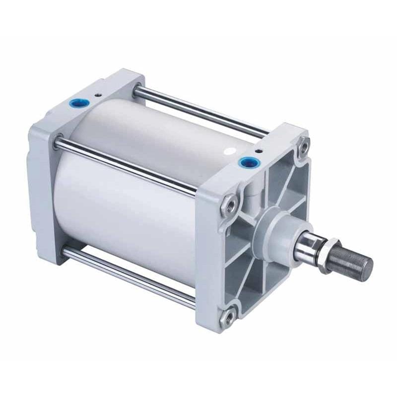
An exposed external thread makes diameter, pitch, usable length, runout, shoulder, and jam-nut clearance available for direct inspection.
Cylinder and Accessory Standards Control Different Layers
ISO 15552:2018 covers detachable-mount pneumatic cylinders from 32 to 320 mm bore at a maximum rated pressure of 1,000 kPa, or 10 bar. Its scope is basic, mounting, and accessory dimensions for interchangeability, not a promise that every supplier option shares one rod-end callout (ISO 15552, confirmed 2025).
Use three evidence layers:
- Cylinder standard: establishes the applicable dimensional family and scope.
- Supplier configuration: identifies the exact rod end, port, rod material, cushioning, sensing, and order-code options.
- Machine interface drawing: controls the mating accessory, installed length, alignment, clearance, and acceptance criteria.
The ISO 15552 cylinder interchangeability workflow applies those layers to a complete replacement. For a rod-end-only review, keep the same discipline but narrow the comparison to the load path and accessory envelope.
ISO 8140:2018 separately specifies interchangeable mounting dimensions for threaded rod-end clevises used with 10 bar pneumatic-cylinder series. Its design basis uses the maximum forces resulting from cylinder bore and pressure under ISO 6432, ISO 15552, and ISO 21287 (ISO 8140, confirmed 2024).
That division of responsibility matters. The cylinder standard, accessory standard, supplier drawing, and machine drawing can all be correct while controlling different dimensions. A purchase specification should identify which document owns each interface instead of asking one standard to prove the whole assembly.
Standards That Do Not Define the Rod-End Callout
ISO 9001 addresses a quality-management system. CE and UL requirements depend on the product, machinery, market, and applicable conformity route. None of those labels substitutes for the rod thread’s diameter, pitch, gender, tolerance class, length, shoulder, or mating accessory.
Regional preference is also weak evidence. Metric threads are common globally, but North American equipment can use metric cylinders and European machinery can contain Unified special interfaces. Read the installed drawing and part number.
How Should Load, Engagement, and Locking Be Checked?
NASA RP-1228 shows calculated torque coefficients changing from 0.074 to 0.250 as the assumed friction coefficient changes from 0.05 to 0.20. That sensitivity helps explain why thread class or a generic tightening torque cannot establish joint strength without material, lubrication, geometry, and load information (NASA Fastener Design Manual).
Begin with the maximum axial force the cylinder can transmit, including pressure variation and the actual operating state. The ideal pneumatic force relationship is:
Here, is theoretical axial force in newtons, is effective pressure in pascals, and is the pressurized piston area in square metres. The equation assumes uniform pressure and excludes friction, back pressure, acceleration, shock, side loading, and safety requirements. It establishes a load input, not allowable thread capacity.
For force and unit-conversion details, use the pneumatic cylinder rod-area guide before reviewing the mechanical joint.
Check More Than Tensile Stress
The engineering review should address:
- tensile capacity of the external threaded section
- stripping capacity of both external and internal threads
- effective engagement after chamfer, runout, and bottom clearance are excluded
- fatigue from repeated axial load and impact
- bending caused by misalignment or an unsupported accessory
- shoulder bearing and jam-nut seating
- corrosion, coating buildup, lubrication, wear, and stainless-steel galling risk
- loosening control and the approved assembly procedure
There is no universal 1.0d or 1.5d engagement rule that guarantees full strength for every material pair. A steel male thread in an aluminium clevis does not have the same stripping limit as a steel-on-steel joint. Use the applicable thread shear-area method, actual material allowables, supplier limits, and verified usable depth.
Effective thread engagement is the axial length over which complete external and internal thread forms can carry load together. It excludes lead-in chamfers, incomplete runout, damaged threads, and unused space at the bottom of a blind hole. Nominal tapped depth and effective engagement are therefore not interchangeable dimensions.
Likewise, don’t assign 3:1, 5:1, or 10:1 merely from a broad industry label. The required design margin comes from the machine risk assessment, governing safety standard, load uncertainty, consequence of failure, and approved company design rules.
Control Side Load and Seating
Parker warns that piston rods are not normally designed to absorb bending moments or loads perpendicular to rod motion, and that an external stop can impose bending and impact on the rod (Parker Catalog 0900P). A correct thread can’t compensate for a misaligned linkage.
Use a clevis or spherical rod eye when the mechanism needs articulation, then confirm its angular range and installed geometry. Tighten a jam nut against the intended flat shoulder, not against incomplete thread runout. If the accessory must remain adjustable, define how final orientation and locking will be inspected.
A thread gauge answers “Was the thread manufactured within its specified limits?” It doesn’t answer “Will this accessory seat, align, lock, and survive the machine load?” Inspection plans need both conformance checks and an interface-level assembly check.
How Do You Write a Procurement-Ready Specification?
Parker’s catalog asks buyers to identify thread diameter and pitch, thread length, male or female rod-end dimensions, and a dimensioned sketch for specials. Turning those controls into one RFQ line prevents several rounds of clarification and makes the received part inspectable against the released requirement (Parker Catalog 0900P).
Use this workflow:
- Record the installed cylinder manufacturer, complete part number, revision, bore, stroke, and rod-end option.
- Obtain the current configured drawing. Don’t copy a generic family table when option suffixes change the rod end.
- Identify the mating part number and its controlled drawing.
- Verify thread system, nominal size, pitch/TPI, gender, tolerance class, and hand.
- Compare usable thread length or depth, shoulder diameter, relief, runout, chamfer, and bottom clearance.
- Confirm jam nut, clevis, rod eye, coupling, spacer, or spherical bearing dimensions.
- Review axial force, side load, fatigue, environment, locking method, and assembly instructions.
- Define inspection evidence, such as thread gauges, dimensional report, material certificate, coating record, and first-article assembly.
- Freeze the approved supplier drawing and machine-interface revision.
- Test the first article at the machine before releasing unrestricted repeat orders.
Example RFQ Callout
Piston rod end:
M16 x 1.5 - 6g external, right-hand
24 mm minimum usable full-form thread
Shoulder diameter and runout per attached drawing DR-1042 Rev C
Supplied with matching M16 x 1.5 jam nut
Rod material and surface treatment per cylinder supplier specification
Mating clevis: part CL-216 Rev B
First article: thread gauge report plus verified clevis seating and alignment
No substitution of pitch, thread gender, or rod-end geometry without written approval
For cross-supplier work, include both the original and proposed configured drawings. A statement such as “same ISO cylinder” isn’t enough. The review should show that the rod end, accessory, mounting envelope, ports, sensors, cushioning, and operating limits remain compatible.
Freeze the Approved Interface Before Repeat Orders
ISO 15552 spans cylinder bores from 32 to 320 mm, while Parker documents five standard rod-end styles plus special configurations. That range of standardized envelopes and supplier options makes revision control essential: the accepted part number, configured drawing, accessory, inspection record, and machine trial must stay linked after approval (ISO 15552; Parker Catalog 0900P).
Save the accepted supplier drawing and machine-interface drawing with their revision identifiers. Record any approved deviation, first-article measurements, thread-gauge result, and mating-accessory check. Purchasing should reorder the exact released configuration, not a family name reconstructed from an email description.
If a supplier changes the rod material, coating, tolerance class, thread length, shoulder, jam nut, or option suffix, reopen the interface review. A same-size thread can still change seating, friction, corrosion behavior, or effective engagement. Configuration control is what turns a successful first article into a repeatable replacement.
Cylinder Rod End Thread FAQs
ASME B1.1 uses six ordinary A/B class designations, while ISO 965-6:2025 lists ten recommended metric tolerance classes. Most rod-end questions become easier once the thread system, external/internal designation, configured drawing, and mating accessory are identified before strength or locking assumptions are made (ASME B1.1; ISO 965-6).
Can a metric rod end be used in an inch-based machine?
Yes, if the mating interface is intentionally redesigned or a rated adapter is approved. Don’t force a near-fitting inch accessory onto a metric thread. Record both sides of the conversion, check installed length and articulation, and ensure the adapter doesn’t introduce unsupported bending, reduced engagement, or an unapproved failure point.
Is 6g the same kind of designation as 2A?
Both describe external-thread tolerance classes, but they belong to different standards and aren’t direct equivalents. 6g is an ISO metric designation; 2A is a Unified inch designation. Specify the complete thread system and mating internal thread, then inspect each part with the gauges and limits applicable to that system.
Does a tighter thread class make the rod end stronger?
Not automatically. A tighter class changes tolerance and fit, not the rod material, effective tensile area, internal-thread shear area, engagement, or fatigue loading. Strength must be checked from the complete joint. Selecting Class 3 solely for vibration or “maximum strength” can add manufacturing and assembly difficulty without solving the actual load problem.
How much thread engagement is enough?
There is no universal multiple of nominal diameter that guarantees full strength. Required engagement depends on external and internal materials, thread geometry, tolerance, effective full-form depth, loading, and the design margin. Use a recognized thread-strength method plus supplier limits, then confirm that chamfers, runout, and bottom clearance aren’t counted as usable engagement.
What information is needed for a custom rod end?
Provide the complete cylinder model, bore, stroke, rod diameter, thread drawing, gender, hand, pitch, tolerance class, usable length, shoulder and relief geometry, material and coating, mating accessory, axial and transverse loads, environment, locking method, and inspection criteria. A dimensioned drawing is safer than a text-only request for any nonstandard geometry.
Sources and technical references
- ASME B1.1-2024, Unified Inch Screw Threads
- ISO 261:1998, ISO General Purpose Metric Screw Threads
- ISO 965-1:2026, Metric Screw Thread Tolerance Principles
- ISO 965-6:2025, Metric Internal and External Thread Limits
- ISO 15552:2018, Pneumatic Cylinder Basic, Mounting and Accessory Dimensions
- ISO 8140:2018, Rod-End Clevis Mounting Dimensions
- NASA RP-1228, Fastener Design Manual
- Parker Catalog 0900P, Pneumatic Actuator Products
- Festo DSBC ISO 15552 Cylinder Technical Data