

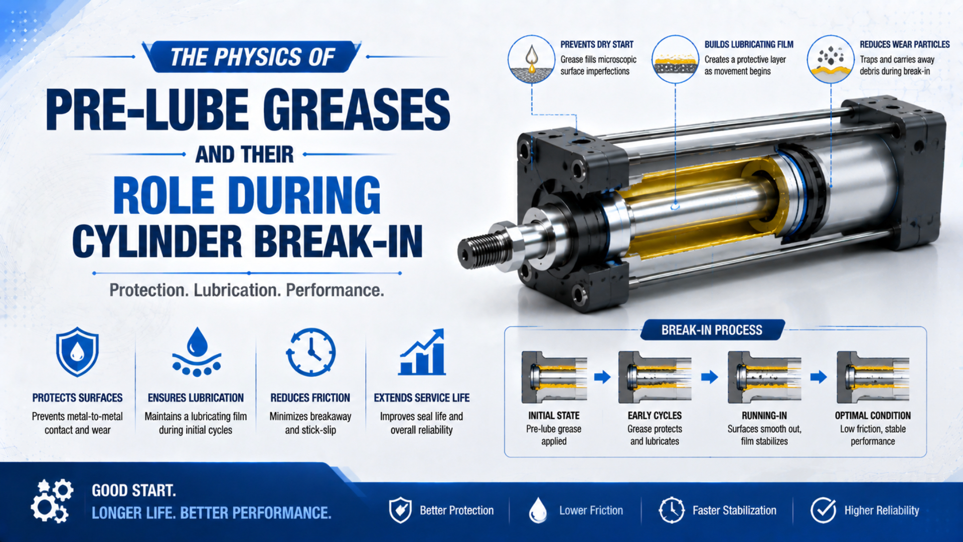
Pre-lube grease is the compatible lubricant applied to pneumatic-cylinder seals and sliding surfaces during manufacture or an approved rebuild. It reduces installation drag, protects seal lips as they enter the bore, and establishes the initial lubricant film. Parker reports that suitable assembly lubrication can reduce surface friction between an O-ring and its mating surface by up to 60% during installation (Parker O-Ring Handbook, 2026).
That 60% figure doesn’t mean a lubricated cylinder produces 60% more force or lasts 60% longer. It describes one supplier’s seal-installation result. The operating effect depends on the exact seal compound, grease, geometry, pressure, temperature, speed, dwell, air quality, and application quantity. Modern factory-lubricated cylinders also don’t need a universal timed conditioning program unless their manufacturer specifies one.
That boundary matters during every rebuild.
Key Takeaways
- Suitable assembly lubricant can reduce seal installation friction by up to 60% (Parker, 2026).
- Pre-lube, lifetime grease, airline oil, and service grease are different instructions.
- Grease type and quantity must follow the exact cylinder or seal-kit documentation.
- Initial commissioning verifies function; it isn’t a universal wear-in schedule.
The useful engineering model is not “grease plus break-in.” It is lubricant, location, quantity, material compatibility, and verification. If any one of those five items is unknown, adding more grease is not a controlled correction.
What Does Pre-Lube Grease Actually Do in a Pneumatic Cylinder?
Parker’s 2026 handbook explicitly attributes an installation-friction reduction of up to 60% to suitable O-ring lubrication. The practical result is lower insertion force and less risk of twisting, shearing, cutting, or displacing a seal as a piston or rod assembly crosses a chamfer and enters its running surface (Parker, 2026).
Once assembled, a small amount of oil from the grease can support sliding at the interface between a polymer seal lip and its counterface. Depending on speed, pressure, dwell, surface finish, and lubricant supply, the contact can move between boundary and mixed-lubrication behavior. Those regimes aren’t fixed film-thickness bands that apply to every cylinder.
Pre-lube grease is an assembly and initial-operation control, not a substitute for cylinder design. Parker links suitable lubricant to easier seal seating and lower insertion force, while Festo’s repair guidance links the applied film to specific surfaces and reservoirs. Together, those instructions support a narrow conclusion: use the approved lubricant to prevent dry assembly and protect the sealing edge while distributing a controlled film during initial strokes. They establish no universal friction coefficient or film thickness. They also don’t support a service-life multiplier. Pressure and seal interference remain separate variables. So do surface finish and side load. Temperature, contamination and dwell also matter. If a new or rebuilt cylinder binds or starts inconsistently, preserve the evidence. Inspect those variables before treating additional grease as the remedy (Parker, 2026; Festo, 2026).
Pre-lube can perform four defensible jobs:
- Ease installation. Reduce dry drag during insertion.
- Reduce initial dry contact. A compatible film is present before compressed air has cycled the actuator.
- Supply designed lubricant reservoirs. Some profiles retain grease between sealing lips or inside ring volumes so oil remains available at the intended sliding interface instead of collecting elsewhere in the cylinder.
- Stabilize early motion. Full strokes distribute lubricant over the running surfaces.
What doesn’t follow? Pre-lube does not prove zero wear or prevent every scoring failure. It cannot correct a damaged bore or compensate for side load. It also isn’t evidence that a cylinder requires deliberate metal micro-wear. For definitions of piston and rod seals plus wipers and guide rings, use the industrial cylinder seal guide.
Four Lubrication Contexts That Should Not Be Confused
Three manufacturer sources reviewed in 2026 describe at least four distinct lubrication contexts: assembly lubricant; factory lifetime grease; external airline oil; and grease supplied for an approved repair. Festo calls specific cylinders “lubricated for life” (Festo, 2026). SMC includes model-linked grease packs with selected seal kits (SMC, 2026).
One label can’t replace four instructions.
The distinction matters most with a non-lube cylinder. “Non-lube” normally means that the actuator doesn’t require oil in its compressed-air supply. It does not mean the unit contains no grease. The non-lube cylinder guide explains why that difference matters in contamination-sensitive service.
Assembly pre-lube is lubricant applied while seals and sliding parts are installed. Lifetime lubrication means the manufacturer intends the original film or reservoir to support the stated service interval without routine airline oil. External airline oil is lubricant metered into the compressed-air supply. Service grease is the approved product used during a permitted repair.
Some manufacturers also warn that once airline lubrication is introduced, it must be continued because the supplied oil can displace the original lubricant. Check the exact model manual before fitting, removing, or adjusting an oil-mist lubricator. A maintenance habit from one product family can be wrong for another.
How Should Grease Be Selected for Seals and Sliding Parts?
Parker lists six distinct functional requirements for seal lubricant: it must avoid elastomer swelling or shrinkage, remain usable across temperature, resist component separation, adhere to the interface, match the working medium, and avoid blocking system filters (Parker O-Ring Handbook, 2026).
Start with the cylinder model, service kit, and approved lubricant part number. Then verify the entire contact set, not only the piston seal. Grease may touch rod and piston seals, O-rings, wear bands, bushings, tube coatings, plastics, thread-locking residue, compressed air, condensate, process chemicals, and cleaning agents.
Our team analyzed the six cited sources and found that lubricant approval consistently depends on the full contact system, not a generic grease family. A mineral-oil product can be suitable for one seal and unsuitable for EPDM or IIR; a silicone product can solve a compatibility problem yet offer different lubrication and corrosion behavior. Temperature ratings also belong to the named product, not to every grease sharing its base oil. Before approving a substitute, identify the seal compound; plastics; metal or coating; compressed-air contaminants; cleaning agents; process medium; filtration; temperature; pressure; speed; and dwell. Then obtain written approval or test the actual combination. This approach prevents a common documentation error: recording “synthetic grease” or “silicone grease” while omitting the compound code and application location. Product designation must remain part of the record (Parker, 2026).
| Selection question | Why it changes the answer | Evidence to request |
|---|---|---|
| What is the exact seal compound? | NBR, EPDM, FKM, silicone, polyurethane, and PTFE-based materials respond differently to oils and additives | OEM compound code or approved compatibility table |
| What are the base oil and thickener? | They affect low-temperature motion, oil release, retention, and grease-mixing behavior | Lubricant technical data sheet and manufacturer approval |
| Which additives are present? | Additives can change elastomer compatibility and deposit formation | Full product designation and compatibility statement |
| What medium reaches the seal? | Compressed air may carry oil, water, cleaner residue, or process vapor | Air treatment specification and chemical list |
| What are the real temperature and duty? | Interface temperature can differ from ambient temperature; speed and dwell change friction behavior | Measured operating range, speed, dwell, cycle rate, and pressure |
| Are filters or small passages present? | Separated oil, solids, or excess grease can obstruct flow paths | Filtration rating and product-specific lubricant guidance |
Grease compatibility is a property of a specific mixture in a specific assembly. A generic statement such as “silicone is compatible with rubber” isn’t an engineering approval. Parker says its mineral-oil-based O-Lube is not recommended for IIR or EPDM. Its silicone-based product has a different application envelope. Keep product name linked to seal compound and service conditions.
Don’t mix greases casually. SKF notes that incompatible mixtures can soften; harden; or leak. Reliable confirmation requires a test of the two specific greases. Even a compatibility table doesn’t prove that a changing mixture will retain the required performance (SKF Bearing Installation, 2026).
How Much Grease Should Be Applied During Assembly?
Festo’s DZF/DZH repair guide defines three different application conditions: an extremely thin film; a thin film; and a grease reservoir. In that product-specific procedure selected seal reservoirs are filled two-thirds while other surfaces receive only a thin coat (Festo DZF/DZH Repair Guide, 2026).
That example shows why a universal 0.1 to 0.3 mm grease thickness is unsafe. The correct amount depends on the component and the way its seal lips or grooves were designed to retain lubricant. One repair manual may describe appearance, another specifies mass, and a sealed OEM kit supplies the required amount.
A defensible rebuild sequence is:
- Identify the actuator. Record its complete model code and variant.
- Obtain the service procedure. Confirm that field repair is permitted, then identify the approved wear-parts kit, grease part number, and model revision.
- Make the machine safe. Vent both chambers and support every load that could move.
- Inspect before cleaning. Photograph seal orientation and grease distribution; retain evidence of scoring, deposits, one-sided wear, or contamination before solvents and wiping change the surfaces.
- Clean as specified. Remove old grease and particles without damaging the bore or seals.
- Protect the new seal. Cover threads and sharp edges with the approved sleeve or fitting aid, inspect the lead-in, and verify lip direction before insertion.
- Apply grease by location. Use the specified film, reservoir, measured mass, or supplied kit amount.
- Distribute and remove excess. Follow the documented stroke or wipe sequence so lubricant reaches the complete running surface without remaining in uncontrolled lumps near ports, grooves, or end caps.
- Run the functional test. Check full stroke, leakage, speed, cushioning, sensors, and noise.
Too little grease can leave a dry interface or increase installation damage. Too much can raise starting resistance, migrate into the air path, trap contamination, or interfere with small passages. If the specified amount is unavailable, stop and request the series procedure rather than estimating by appearance.
Is a Timed Cylinder Break-in Period Necessary?
The Festo repair instruction calls for several full-stroke movements to distribute its lifetime lubricant, but it gives no timed, derated run. Its repaired cylinder proceeds to a functional test and commissioning under the operating instructions (Festo DZF/DZH Repair Guide, 2026).
For modern pneumatic cylinders, “break-in” is best treated as initial functional verification unless the exact manufacturer prescribes a conditioning schedule. The first strokes can distribute grease and let seals settle into their working position. They don’t justify one automatic load, speed, or cycle-count recipe.
We found no cited manufacturer instruction supporting one timed, derated break-in schedule for all pneumatic cylinders. The available service evidence instead supports a defined commissioning check: distribute lubricant as instructed; move through the full stroke; remove excess where required; then verify the rebuilt actuator against its operating instructions. This distinction matters because a slow or jerky first stroke can come from several independent mechanisms. Seal interference and grease viscosity affect friction. Trapped back pressure or a restricted exhaust can produce the same symptom. So can guide binding and side load. Incorrect assembly, cold temperature or a damaged surface also deserve inspection. Record pressure at both ports. Add the load and orientation as well as speed, dwell and temperature. Without those conditions, a “break-in improvement” cannot separate lubricant distribution from a changing pneumatic or mechanical load (Festo, 2026).
What should be checked instead?
- Confirm smooth travel through the full stroke.
- If starting force or speed is abnormal, measure pressure at both cylinder ports and record the exact point where motion begins.
- Perform the approved leakage checks.
- Verify cushion adjustment, end impact, sensor operation, mounting, and load alignment before increasing speed.
- When stick-slip is suspected, compare first movement after a defined dwell with continuous motion and keep pressure, load, temperature, and valve settings unchanged.
- Record pressure, load, speed, orientation, temperature, and air condition.
High initial pressure is not automatically a lubrication fault. Seal interference and pressure energization affect first movement. Dwell, side load and misalignment do too. Check the rod, guides and grease temperature before ignoring exhaust restriction or valve behavior. The breakaway-force guide separates starting force from running force, while the piston-seal design guide explains the role of lip geometry and compound choice.
What Problems Point to Lubrication or Assembly Error?
Parker recommends a 15 to 20-degree lead-in chamfer plus clean assembly, fitting aids and grease to prevent O-ring fitting errors. The same handbook identifies twisting; shearing; cutting; contamination; and assembly without lubrication as mechanisms that can damage seals (Parker O-Ring Handbook, 2026).
| Observation | Possible lubrication or assembly mechanism | What to verify before adding grease |
|---|---|---|
| Leakage immediately after rebuild | Cut or twisted lip, wrong orientation, debris, damaged groove, wrong seal | Part number, lip direction, fitting tool, bore and groove condition |
| High breakaway after dwell | Grease too stiff, excessive quantity, seal swell, high interference, side load | Temperature, dwell, both port pressures, seal compound, alignment |
| Uneven or jerky stroke | Stick-slip, restricted exhaust, guide binding, uneven film, valve instability | Speed controls, valve flow, load path, bore condition, lubrication instruction |
| Grease at exhaust or ports | Excess application, oil separation, wrong location, airline lubrication | Service procedure, grease quantity, lubricator setting, filter condition |
| Seal softening or dimensional change | Chemical incompatibility with base oil, additives, cleaner, or process medium | Material code, lubricant identity, cleaners, condensate, process exposure |
| Repeated one-sided wear | Misalignment, side load, worn guide, distorted mounting | Rod straightness, carriage or guide play, mounting flatness, external load |
Adding grease before diagnosis can erase evidence and hide the original mechanism. Record where the lubricant and wear were found. Then separate a dry interface from geometry or contamination. Flow-control and seal-selection problems require their own checks. The pneumatic actuator maintenance checklist provides a broader isolation and inspection sequence.
Preserve the evidence before changing anything.
What Changes for Food, Cleanroom, or Special-Media Service?
NSF distinguishes H1 lubricants for incidental food contact from H2 industrial lubricants with no food-contact allowance, while ISO 21469 addresses hygiene requirements for formulation, manufacture, and use. Neither designation proves compatibility with a cylinder’s seals or suitability for direct food contact (NSF, 2026).
For food machinery, identify whether lubricant could reach exposed product, packaging, or a product-contact surface. Then verify the current NSF registration or ISO 21469 certification for the exact lubricant name. Use only the minimum quantity needed for the technical function and retain the listing, lot, and application record required by the site’s food-safety program.
Cleanroom selection asks different questions. A non-lube actuator may eliminate airline oil, yet it can still contain grease, polymer seals, wear particles, and exhaust air. Review the exact materials, lubricant, exhaust routing, cleaning agents, operating speed, and particle or molecular-contamination limits. Don’t interpret “lubricated for life” as “grease-free.”
Special media need their own compatibility review. Oxygen, vacuum, aggressive cleaning agents, water-glycol carryover, or process vapor can change both lubricant and elastomer behavior. A broad temperature rating isn’t enough. Product-specific approvals and cleanliness procedures govern these applications. Validation tests can still be required.
A Practical Pre-Lube Specification Checklist
SMC’s CY3 maintenance page lists grease packs from 5 g to 500 g. For selected small bores, it distinguishes grease for the tube interior from grease for external sliding sections. Pack size is a supply option. It is not the amount to put into one cylinder (SMC CY3 Seal-Kit Search, 2026).
That distinction is easy to miss during procurement. A grease part number without its application location and service instruction is incomplete. Use the following fields on the rebuild traveler or supplier request:
In our manufacturing reviews, we’ve found that the missing field is often the application location rather than the lubricant name. A technician may receive the correct container but still apply it to the wrong interface or mistake a supply-pack size for a per-cylinder quantity. Link the part number to both location and method. Add the acceptance test.
- Actuator identity: complete model code, bore, stroke, and variant.
- Service parts: seal-kit and lubricant part numbers, plus the document revision used to approve them.
- Materials: seal, wear-band, bushing, and plastic compound codes.
- Grease location: identify each seal lip, groove, reservoir, bore, rod, bearing, or external slider separately when the procedure assigns different products or quantities.
- Application method: film, reservoir fill, measured mass, or supplied amount.
- Mechanical duty: working pressure, speed, stroke, dwell, cycle rate, mounting orientation, load, and any side force or moment acting on the moving assembly.
- Temperature: measured minimum and maximum at the working interface.
- Media exposure: air treatment, airline oil, condensate, process vapor, washdown chemicals, filtration, and any cleaner retained after service.
- Special requirements: food contact, cleanroom, oxygen, vacuum, or regulated materials.
- Acceptance criteria: allowable leakage and breakaway behavior, full-stroke time, cushioning, sensors, abnormal noise, and loaded operation under a recorded pressure and temperature.
This record makes supplier substitutions reviewable. It also prevents confusion between a 400 g container and a seal-kit sachet. Neither equals a per-cylinder application quantity.
FAQs About Pre-Lube Grease and Cylinder Break-in
The five answers below follow three manufacturer boundaries: Parker’s six lubricant requirements, Festo’s location-specific film and reservoir instructions, and SMC’s model-linked grease packs. None of those sources provides one universal grease, quantity, or timed break-in period for all pneumatic cylinders (Parker, 2026; Festo, 2026; SMC, 2026).
How long does pre-lube grease last in a pneumatic cylinder?
There is no universal month or cycle interval. Some cylinders are described as lubricated for life under their stated operating conditions; others have inspection or rebuild instructions. Grease life depends on the product design, seal materials, temperature, speed, stroke, dwell, air quality, contamination, and whether external oil has been introduced.
Can I add grease when a cylinder feels dry or sticky?
Not until the fault and approved lubricant are identified. Stick-slip can come from seal friction, cold temperature, side load, contamination, damaged guides, restricted exhaust, or valve control. Added grease may mask evidence, increase breakaway, or harm seals. Record pressures and motion, then follow the exact model’s service procedure.
Are NBR, FKM, EPDM, and polyurethane seals compatible with the same grease?
No blanket rule is safe. Compatibility depends on the precise elastomer or polyurethane compound, grease base oil, thickener, additives, temperature, exposure time, and working medium. Use the cylinder manufacturer’s approved grease or obtain documented compatibility for the complete material set. Don’t approve a lubricant from the base polymer name alone.
Does a non-lube cylinder contain no grease?
No. In this context, “non-lube” means the cylinder can run without oil added to the compressed-air supply. Factory grease can still lubricate seals, bearings, or wear surfaces. Check whether external oil is prohibited, optional, or must be continued once started, and review contamination requirements separately for cleanroom service.
What should happen during the first strokes after a rebuild?
Follow the model’s commissioning procedure. Typical checks include smooth full-stroke travel, correct seal and cushion function, stable speed, sensor operation, and acceptable leakage. Some repair instructions use full strokes to distribute lubricant and remove excess. That is a controlled functional check, not proof of a universal timed break-in schedule.
What Should You Remember About Pre-Lube Grease?
Parker’s documented “up to 60%” friction reduction concerns seal installation, while Festo and SMC show why application quantity and grease identity are product-specific. Pre-lube protects assembly and initial motion; it cannot repair poor alignment, contamination, surface damage, or an incompatible seal-lubricant combination (Parker, 2026; Festo, 2026; SMC, 2026).
Use the exact cylinder documentation to specify lubricant, location, amount, cleaning method, assembly tool, and post-repair test. Treat the first strokes as evidence. If motion is abnormal, measure the system and inspect the load path before adding grease.
Jason Tan prepared this guide from a pneumatic manufacturing, sealing-interface, assembly, and inspection perspective. See the Jason Tan author page for the engineering background behind this technical library.
Source Notes and Retrieval Dates
Six primary or standards-body sources support this guide: three manufacturer documents cover seal lubrication and cylinder service, one manufacturer page identifies model-linked grease packs, one bearing reference addresses grease mixing, and one certification body defines H1 and ISO 21469 boundaries. All were retrieved on 2026-07-19.
| Source | Evidence used | Retrieved |
|---|---|---|
| Parker O-Ring Handbook | Assembly-friction claim, lubricant requirements, seal compatibility, fitting errors, and lead-in chamfers | 2026-07-19 |
| Festo DZF/DZH Repair Guide | Cleaning, film and reservoir methods, full-stroke distribution, functional testing, and lifetime lubrication | 2026-07-19 |
| Festo DSNA Product Documentation | Product-specific example of nitrile seals, Magnalube-G lifetime grease, PTFE wear band, and a self-lubricating bushing | 2026-07-19 |
| SMC CY3 Seal-Kit Search | Model-linked seal kit, grease-pack part numbers, pack sizes, and application-location distinctions | 2026-07-19 |
| SKF Bearing Installation Guide | Grease-mixing risks and compatibility-test guidance | 2026-07-19 |
| NSF Food-Grade Lubricants and ISO 21469 | H1 incidental-contact meaning and ISO 21469 scope | 2026-07-19 |