

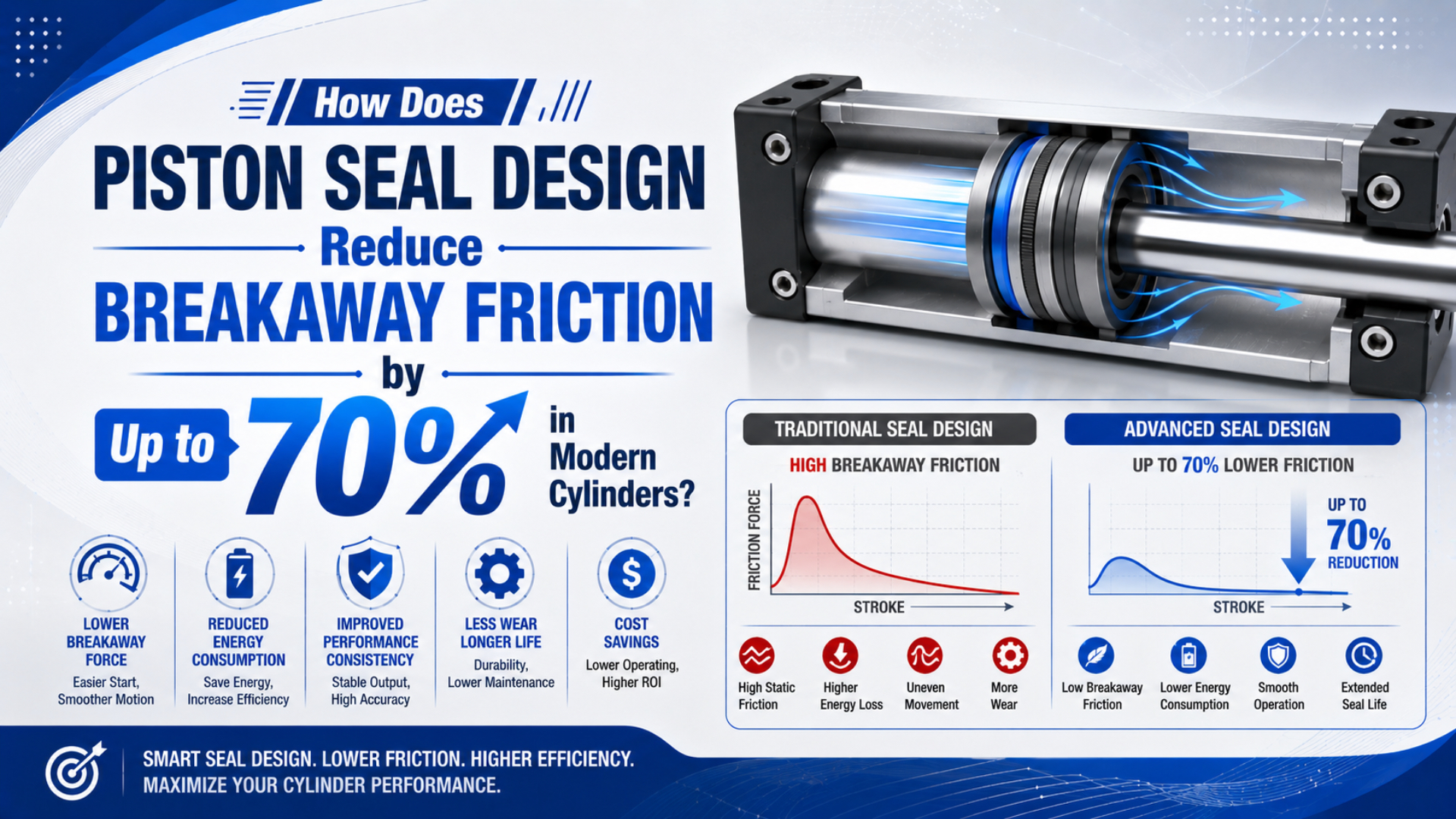
Seal architecture changes starting drag through lip contact, radial interference, pressure energization, compound choice, lubricant retention, and groove control. The headline needs a boundary. “Up to 70%” describes a matched test result. The rule applies to PTFE and polyurethane. It also applies to NBR and every other profile.
Engineering approval asks whether a candidate starts the same cylinder with less measured resistance while meeting leakage, wear, pressure, temperature, contamination, and service-life limits. A defined baseline is essential. Evidence must come from first movement after a controlled dwell, not a subjective impression that the stroke feels smoother.
Context controls the percentage.
Key Takeaways
- One 2019 study attributed 90% of friction to piston seals in its tested pneumatic-cylinder arrangements, not in every cylinder.
- A 70% reduction requires matched baseline and candidate measurements.
- Lower friction is acceptable only when leakage, wear, guidance, and life criteria still pass.
What Does “Up to 70%” Mean in a Piston-Seal Test?
Belforte and colleagues separately tested piston and rod seals in commercial pneumatic cylinders and reported that piston seals produced 90% of total friction in their arrangements. Scope matters in every comparison. The finding shows why a 70% claim must identify the baseline seal and exact test conditions (Experimental study of friction in pneumatic seals, 2019).
Breakaway-friction reduction is the relative decrease in measured resistance at the first confirmed piston movement. It compares a candidate configuration with a named baseline under the same test boundary. The percentage is calculated as:
The symbol gives the reduction in percent. Values and are the respective starting resistances in newtons. Derive them from synchronized chamber pressures and effective areas, or use a calibrated force transducer. Keep one method.
For example, a baseline cylinder may need 100 N to start after a 60-second dwell. Its candidate needs 30 N with identical pressure, temperature, direction, lubricant, and load. The reduction is 70%. Changing either dwell or grease breaks the comparison.
Measurements settle it.
A large percentage can hide a small absolute change. Reducing breakaway from 10 N to 3 N also equals 70%, but its machine value differs from reducing 300 N to 90 N. Record both the percentage and force. Then compare the remaining force margin with the real payload, opposing chamber pressure, external guides, and required acceleration.
The baseline and candidate records should match these conditions:
| Comparison boundary | What must remain controlled |
|---|---|
| Cylinder hardware | Bore, rod, stroke, piston, barrel, guides, mount, ports, and cushions |
| Seal installation | Profile, lip direction, groove, assembly tool, lubricant type, and lubricant quantity |
| Operating state | Supply pressure, both chamber pressures, temperature, direction, load, and orientation |
| Start history | Dwell time, previous motion, depressurization state, and cold or warm condition |
| Measurement | Sensor ranges, sample rate, first-motion threshold, filtering, and calculation method |
| Acceptance | External leakage, internal leakage, stroke behavior, wear, and post-test inspection |
Use the separate breakaway-force measurement guide for pressure-area calculations and extension/retraction force balance; this article evaluates how piston construction changes that starting result.
How Are Breakaway and Running Friction Different?
Experiments published in 2026 tracked position, velocity, both chamber pressures, and friction force for three pneumatic cylinders. One first peak reached about 15 N. Later peaks changed during motion. This distinguished a start threshold from resistance governed by system history (2026 Actuators study, 2026).
Starting and sliding are different.
Breakaway friction is resistance present before visible relative motion. During a dwell, lips can adhere and grease can redistribute. Elastomer stress also relaxes. Motion begins only after net pneumatic force exceeds every opposing seal, bearing, guide, load, and installation reaction.
Running friction is resistance recorded after motion begins, when speed, pressure energization, heat, and lubricant-film condition influence the interface. That distinction is practical. Easy starting can still precede unstable travel or leakage, while low running drag never guarantees release after a long dwell.
| Observed behavior | Likely quantity | What to record next |
|---|---|---|
| One high force peak after a long stop | Breakaway resistance after dwell | Dwell duration, temperature, grease, and first-motion pressure |
| Repeated stop-and-release motion | Stick-slip during running | Position, velocity, both chamber pressures, valve command, and load |
| Smooth motion but high pressure difference | Running friction or external resistance | Direction, speed, guide force, rod alignment, and exhaust pressure |
| Fault appears at one stroke location | Mechanical or surface defect | Barrel, rod, guide, cable, hose, cushion entry, and mount geometry |
| Friction changes after several cycles | Thermal or lubricant redistribution | Cycle count, surface temperature, grease migration, and seal condition |
Do not diagnose repeating stick-slip from breakaway force alone. The 2026 experiments found that airflow, source pressure, external load, initial position, and dwell-dependent static friction interact with chamber dynamics. The low-speed stick-slip diagnostic explains how to distinguish that cycle from one-time starting resistance.
When several actuators change together, inspect supply dynamics before replacing seals; the air-pressure fluctuation guide covers that evidence because no piston profile can repair a regulator, valve, tube, silencer, or shared-air fault.
Which Piston-Seal Features Change Breakaway Friction?
Parker’s pneumatic-seal catalog attributes the C2 profile’s low friction to its short contact area and directs dry-air applications toward the interchangeable E4 profile, which is intended for oil-free air after initial assembly lubrication. Those details show why a material name alone cannot predict breakaway performance (Parker Pneumatic Seals, accessed 2026).
Material names do not decide the result.
Radial interference and lip loading establish initial contact. Excess squeeze resists motion. Too little can leak or shift inside the groove, so released drawings must pair compound recovery, cross-section, and bore tolerance.
Pressure energization changes contact as chamber pressure rises. A lip or energized PTFE element may press harder against the bore under pressure. That helps sealing, but it can make friction pressure-dependent. The 2019 pneumatic-seal experiment found pressure more influential than velocity across its tested conditions, so measurements belong at working pressure rather than on an unpressurized bench. Contact geometry controls where that sealing load acts. Short contact can reduce sliding area, yet width alone is not a target. Lip angle, edge radius, hinge thickness, sealing direction, groove support, and local deformation shape the contact patch. A nominally narrow lip may spread after pressurization or thermal growth. Prototype drawings should connect predicted contact behavior with measured starting force across manufacturing tolerances and pressure states.
Compound choice alters deformation and sliding behavior. Fillers reshape wear resistance and thermal response. Parker describes PTFE as low-friction and dry-running capable, yet virgin material has little resilience, creeps under load, and wears quickly. Carbon-filled grades appear in pneumatic service, but the counterface and duty still govern selection (Parker PTFE Seals Design Guide, accessed 2026).
Lubricant retention affects the first stroke after dwell and the friction trend over repeated cycles. Parker’s Z5 piston seal uses lubricant-retaining lip geometry, while its pneumatic profiles distinguish oil-free air from dry assembly: many still require initial grease. Review the self-lubricating seal guide before adding airline oil or changing assembly grease. Groove and counterface control can defeat an otherwise suitable profile. Inspect bore roundness and finish first. Chamfers, flash, groove dimensions, assembly damage, and piston guidance follow. Side load then deserves a separate check through the cylinder side-loading guide, because tilt changes local lip pressure.
| Design input | Possible friction benefit | Failure introduced when pushed too far |
|---|---|---|
| Lower interference | Less initial contact force | Leakage, unstable lip position, poor low-pressure sealing |
| Shorter contact patch | Lower sliding area | Higher local stress or reduced tolerance margin |
| PTFE-based sliding element | Low friction and reduced stick-slip potential | Creep, wear, installation sensitivity, weak elastic recovery |
| Elastomer energizer | Maintains contact across tolerance and pressure changes | Added preload, chemical incompatibility, compression set |
| Lubricant-retaining geometry | More stable film after reversals | Contamination retention or grease migration |
| Smoother counterface | Lower abrasion and seal damage | A finish outside the seal specification may retain too little lubricant |
Low Friction Must Be Balanced Against Leakage and Wear
SMC documents stable operation down to 0.5 mm/s for selected low-speed cylinders, but the same data assigns 1 mm/s to bores of 16 mm and smaller. Size changes the limit. Series-specific evidence therefore outranks any material ranking (SMC Smooth and Low-Speed Cylinders, accessed 2026).
Friction alone cannot win.
Seal acceptance window is the range where bypass leakage remains controlled without excessive sliding resistance. Contact load can improve starting behavior until tolerance, temperature, wear, or surface variation opens an unacceptable path. Wear narrows that window further. A 2014 study developed a multi-lobed pneumatic piston seal whose initial geometry delivered low friction but less wear resistance than a commercial lip seal. Researchers revised its contact region and lubricant reservoirs before accelerated life testing (Low friction multi-lobed seal for pneumatic actuators, 2014). First-test drag and durable performance are separate verdicts.
Optimize a window, not one isolated minimum. Smooth starting defines only one edge. Leakage, wear, particle generation, heat, lost output, and service-life drift define the opposing edge, so first-friction victory can still fail machine acceptance.
Check these tradeoffs before approving a low-breakaway profile:
- Low-pressure sealing: Confirm lip energization after dwell.
- Pressure range: Check steady pressure, transients, extrusion clearance, and backup support against the released profile data.
- Wear distance: Specify cycles and accumulated travel.
- Temperature: Qualify compound recovery, energizer preload, grease viscosity, interference, and thermal growth at cold start and stabilized duty.
- Air quality: Test relevant particles, water, oil carryover, and dry-air exposure.
- Guidance: Prove that bearings carry side load through the full stroke instead of using the seal as a radial support.
- Process cleanliness: State prohibited grease, particles, and oil.
For material screening beyond friction, use the seal compatibility framework. The broader dynamic-versus-static seal guide helps keep sliding seals, barrel seals, wipers, and cushioning elements from being specified as if they served the same function.
How Should Engineers Measure and Specify a Seal Change?
ISO 19973-3 expresses pneumatic piston-rod cylinder life in cycles or kilometres and includes test equipment plus threshold levels. Apply that discipline to seal comparisons. Match the hardware, define failure, repeat measurements, and retain raw data for every released configuration (ISO 19973-3, confirmed 2026).
Begin with the machine’s approved energy-control procedure. Secure the payload and isolate every energy source before disconnecting a cylinder or pressure instrument. A breakaway test can produce sudden motion when stored pneumatic force exceeds resistance, so the test fixture, load, guards, and travel limits must be reviewed before pressure is applied.
Use this measurement sequence:
Measurement must be traceable.
- Identify the configuration. Record the cylinder code, bore, rod, stroke, profile, compound, groove revision, guidance, mount, cushions, and instrument locations.
- Define first motion. State the displacement or velocity threshold and filtering rule.
- Control history. Fix depressurization, prior direction, dwell, temperature state, and conditioning cycles so every start has the same preparation.
- Measure both chambers. Synchronize cap-end pressure, rod-end pressure, and position. Preserve supply pressure plus valve command as diagnostic channels, even when they are not part of the force calculation.
- Resolve resistance. Apply effective areas and external load consistently, or use a calibrated transducer.
- Repeat each direction. Extension and retraction have different areas; lip orientation, rod sealing, payload, gravity, and guide reactions can also reverse or change magnitude.
- Complete the duty. Measure running stability, leakage, stroke time, temperature, and low-speed behavior after the first successful start.
- Inspect promptly. Record wear and lubricant migration before cleaning.
Assembly state matters. In our experience, fresh grease or a polished bore can overshadow the profile change. New guidance and corrected alignment do the same. Those repairs may be valid, but a mixed intervention cannot attribute the measured improvement to seal geometry alone.
Write acceptance criteria before selecting the winner:
| Acceptance item | Minimum record |
|---|---|
| Breakaway | Force or pressure threshold by direction, dwell, temperature, and repeat number |
| Running motion | Mean speed, velocity variation, stops, slip distance, and chamber pressures |
| Leakage | Internal and external method, pressure, stabilization time, and allowable limit |
| Durability | Cycles, accumulated travel, load, speed, inspection interval, and failure threshold |
| Condition | Seal wear, bore marks, grease movement, guide wear, and particle evidence |
| Traceability | Seal lot, compound, drawing revision, lubricant, cylinder code, and sensor calibration |
Build the RFQ from measured evidence. Identify the cylinder and seal codes; add bore, groove, pressure, speed, stroke, dwell, duty, temperature, air quality, lubricant, payload, orientation, guidance, breakaway results, leakage limit, life target, and allowed materials. Attach photographs before cleaning. Keep units explicit.
If matched testing shows 100 N for the baseline and 30 N for the candidate, a 70% statement is mathematically correct for that configuration. Release it only when leakage, running motion, wear, and durability also pass. Without those boundaries, “up to 70%” remains a headline rather than an engineering specification.
Evidence closes the loop.
Claims need context.
Publisher details and a route for technical corrections are available through About Us and Contact.
Piston Seal Breakaway Friction FAQs
The 2019 pneumatic-seal study found pressure more influential than velocity in its experiments. A 2026 three-cylinder study also connected dwell-dependent static friction with stick-slip. Consequently, these answers treat breakaway as a condition-specific measurement rather than a fixed fraction of theoretical force (Tribology International, 2019; Actuators, 2026).
Does PTFE automatically reduce piston-seal breakaway friction by 70%?
No. Parker identifies PTFE as low-friction but documents creep and limited resilience. Fillers alter the balance. Finished performance still depends on energizer, profile, interference, counterface, groove, pressure, lubricant, and counterface preparation. For instance, matched testing alone can establish a 70% reduction for one released configuration.
How is a 70% breakaway-friction reduction calculated?
Calculate the difference and divide it by baseline before multiplying by 100%. From 100 N to 30 N is 70%. That is the arithmetic. Keep every boundary identical: cylinder, direction, dwell, temperature, lubricant, pressure method, external load, and first-motion threshold.
Is breakaway pressure the same as breakaway force?
No. Breakaway pressure is one chamber reading at first motion. Force requires both chamber pressures and their effective piston areas. Rod-side area differs. External load direction also changes the balance, so synchronize pressure with position instead of treating one gauge value as total resistance.
Can lubrication reduce breakaway without changing the piston seal?
Yes. Grease type, quantity, distribution, and dwell can change initial resistance, which is why lubrication must remain controlled in an A/B seal test. Some non-lube cylinders still receive grease during assembly. Do not add airline oil unless the exact cylinder instructions permit it and maintenance can keep the new regime continuous.
What must pass after installing a low-friction piston seal?
Verify both directions after defined dwells. Continue with running stability, internal and external leakage, stroke time, temperature, cushioning, and loaded performance. ISO 19973-3 ties reliability results to equipment and thresholds; explicit acceptance limits and retained calibration records make that evidence auditable.
Sources and technical references
- Belforte et al., “Experimental study of friction in pneumatic seals”, Tribology International 135, 432-443, 2019; retrieved 2026-07-19.
- Belforte et al., “Low friction multi-lobed seal for pneumatic actuators”, Wear 320, 7-15, 2014; retrieved 2026-07-19.
- Ngoc, Pham, and Xuan, “Experimental and System-Level Simulation Study of Stick-Slip Characteristics in Pneumatic Cylinders”, Actuators 15(5), 243, 2026; retrieved 2026-07-19.
- ISO 19973-3:2015, reliability testing and reporting for pneumatic piston-rod cylinders; confirmed 2026, retrieved 2026-07-19.
- Parker Pneumatic Seals Catalog PTD3351, piston-seal geometry, materials, lubrication, and installation boundaries; retrieved 2026-07-19.
- Parker PTFE Seals Design Guide PTD3354, PTFE friction, creep, wear, fillers, and application boundaries; retrieved 2026-07-19.
- SMC Smooth Cylinder and Low-Speed Cylinder Data, configured minimum-speed and output-force data; retrieved 2026-07-19.