

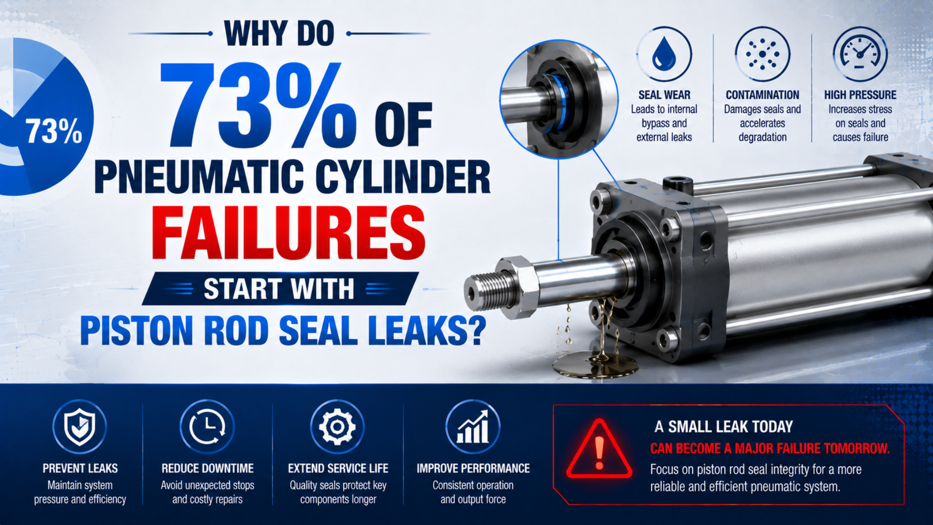
They don’t, at least not on the evidence available. The published source once used for the 73% figure now returns a 404 response, and current manufacturer troubleshooting documents do not report that percentage. Piston rod seal leakage is still a serious, visible symptom, but treating it as the cause of nearly three quarters of cylinder failures can send maintenance teams toward the wrong repair.
A better question is: where is the air escaping, when does it appear, and what physical evidence sits behind it? A cut rod seal, scratched rod, worn guide bushing, misaligned load, contaminated air supply, incompatible lubricant, or excessive temperature can produce similar symptoms. The failed seal may be the damaged part without being the initiating fault.
Key Takeaways
- The 73% claim cannot be verified from its cited source.
- Diagnose four possible leak paths before condemning the rod seal.
- One-sided wear points toward alignment or guidance; scratches point toward rod damage or particles.
- Correct the cause, install the specified service parts, and verify the cylinder under representative load.
Does Evidence Support the 73% Cylinder-Failure Claim?
The cited 73% source is unavailable, while a current 2022 Plant Services review names 4 broad cylinder-failure paths: side loading, excessive pressure, seal problems, and improper tie-rod torque (Plant Services, 2022). It gives no universal percentage for rod-seal failures in pneumatic cylinders.
Piston rod seal leakage is unintended air loss where the moving rod passes through the cylinder head or gland. It describes a leak location, not a complete root-cause diagnosis. Rod condition, pressure-seal condition, guide support, alignment, contamination, material, temperature, lubricant, and assembly can all affect that interface.
That distinction matters. A statistic in a headline looks precise, but a useful failure rate requires a defined population, cylinder type, duty, environment, failure criterion, and observation period. A packaging cylinder in a washdown area and a low-cycle clamp in a clean assembly cell do not share the same exposure.
The strongest defensible statement is narrower: piston rod seal leakage is one common external failure symptom, and its root cause can lie outside the seal. Parker’s pneumatic actuator troubleshooting guide traces rod-seal leakage to worn or damaged seals, rough or scored rods, excessive gland clearance, incompatible fluids, and excessive temperature (Parker Pneumatic Actuator Catalog, accessed 2026).
The number is less useful than the failure boundary. If a maintenance record simply says “seal failed,” it hides whether the evidence began at the rod surface, guide bushing, air supply, material choice, assembly process, or external load. Record the initiating condition separately from the component that finally leaked.
Is the Air Really Escaping Past the Piston Rod Seal?
SMC’s CM2Y troubleshooting table separates 4 relevant branches: piston-seal leakage, rod-seal leakage, insufficient pressure, and faults elsewhere in the system (SMC CM2Y Manual, accessed 2026). That separation should happen before a seal kit is ordered or the cylinder is dismantled.
Start with a safe observation of the installed machine. Note whether the leak is audible at the rod-end gland, a cylinder port, the directional valve exhaust, a tube connection, or another nearby component. Sound can travel through a frame or enclosure, so use an approved leak-detection method rather than relying on hearing alone.
| Observation | More likely path | Next confirmation |
|---|---|---|
| Air is detected at the rod where it exits the head | Rod seal, rod surface, gland, or guide-related leakage | Inspect rod condition, seal lip, guide clearance, and installed alignment |
| Air continues from the opposite cylinder port at end of stroke | Piston-seal bypass or bore damage | Isolate and test according to the cylinder manufacturer’s procedure |
| Air appears at the valve exhaust when the cylinder should be holding | Cylinder bypass or valve leakage | Separate cylinder and valve branches with an approved circuit test |
| Bubbles appear at a fitting, tube, flow control, or end-cap joint | Connection or static-seal leakage | Repair that interface before blaming the dynamic rod seal |
| Cylinder drifts without visible rod-end leakage | Internal bypass, valve leakage, or load/control behavior | Check the complete circuit and load-holding design |
Parker recommends pressurizing one side and observing the opposite disconnected port when checking suspected piston-seal bypass, but that is a service procedure, not an invitation to open a live circuit casually. Follow the exact product manual, isolate hazardous motion, and control stored pneumatic and mechanical energy first.
For a wider circuit-level sequence, use the pneumatic cylinder fault-troubleshooting workflow. The cylinder sealing-system guide explains how the rod seal, wiper, piston seal, wear ring, and static seals divide the work.
What Does the Timing of a Rod-End Leak Reveal?
Parker groups cylinder-seal leakage into at least 5 observable behaviors: slow uniform, gradually increasing, sudden copious, erratic, and stick-slip-related symptoms (Parker Mobile Cylinder Service Guide, accessed 2026). The guide is hydraulic, but its evidence-first timing categories are useful diagnostic prompts, not pneumatic failure-rate statistics.
Timing does not identify a cause by itself. It decides what to preserve and measure next.
| Leak behavior | More consistent with | Check next |
|---|---|---|
| Begins immediately after seal replacement | Cut or twisted lip, wrong orientation, damaged assembly edge, wrong part, contaminated groove | Service-kit identity, installation tools, chamfers, groove, lubricant, seal orientation |
| Increases gradually over weeks or cycles | Progressive wear, rod scoring, guide clearance, contamination, material aging | Rod finish, wear direction, wiper, particles, guide bushing, duty history |
| Appears mainly near full extension | Side load, bent rod, misaligned external guide, growing bending moment | Alignment and guide freedom through the full stroke under load |
| Appears after warm-up | Temperature limit, lubricant change, material softening or hardening, thermal alignment shift | Rod-end temperature, ambient exposure, material code, lubricant, hot alignment |
| Appears only after washdown or chemical cleaning | External ingress, swollen material, incompatible cleaner, lubricant removal | Cleaner identity and concentration, exposure direction, seal and wiper compatibility |
| Starts suddenly after impact or jam | Rod nick, bent rod, guide or bearing damage, extruded or torn seal | Rod runout, impact marks, mount movement, bushing clearance, cushion condition |
| Stops and returns intermittently | Debris under the lip, eccentric loading, temperature cycling, unstable connection | Preserve particles and installed orientation; compare leak with stroke and load |
Ask when the symptom started relative to the last maintenance event, tool crash, product change, cleaning-chemical change, pressure adjustment, speed increase, or guide repair. That timeline often narrows the investigation faster than inspecting a loose seal on a clean bench.
In our experience, three details are easily lost: the seal’s clock position, the cylinder’s installed orientation, and the exact stroke position where leakage grows. Photograph those before cleaning. A one-sided mark becomes much more useful when it can be matched to gravity, load offset, guide reaction, or a damaged sector of the rod.
Wear Patterns: Treat the Seal as Evidence
Festo’s 56-page DSBC repair instruction requires a visual check for deposits, scoring, rod warping, ambient attack, and other function-impairing damage before repair (Festo DSBC Repair Instructions, accessed 2026). A discarded or washed seal cannot preserve all of that evidence during teardown.
Inspect the seal, wiper, rod, guide bushing, head or gland, and nearby deposits as a set. Do not diagnose by seal color alone. Photograph both the pressure side and atmosphere side, mark the installed direction, and retain representative debris in a clean labeled container when the maintenance procedure allows it.
| Physical evidence | More consistent with | What would strengthen the diagnosis |
|---|---|---|
| Uniform circumferential polishing | Service wear, unsuitable material, lubrication condition, or general contamination | Cycle and time record, material identity, temperature, rod finish |
| Wear concentrated on one sector | Misalignment, side force, bent rod, or worn guide bushing | Matching bushing polish, rod score direction, load direction, measured alignment |
| Long axial scratches on the rod | Hard particles, damaged wiper, burr, or biased metal contact | Embedded debris, damaged wiper lip, matching scratch through the stroke |
| Clean cut or nick near the seal lip | Sharp assembly edge or tool damage | Immediate post-repair leakage and a matching burr or chamfer defect |
| Soft, swollen, or sticky material | Chemical or lubricant incompatibility | Known material code, exposure record, supplier compatibility data |
| Hard, cracked, or low-elasticity material | Excessive temperature, aging, ozone, or unsuitable compound | Measured temperature history and model-specific material limit |
| Rod can rock visibly at the head | Excessive guide clearance or damaged head | Manufacturer’s measurement procedure and service limit |
The adjacent guide on rod bearings and repeat rod-seal failures goes deeper into one-sided wear, guide clearance, and external load paths. For internal surface damage, use the barrel-scoring and piston-damage workflow.
How Do Contamination and Air Quality Damage the Rod End?
ISO 8573-1:2010 classifies compressed-air purity around 3 primary contaminant groups: particles, water, and oil (ISO 8573-1). It does not prescribe one universal class for every cylinder, so maintenance must compare the measured point-of-use condition with the selected actuator’s requirements.
Internal contamination and external contamination take different routes. Particles in the air supply can reach valves, ports, the bore, and seals. External dust, chips, weld spatter, coolant, cleaner residue, or abrasive product can collect on the exposed rod and be carried toward the wiper and pressure seal.
A filter bowl on the machine does not prove suitable air reaches the actuator. Check the required particle, water, and oil classes at a named measurement point. Inspect drains, differential pressure, element condition, downstream piping, recent maintenance debris, tube preparation, and whether a lubricator was added or removed against the cylinder manufacturer’s instructions.
The rod wiper and rod pressure seal are not interchangeable. Trelleborg describes pneumatic rod seals as lip seals or combined seal-scraper designs, with material and geometry selected for friction, abrasion, and operating conditions (Trelleborg Pneumatic Rod Seals, accessed 2026). A wiper may limit ingress, but it cannot compensate for a badly scored rod or unsuitable exposure.
For a broader point-of-use air-quality plan, see the coalescing-filter guide for critical compressed air. Do not automatically add finer filtration or lubrication without checking flow loss, dryer performance, required purity, and component instructions.
Why Do Side Load and Misalignment Cause Repeat Leakage?
SMC’s cylinder instructions identify 4 parts that can wear when the rod and load axes do not match: the tube inner surface, bushing, rod surface, and seals (SMC Cylinder Safety Instructions, accessed 2026). A new seal cannot realign any of them.
Side load pushes the rod toward one side of the guide bushing. The seal lip then sees uneven contact, while the rod or bushing may polish, score, or wear in the same clock position. The problem can grow near full extension because the unsupported length and bending effect increase.
Check centerline alignment at retracted, mid-stroke, and extended positions. Repeat the check under representative load and after the machine reaches operating temperature. A bracket that looks aligned while unloaded may deflect during production. A rigid connection can also force the rod to follow a path set by a nonparallel external guide.
SMC recommends matching the rod and load movement directions and considering a floating joint within its allowable eccentricity and angle. A floating joint absorbs limited connection error; it does not carry a large lateral force or overturning moment. When the load needs guidance, choose an external guide or guided cylinder using model-specific load and moment data.
Replacing only the seal can create a misleading success. The fresh lip briefly conforms to the biased rod, so leakage disappears during commissioning. If the guide, mount, rod surface, and bushing remain unchanged, the same directional wear pattern returns. Treat repeat leakage as evidence that the load path was never closed.
Do Material, Temperature, and Lubricant Match the Application?
Parker’s pneumatic seal catalog devotes more than 100 pages to seal compounds, rod seals, wipers, piston seals, cushioning seals, and guiding elements, and warns that special pressure, temperature, speed, water, and fluid conditions require application-specific selection (Parker Pneumatic Seals, accessed 2026).
Generic statements such as “use NBR below this temperature and FKM above it” are not enough. Compound formulation, seal profile, rod finish, speed, pressure, lubricant, cleaning chemicals, humidity, ozone, and duty all matter. Use the exact cylinder series and service-kit data, not a visual match or material abbreviation alone.
Preserve the failed part number when available. Record operating temperature near the rod end, not only room temperature. List every lubricant, compressor oil, washdown chemical, process fluid, adhesive, coolant, and cleaning concentration that can reach the rod or internal air path. Ask whether the exposure is continuous, intermittent, or created only during sanitation.
Material condition offers clues but not proof. Swelling or softness raises a compatibility question. Hardening and cracking raise temperature, aging, ozone, or unsuitable compound questions. A clean cut raises an assembly question. Compare the observation with supplier compatibility data and the model’s limits before choosing a replacement.
The temperature and seal-material selection guide covers thermal effects in more depth. The industrial cylinder seal types guide helps distinguish the service roles before an RFQ is prepared.
How Can Installation Create a New Leak?
Festo’s DSBC repair instruction contains 56 pages and explicitly warns against pointed or sharp-edged assembly aids because they can damage sealing lips and guide surfaces (Festo DSBC Repair Instructions, accessed 2026). Correct parts can still fail immediately when the repair process damages them.
Before work begins, follow the machine’s energy-control procedure. ISO 4414:2010 covers significant hazards associated with pneumatic systems and applies safety principles to design, installation, adjustment, operation, maintenance, and cleaning (ISO 4414, confirmed 2021). Depressurizing one line is not enough when trapped pressure, gravity, springs, tooling, or suspended loads can still move.
Use the model-specific repair instructions and complete service kit. Clean the work area and parts with approved materials. Protect the seal from threads, keyways, retaining-ring grooves, burrs, and sharp chamfers. Use only the specified assembly grease and orientation. Do not stretch, twist, trim, or substitute a seal because it appears close in size.
Inspect these surfaces before assembly:
- Rod for dents, corrosion, scoring, plating loss, burrs, and straightness concerns.
- Guide bushing or bearing for one-sided wear and excessive clearance.
- Seal groove and gland for damage, contamination, and dimensional distress.
- Wiper and external protection for the actual environmental exposure.
- Tube, piston guidance, cushions, mounts, and external guide when evidence points beyond the rod end.
Festo directs users to replace the complete cylinder when the barrel is significantly damaged. Other limits remain model-specific. If the rod, gland, pressure boundary, or guide condition falls outside the manufacturer’s repair criteria, compare a qualified rebuild with replacement instead of forcing a service kit into damaged hardware. The repair-versus-replace framework can structure that decision.
Return-to-Service Verification Checklist
ISO 10099:2001 defines final examination and acceptance criteria for double-acting, single-rod pneumatic cylinders and was reconfirmed in 2023 (ISO 10099). Field acceptance still needs the exact cylinder manual, machine risk controls, operating conditions, and a documented leak criterion rather than a vague “looks good” sign-off.
Verify progressively, using an approved commissioning procedure:
- Part identity: Confirm cylinder model, bore, stroke, rod option, service-kit code, seal material, lubricant, and installed orientation.
- Mechanical condition: Confirm mounts, pivots, rod connection, external guides, hard stops, rod surface, and permitted clearances.
- Safe low-energy motion: Where the procedure allows it, check for binding, abnormal sound, impact, and interference before representative production energy is applied.
- Leakage paths: Test the rod end, fittings, end-cap joints, opposite port, and valve exhaust with the specified method and acceptance limit.
- Dynamic pressure and flow: Measure at the actuator during motion when required; a regulator gauge upstream may hide restriction or pressure loss.
- Representative load: Verify full stroke, speed, cushioning, sensor switching, holding behavior, and repeatability with the intended payload and duty.
- Warm-state check: Repeat critical observations after operating temperature stabilizes when the original leak was heat-related.
- Baseline record: Save measurements, photographs, parts used, corrective action, and acceptance results so a future leak can be compared with a known-good state.
Do not use a production shift as an uncontrolled endurance test. If leakage, heat, binding, pressure loss, or abnormal impact returns, stop and reopen the relevant branch. The goal is not merely a dry rod at idle; it is a cylinder that passes defined checks across its real load and operating cycle.
Piston Rod Seal Leak FAQs
Parker’s troubleshooting catalog separates external rod-seal leakage from piston bypass and other system faults, while ISO 10099 applies final examination criteria to double-acting single-rod cylinders (Parker; ISO). These 5 answers keep symptom, evidence, repair, and acceptance separate during maintenance triage.
Are 73% of pneumatic cylinder failures caused by piston rod seal leaks?
No reliable public source was found for that exact percentage, and the URL originally used to support it is unavailable. Rod-seal leakage is a common visible symptom, but published troubleshooting documents identify several initiating conditions, including rod damage, guide wear, misalignment, contamination, material incompatibility, temperature, pressure, and installation damage.
How do I distinguish a rod-seal leak from piston-seal bypass?
A rod-seal leak is detected where the rod exits the cylinder head. Piston bypass is internal and may appear as flow at the opposite port or valve exhaust under a manufacturer-approved isolation test. Fittings, static joints, and valve leakage can imitate either symptom, so localize the air before dismantling the cylinder.
Why does a new rod seal start leaking again?
Repeat leakage often means the initiating condition remained. Check for a scored or bent rod, one-sided bushing wear, excessive guide clearance, misaligned load, external contamination, unsuitable material, wrong lubricant, damaged groove, sharp assembly edge, or incorrect seal orientation. A new lip cannot correct geometry or damaged running surfaces.
Can I select a replacement seal by dimensions and material alone?
No. Dimensions and a generic material name do not fully define the profile, lip geometry, hardness, compound, friction, pressure direction, speed capability, groove fit, lubricant compatibility, or environmental resistance. Use the exact cylinder series and approved service-kit information, then verify temperature, media, cleaning chemicals, duty, and rod condition.
What should be recorded after a successful repair?
Record the cylinder and kit codes, failure evidence, measured rod and guide condition, corrected root cause, pressure during motion, load, speed, temperature, leakage-test method, acceptance limit, cushioning, sensor operation, and warm-state result. Photographs and a dated baseline make the next inspection a comparison instead of another guess.
Sources and technical references
- Parker Pneumatic Actuator Products Catalog 0900P-4, maintenance and troubleshooting sections, accessed 2026-07-19.
- Parker Pneumatic Seals Catalog PTD3351, seal selection and installation guidance, accessed 2026-07-19.
- SMC CM2Y Series Operation Manual, troubleshooting branches for rod and piston leakage, accessed 2026-07-19.
- SMC Cylinder Safety Instructions, alignment, lateral-load, and guidance precautions, accessed 2026-07-19.
- Festo DSBC Repair Instructions, inspection, disassembly, seal protection, and repair boundaries, accessed 2026-07-19.
- ISO 8573-1:2010, compressed-air contaminant and purity classes, accessed 2026-07-19.
- ISO 4414:2010, pneumatic-system safety requirements, accessed 2026-07-19.
- ISO 10099:2001, pneumatic-cylinder final examination and acceptance criteria, accessed 2026-07-19.
- Trelleborg Pneumatic Rod Seal and Scraper Combinations, component function and material context, accessed 2026-07-19.
- Plant Services, How to Prevent Cylinder Failure, cylinder-failure mechanisms, 2022, accessed 2026-07-19.