

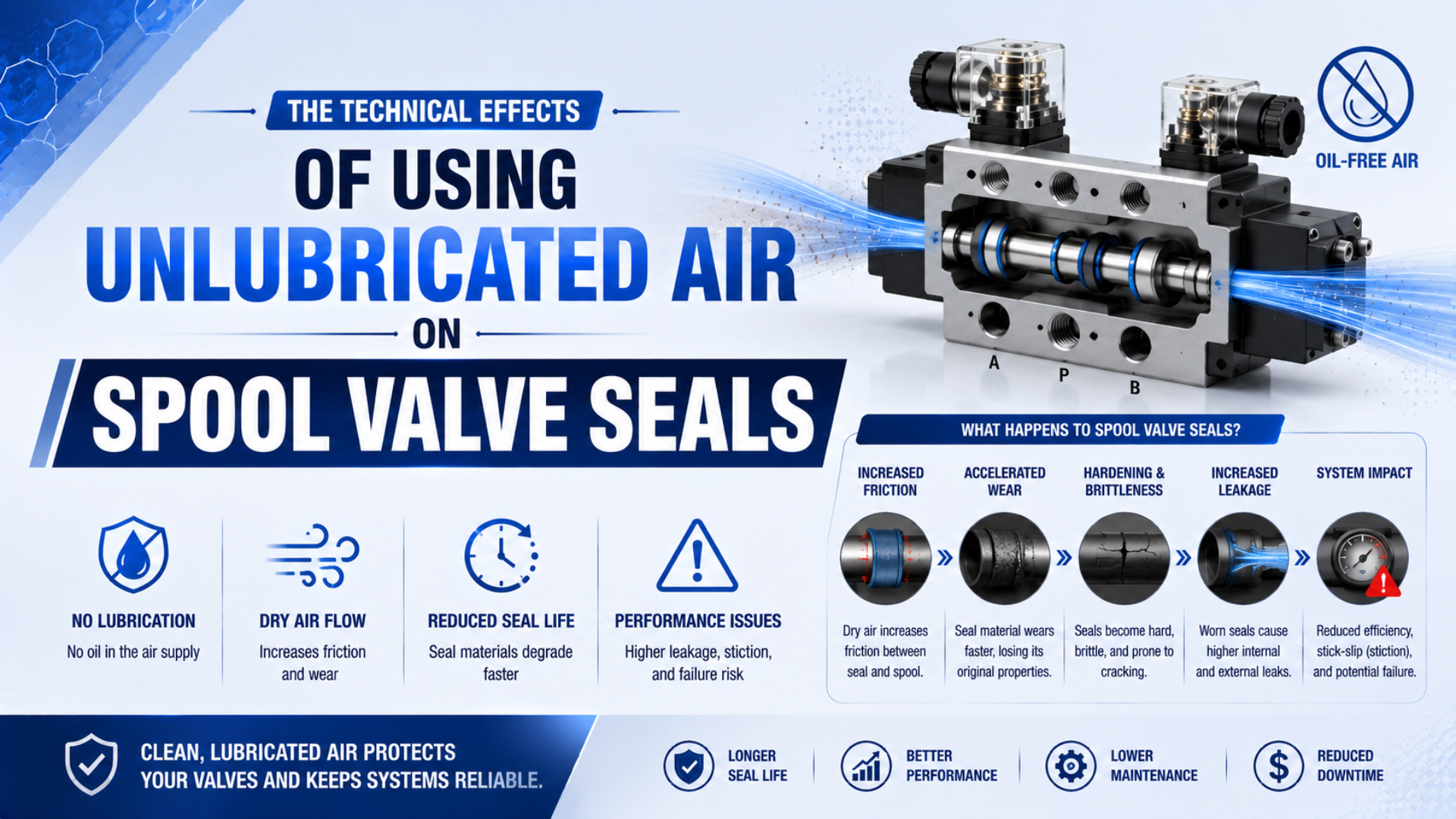
Unlubricated supply air does not automatically damage a spool valve. Many pneumatic valves are assembled with long-life grease and are designed to run without an airline lubricator. Trouble begins when the actual air quality, seal construction, lubricant history, or duty falls outside the limits of the exact valve model.
Unlubricated supply air means that no oil mist is intentionally added at the point of use. It does not prove that the air is free of compressor oil, that the air has a low pressure dew point, or that the valve contains no factory-applied lubricant.
This distinction changes the maintenance question. Instead of asking whether every spool seal needs oil, identify the valve, its sealing principle, its approved compressed-air class, and whether anyone has added or stopped airline lubrication since commissioning.
Key Takeaways
- ISO 8573-1 treats particles, water, and oil as 3 separate purity dimensions.
- A non-lube valve can still depend on factory-applied grease.
- Friction, leakage, response, and life cannot be assigned universal dry-air multipliers.
- Once airline oil is introduced, some manufacturers require it to continue.
What Does Unlubricated Air Actually Mean for a Spool Valve?
ISO 8573-1:2010 defines compressed-air purity separately for particles, water, and oil, so “unlubricated” describes only one part of the operating condition (ISO 8573-1, 2010). A valve can receive no deliberate oil mist yet still see moisture, particles, compressor carryover, or retained assembly grease.
Four terms are frequently mixed together:
| Term | What it should mean | What it does not prove |
|---|---|---|
| Unlubricated supply air | No lubricator intentionally meters oil into the branch | Zero oil carryover or no grease inside the valve |
| Non-lube valve | The specified valve can operate without routine airline oil under stated conditions | Grease-free construction or unlimited air dryness |
| Oil-free compressed air | Oil concentration meets a stated class at a stated sampling point | Low water content, low particle count, or process cleanliness |
| Dry compressed air | Water content or pressure dew point meets a stated limit | Absence of oil or suitability for every valve lubricant |
That vocabulary matters because changing one state doesn’t automatically change the others. Removing an airline lubricator may leave residual oil in piping. Installing a desiccant dryer may reduce water vapor without changing the deliberate oil-feed policy. A coalescing filter may reduce aerosol carryover but cannot certify the valve’s internal grease condition.
For a wider treatment of these air-quality terms at cylinder level, see the guide to dry, non-lubricated air in pneumatic cylinders. The valve decision must still be made from its own model documentation.
The useful system boundary is the complete lubrication state: factory grease, deliberate airline oil, incidental carryover, cleaning exposure, air purity, and duty. Calling the branch “dry” or “oil-free” without those fields hides the condition that the spool seal actually experiences.
What Keeps the Seal Sliding When No Airline Oil Is Added?
SMC’s SYJ700 manual states that the valve is lubricated for life at the factory and does not require external lubrication (SMC SYJ700 Operation Manual, accessed 2026). In that design, retained factory lubricant and the complete sliding interface support operation without routine oil mist.
A soft-sealed spool valve is a tribological assembly, not just a rubber ring. Its behavior depends on the seal compound and profile, spool finish, bore or sleeve finish, seal squeeze, lubricant type and quantity, pressure, dwell time, temperature, switching rate, pilot force, and contamination. Parker explains that a film between an elastomer and its sliding surface helps protect against abrasion, frictional heating, and rapid wear (Parker O-Ring Handbook, accessed 2026). The handbook also identifies surface finish, compound, pressure, speed, geometry, and downtime as interacting variables. No seal-family label or standalone friction coefficient captures that complete interface.
Factory-applied grease has several jobs:
- reduce direct contact during initial movement and low-speed sliding;
- limit breakaway friction after dwell;
- protect the seal during assembly and early cycling;
- retain a controlled film where the valve design provides small lubricant reservoirs;
- support sealing without continuously adding oil to the air stream.
Factory-lubricated non-lube service means the original lubricant charge is intended to support the documented operating envelope without routine oil mist. It isn’t an unlimited-life promise. Solvent cleaning, incompatible oil, extreme dryness, excessive heat, abrasive contamination, or unapproved disassembly can disturb that state.
Seal Contact, Friction, and Leakage
Parker divides dynamic seal motion into boundary, mixed, and hydrodynamic friction regimes, while noting that fully hydrodynamic operation is rarely achieved in O-ring service (Parker O-Ring Handbook, accessed 2026). Spool behavior therefore changes with film thickness, dwell, speed, pressure, surface finish, and seal geometry.
When the available film becomes thinner, breakaway force can rise and low-speed movement can become less consistent. That does not mean the air alone has “dried out” the seal. The observed effect may come from grease displacement, contamination, a changed compound, cold temperature, long dwell, loss of pilot margin, or damage to the spool surface.
The practical outputs are coupled:
| Observable output | Lubrication-related mechanism | Why the symptom is not conclusive |
|---|---|---|
| Higher breakaway pressure | Less film or greater seal adhesion after dwell | Low pilot pressure, cold grease, swollen seals, or misassembly can look similar |
| Slower switching | More resisting force or pilot-stage contamination | Coil voltage, exhaust restriction, tubing volume, and supply pressure also affect time |
| Internal leakage | Wear, scoring, seal damage, or loss of contact | Valve lap, contamination, damaged seats, and manifold seals must be separated |
| Erratic low-speed motion | Repeated stick and release at the seal interface | Control instability, pressure fluctuation, or a sticky pilot stage may be responsible |
| Rising local temperature | Increased sliding loss during rapid cycling | Coil heating, hot ambient air, and excessive switching rate are competing causes |
Seal friction and leakage pull in opposite directions. Reducing contact force can lower friction but may weaken sealing. Increasing squeeze can improve static sealing yet raise the pilot force needed to shift the spool. This is why material-only substitutions and generic “low-friction” replacement seals are risky.
If total machine response is the complaint, separate valve motion from coil delay, tubing fill time, actuator motion, and sensor confirmation. The solenoid valve response-time measurement guide provides that wider timing boundary.
Why Does Valve Construction Change the Dry-Running Risk?
SMC’s VQZ catalog identifies a stainless-steel spool and sleeve for its metal-seal version, but an aluminum and HNBR spool valve for the rubber-seal version (SMC VQZ Catalog, accessed 2026). Those interfaces cannot share one universal lubrication or leakage rule in service.
SMC describes rubber-seal spool valves as having low air leakage because the spool seal slides, while it associates metal-seal designs with long service life from a metal spool sliding in its mating surface (SMC Solenoid Valve Selection Guide, accessed 2026). These are design-level distinctions, not guarantees for an unspecified valve.
| Valve construction | Main sliding or sealing interface | Specification questions |
|---|---|---|
| Elastomer soft-sealed spool | Elastomer or bonded seal moves against a bore or sleeve | Exact compound, grease, allowable oil, air class, dwell, switching rate, leakage limit |
| Metal-sealed spool and sleeve | Closely fitted metal surfaces control flow and leakage | Clearance, contamination sensitivity, permitted oil state, leakage definition, filtration |
| Poppet or seat valve | A moving seal opens or closes against a seat | Seat material, opening force, contamination tolerance, media, permissible lubricant |
For example, part numbers still matter within one category. Festo’s VUVS-L20-M32C-MD-G18-F7 is a soft-sealed piston gate valve rated for 2.5 to 10 bar and compressed air to ISO 8573-1 [7:4:4] (Festo VUVS Product Data, accessed 2026). Those values belong to that configuration, not every VUVS option or every spool valve.
The spool versus poppet valve comparison explains the broader architecture choice. For lubrication review, continue down to the exact sealing principle, material code, pilot arrangement, and product manual.
How Should Air Quality Be Specified?
ISO 8573-1 uses 3 primary contaminant dimensions, particles, water, and oil, and applies them at the location where the air is specified or measured (ISO 8573-1, 2010). A maintenance note that says only “clean dry air” cannot establish the valve’s actual operating boundary.
Use the valve datasheet first. Festo specifies ISO 8573-1 [7:4:4] for the cited VUVS model, while SMC calls for a 5 micrometer or finer upstream filter in its general solenoid-valve precautions and warns that extremely dry air can reduce internal lubrication reliability (Festo VUVS Product Data; SMC Valve Precautions, accessed 2026).
Point-of-use air quality is the measured contaminant condition at the valve or other governed component, not merely at the compressor room or dryer outlet. Record these fields there:
- particle class or manufacturer filtration requirement;
- water class or pressure dew point at operating pressure;
- total oil class, including aerosol, liquid, and vapor where applicable;
- sampling location, operating pressure, air temperature, instrument, and date;
- deliberate lubricator state and known compressor-oil carryover;
- the valve and pilot-air part numbers governed by the result.
Relative humidity in the plant is not a substitute for compressed-air water class or pressure dew point. Neither is a dryer-outlet certificate sufficient when downstream receivers, old piping, cross-connections, or cold sections can change the point-of-use condition.
The site’s ISO 8573-1 air-quality guide covers class notation in more detail. When aerosol carryover is the concern, review the coalescing-filter guide without assuming that filtration authorizes a different valve lubricant.
What Happens When Airline Lubrication Is Added or Stopped?
Festo permits lubricated operation for the cited VUVS model but says lubricated operation must always continue once initiated (Festo VUVS Product Data, accessed 2026). SMC gives the same continuity warning and specifies Class 1 turbine oil without additives, ISO VG32, for applicable valves (SMC SYJ700 Operation Manual, accessed 2026).
Adding an oil mist can change the factory-lubricated state. The introduced oil may redistribute or displace the original grease, alter seal swell and friction, transport contamination, collect in a pilot stage, and appear at exhausts. SMC specifically warns that excessive oil can accumulate in the pilot valve and cause malfunction or response delay.
Stopping an established oil feed is also a change. Residual oil concentration will fall gradually along the branch, and components may not all reach the new state at the same time. A valve that ran acceptably with continuous oil should not be assumed to return safely to its original factory-greased condition.
Before adding, removing, or changing oil:
- identify every component downstream of the change;
- obtain the permitted oil grade and feed rule for every affected part number;
- check process restrictions on exhaust oil, silicone, food contact, paint, optics, and cleanroom use;
- document the existing grease and oil history where known;
- establish switching-time, leakage, pressure, and temperature baselines;
- define how the branch will be rebuilt or replaced if the new state fails.
For hardware placement and service checks after lubrication has been approved, use the filter-regulator-lubricator maintenance guide. A lubricator is not a diagnostic treatment for an unexplained slow valve.
Lubrication is a branch-level configuration, not a knob setting. One oil-feed change can affect the main spool, pilot valve, silencers, actuators, vacuum devices, exhaust collection, and the process itself. Approval must follow the air path, not stop at the component that first showed a symptom.
Diagnosing a Suspected Lubrication Failure
ISO 19973-2:2015 assesses directional-control-valve reliability under defined tests and normally expresses valve life in cycles, not a universal number of years (ISO 19973-2, confirmed 2026). A lubrication diagnosis therefore needs repeatable operating conditions, a failure threshold, and comparison data from the exact valve.
Start with the failure mode, not the presumed cause. Record whether the problem is failure to shift, delayed switching, external leakage, internal port leakage, coil overheating, pilot exhaust leakage, noise, or intermittent recovery after pressure changes.
Then test competing causes in a controlled order:
| Symptom | Lubrication-related possibility | Checks before condemning the spool seals |
|---|---|---|
| Valve fails after a long dwell | Higher breakaway friction or grease change | Actual pilot pressure, coil voltage, manual override, cold temperature, contamination |
| Response time has increased | More sliding resistance or oil in pilot stage | Dynamic supply pressure, exhaust silencer, coil power, command timing, tubing volume |
| Internal leakage rises | Seal wear, scoring, swelling, or loss of contact | Correct valve state, port identification, manifold gasket, contamination, test pressure |
| Leakage appears only when warm | Viscosity or seal-contact change | Coil temperature, ambient heat, duty cycle, material expansion, pressure variation |
| Several valves fail together | Shared oil, air-quality, or contamination change | Dryer service, filter bypass, compressor event, cleaner exposure, cross-connected branch |
Do not raise supply pressure as the first repair. Extra pressure may restore motion while increasing stored energy, leakage, impact, and air use. Measure dynamic pressure at the valve supply and pilot ports, then compare it with the minimum stated for the exact configuration.
When inspection is justified, preserve evidence. Photograph the spool orientation and deposits, keep removed seals labeled by location, record the lubricant and cleaner history, and inspect the bore or sleeve for directional scoring. Don’t wash the parts before the failure pattern is documented.
How Should a Valve Be Qualified After an Air-Quality Change?
ISO 19973-2 identifies 2 essential reporting dimensions for directional-valve reliability: defined test procedures and stated threshold levels (ISO 19973-2, 2015). A dryer, filter, compressor, or lubricator change should therefore be released against documented acceptance limits rather than a claim such as “three times longer life.”
Valve qualification is a controlled comparison between documented operating states. Capture a stable baseline before the change whenever possible. Use the same valve, load, pressure, temperature, switching command, dwell pattern, and measurement method after the new air condition reaches the point of use.
At minimum, compare:
- switching time after short and long dwell;
- supply and pilot pressure during actuation;
- coil voltage and command timing;
- internal leakage in each commanded state;
- external leakage at the valve and manifold;
- cold-start and stabilized temperature behavior;
- exhaust oil, debris, or condensate;
- repeated cycling under the real machine duty.
Set acceptance limits from the product documentation and machine function. If the supplier provides only a nominal switching time, define how much deviation the process can tolerate and which pressure, voltage, temperature, and test method apply.
Paired measurements locate changes faster than isolated readings. Compare dryer outlet and valve-inlet dew point, static regulator and dynamic valve pressure, electrical command and pneumatic response, then pneumatic response and actuator motion. The gap that changed identifies the next investigation boundary.
What Belongs in the Valve RFQ and Maintenance Record?
Festo’s cited valve combines at least 8 specification fields relevant to this decision: part number, sealing principle, valve function, pilot type, operating pressure, ISO 8573-1 class, switching time, and lubrication note (Festo VUVS Product Data, accessed 2026). Omitting any of them can detach the lubrication claim from the purchased configuration.
Include the following in an RFQ, deviation request, maintenance standard, or failure report:
- manufacturer, full valve and manifold part numbers, revision, and quantity;
- valve function, normal state, porting, flow direction, and lap condition;
- soft seal, rubber seal, bonded seal, metal seal, or other stated sealing principle;
- seal compound, spool and sleeve materials, and approved replacement kit;
- factory lubricant, permitted airline oil, prohibited oils, and continuity rule;
- ISO 8573-1 particle, water, and oil classes at the point of use;
- normal and worst-case pressure, pilot pressure, temperature, dew point, and flow;
- coil voltage, power, suppression circuit, duty, command pulse, and switching target;
- cycle rate, dwell time, expected cycles, leakage limit, and critical failure mode;
- cleaning chemicals, washdown, food, paint, cleanroom, silicone, and exhaust restrictions;
- validation method, baseline, acceptance limit, follow-up point, and approval owner.
Avoid specifying “PTFE seals,” “NBR seals,” or “dry-air compatible” as complete requirements. Those labels don’t define the seal profile, compound, squeeze, grease, surface, pilot force, or tested duty. Purchase the verified configuration and keep its lubrication state traceable through maintenance.
The defensible rule is straightforward: use unlubricated supply air only when the exact valve is approved for that state, keep the air inside its documented purity envelope, and control any oil-feed change as an engineering modification.
Spool Valve Seal FAQs
ISO 8573-1 separates compressed-air purity into 3 primary contaminant dimensions, while ISO 19973-2 reports directional-valve reliability under defined test conditions and thresholds (ISO 8573-1; ISO 19973-2). Together, they show why neither “clean air” nor a generic cycle-life claim is enough to approve a spool seal.
Does a non-lube spool valve contain no lubricant?
No. SMC states that its SYJ700 valve is lubricated for life at the factory and does not require external lubrication. Non-lube usually means no routine airline oil is needed under the approved conditions. Confirm the exact valve manual, because grease-free construction is a different requirement and must be stated separately.
Can extremely dry air reduce spool valve reliability?
Yes, for models whose manufacturer warns about it. SMC says extremely dry air can degrade internal lubrication properties and may reduce reliability or service life. That warning doesn’t establish one universal dew-point limit. Compare the measured point-of-use condition with the exact valve’s air-quality specification or obtain written approval.
Should I add an airline lubricator when switching becomes slow?
Not before diagnosis. Check dynamic supply and pilot pressure, coil voltage, command timing, exhaust restriction, contamination, temperature, dwell, and leakage first. Adding oil changes every downstream component and may become permanent. Use it only when each affected part number and the process explicitly permit the selected oil and feed method.
Can airline lubrication be stopped after it has started?
Not by assumption. Festo and SMC both warn that lubrication must continue for applicable valves once it has been introduced. Added oil may displace the original factory lubricant, so stopping later can leave an unqualified state. Follow the exact manual or rebuild the affected branch with approved parts and lubricant.
How should spool valve seal life be stated?
State life in cycles with the tested valve, pressure, temperature, air quality, switching rate, dwell, leakage threshold, and failure definition. ISO 19973-2 treats directional-valve life as cycles under defined tests. A number of years or a dry-air wear multiplier without those conditions is not transferable to another valve or machine.
Sources and technical references
-
ISO 8573-1:2010, Compressed air, contaminants and purity classes. Retrieved 2026-07-22.
-
ISO 19973-2:2015, Assessment of component reliability by testing, directional control valves. Retrieved 2026-07-22.
-
SMC SYJ700 Series Operation Manual. Retrieved 2026-07-22.
-
SMC Solenoid Valve Precautions. Retrieved 2026-07-22.
-
SMC Solenoid Valve Selection Guide. Retrieved 2026-07-22.
-
SMC VQZ Series Construction Catalog. Retrieved 2026-07-22.
-
Festo VUVS-L20-M32C-MD-G18-F7 Product Data. Retrieved 2026-07-22.
-
Parker O-Ring Handbook, ORD 5700. Retrieved 2026-07-22.