

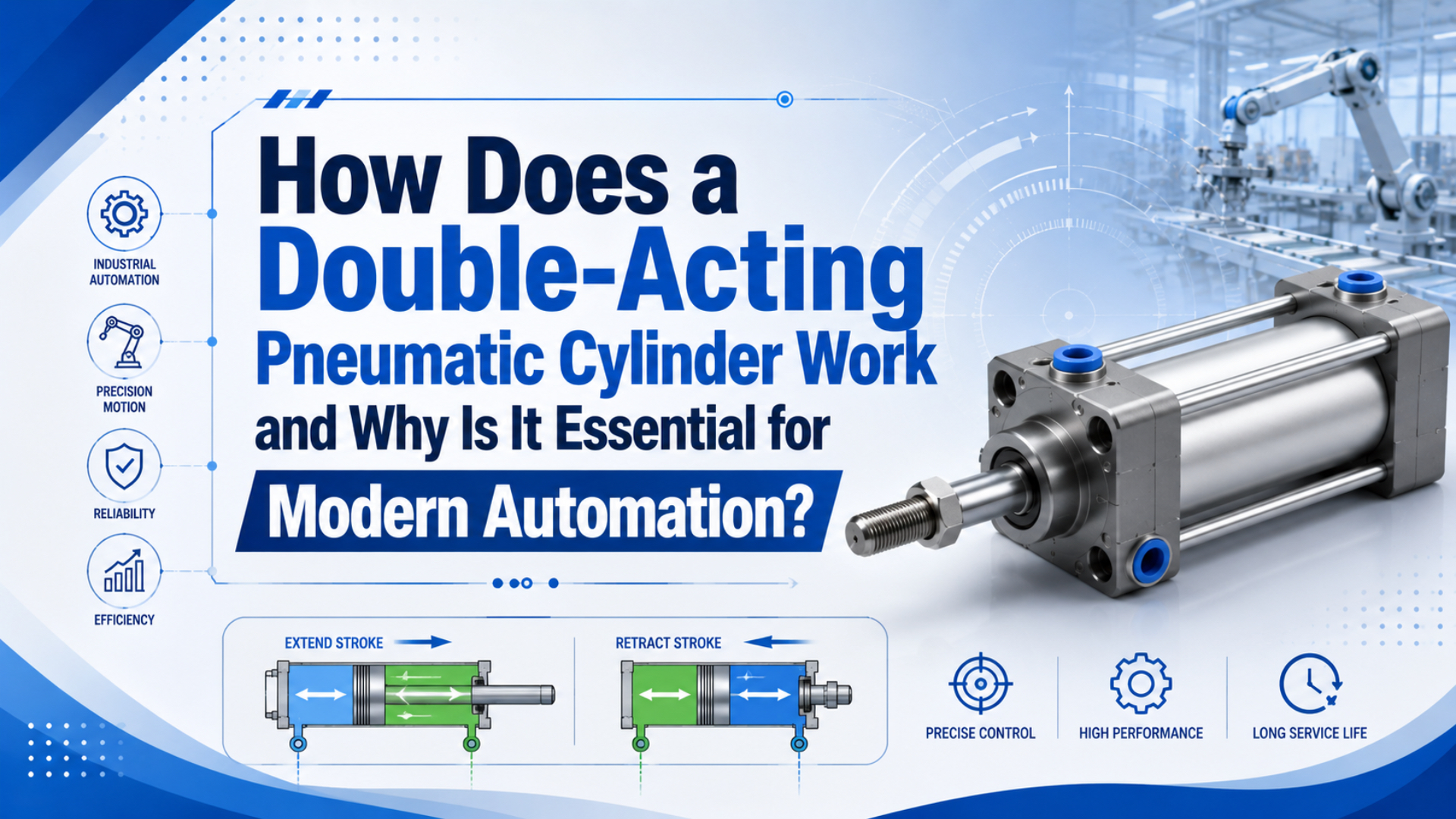
A double-acting pneumatic cylinder works by using compressed air on both sides of a piston. One port fills while the opposite port exhausts, then a directional valve reverses the flow for the return stroke. That gives powered extension and powered retraction, not just a spring or gravity return.
At 100 psi, a 2-inch bore cylinder has about 3.14 in2 of piston area and produces about 314 lbf of ideal extension force before friction, pressure drop, and back pressure (AutomationDirect Cylinder Sizing, 2026). That simple number explains why double-acting cylinders are still common in clamps, pushers, stops, lifters, transfer stations, and test fixtures.
Key Takeaways
- A double-acting cylinder has two working ports, so air can power both extension and retraction.
- At 100 psi, a 2-inch bore gives about 314 lbf ideal extension force before losses.
- Retraction force is lower on single-rod cylinders because rod area subtracts from piston area.
- Speed depends on airflow and exhaust restriction, not pressure alone.
- Check bore, rod, valve flow, tubing, cushioning, sensors, and point-of-use pressure before ordering.
What Makes a Cylinder Double-Acting?
A cylinder becomes double-acting when it has 2 working ports. AutomationDirect describes double-acting air cylinders as having a port at each end, with the piston moving forward and back as high-pressure air alternates between those ports (AutomationDirect Pneumatic Air Cylinders, 2026).
In a single-acting cylinder, compressed air powers one direction. A spring, gravity, or external load returns the piston. That can be fine for a light clamp, ejector, release pin, or fail-return motion, but it limits return force and makes speed control uneven.
In a double-acting cylinder, compressed air powers both directions. Extension and retraction each get a controlled fill path and a controlled exhaust path. That is the practical difference. You can push, pull, clamp, unclamp, lift, lower, index, reject, or return a mechanism under valve control.
The usual parts are familiar: barrel, piston, piston seal, rod, rod seal, wiper, end caps, ports, cushion screws, mounting hardware, and sometimes sensors. What changes is the air logic. Both chambers are active, and the machine designer must size both the supply side and the exhaust side.
The word “double-acting” does not mean both directions have identical usable force. It means both directions are powered. Force can still differ because a single-rod cylinder loses rod-side area during retraction, and speed can differ because the two chambers have different volumes.
For the broader cylinder overview, use the companion guide on how pneumatic cylinders work in automation. This article stays narrower: two-port operation, valve routing, force difference, and selection checks.
How Does the Valve Create Extension and Retraction?
A 5/2 directional valve creates extension and retraction by feeding one cylinder port while venting the other. Tameson lists 1 supply port, 2 cylinder ports, and 2 exhaust ports in this setup, which is why the valve can reverse the piston on command (Tameson Directional Control Valves, 2026).
During extension, the valve connects supply air to the cap-end chamber. The rod-end chamber exhausts through the valve and muffler. When the valve shifts, supply air goes to the rod-end chamber and the cap-end chamber exhausts. That reversed pressure differential retracts the rod.
That sounds simple. In our experience, most field problems come from the part of the circuit people do not draw carefully: exhaust. A small muffler, long tube, undersized fitting, or over-tight speed controller can hold back pressure in the chamber that is supposed to empty.
Use a 4/2 or 5/2 valve when the cylinder only needs two end states. Use a 5/3 valve when the machine needs a defined center condition, such as closed-center holding, pressure-center holding, or exhaust-center release. The choice depends on safety function, load behavior, and what should happen when power is removed.
For valve-related control work, the related article on proportional flow control valves in rodless cylinder systems is useful when speed must change through a PLC signal instead of a hand-adjusted speed controller.
Why Is Retraction Force Lower on a Single-Rod Cylinder?
Retraction force is lower on a single-rod double-acting cylinder because the rod occupies pressure-acting area. AutomationDirect’s sizing table lists a 2-inch bore area as 3.14 in2; at 100 psi, that is 314 lbf extending before losses, but the retract side must subtract rod area first (AutomationDirect Cylinder Sizing, 2026).
The extension side usually uses full piston area:
Extension force = pressure x piston areaThe retraction side on a single-rod cylinder uses annulus area:
Retraction force = pressure x (piston area - rod area)Here is a practical metric example:
1 bar = 0.1 N/mm2
6 bar = 0.6 N/mm2
63 mm bore piston area = pi x 63^2 / 4 = 3,117 mm2
20 mm rod area = pi x 20^2 / 4 = 314 mm2
Extension force = 0.6 x 3,117 = 1,870 N before losses
Retraction force = 0.6 x (3,117 - 314) = 1,682 N before losses
That is about a 10% drop in theoretical force from rod area alone. Friction, pressure drop, side load, exhaust back pressure, and acceleration reduce the usable force further. If the machine retracts a clamp against a spring or lifts during retract, do the retract calculation first.
When we review weak retraction complaints, the bore is often large enough. The missing detail is usually rod-side area, exhaust restriction, or a load direction that changed between extend and retract. The fix may be a larger bore, a different rod size, a better valve, or a circuit change.
For a deeper formula walkthrough, see what is the cylinder formula for pneumatic systems and the dedicated guide on pneumatic cylinder rod area.
Flow Control, Speed, and Cushioning Checks
Cylinder speed is mainly a flow problem once pressure can move the load. SMC states that force depends on pressure while cylinder speed depends on airflow, and gives s = 28.8q / A for speed in inches per second from SCFM and piston area (SMC Control Air Flow of Cylinders, 2026).
Pressure gets the load moving. Flow fills and empties the chamber fast enough to meet the cycle time. A machine can have enough static pressure and still move slowly because the valve, fittings, tubing, speed controller, or muffler cannot pass enough air during the stroke.
Meter-out speed control is often the safer first choice for pneumatic cylinders because it restricts exhaust and keeps back pressure on the moving piston. Meter-in can work in some cases, but with overrunning loads it may let the cylinder run ahead of the supplied air.
Use this quick control table before blaming the cylinder:
| Symptom | Likely Circuit Check | Why It Matters |
|---|---|---|
| Slow both ways | Supply pressure under motion, FRL, valve Cv, tube ID | Both chambers are starved or exhaust is restricted. |
| Fast extend, weak retract | Rod-side area, rod-end pressure, exhaust muffler | Retract area is smaller and back pressure hurts more. |
| Jerky motion | Side load, dry seals, poor guide support, unstable regulator | Friction changes faster than pressure can stabilize. |
| Hard end impact | Cushion setting, external stop, moving mass, stroke speed | End energy must be slowed before the piston reaches the cap. |
Cushioning is not decoration. It decides whether the piston reaches the end cap quietly or with repeated impact. Built-in pneumatic cushions help, but heavy tooling, high speed, short deceleration distance, and off-center loads may still need external shock absorbers or slower approach speed.
Need to connect flow, speed, and compressor demand? The article on how to calculate pneumatic flow rate is the better companion, because this page is focused on the double-acting cylinder cycle itself.
When Should You Choose Double-Acting Instead of Single-Acting?
Choose a double-acting cylinder when both directions need controlled force, speed, or timing. ISO 15552:2018 covers detachable-mounting pneumatic cylinders up to 1,000 kPa, or 10 bar, with bores from 32 mm to 320 mm, showing how broad standard double-rod and single-rod cylinder interchangeability has become (ISO 15552:2018, 2025).
Single-acting cylinders still have a place. They use fewer air lines, can be simpler to pipe, and can provide a spring-return behavior that is useful in release, eject, or fail-return functions. The tradeoff is weaker return behavior and less independent control.
Double-acting cylinders are the better fit when the machine must pull as confidently as it pushes. Examples include gates, stoppers, clamping jaws, transfer pushers, reject stations, door actuators, lift tables, indexing mechanisms, and fixtures that must return under load.
Use this selection split:
| Decision Point | Single-Acting Fit | Double-Acting Fit |
|---|---|---|
| Return force | Spring or gravity is enough. | Return must be powered. |
| Stroke length | Short strokes where spring return stays practical. | Longer strokes or repeatable two-way motion. |
| Speed control | One direction is the main controlled motion. | Both directions need separate speed settings. |
| Load direction | External load helps return. | Load can resist either direction. |
| Safety behavior | Spring return is the desired fail state. | Valve center condition and safety dump logic decide the fail state. |
Do not select double-acting only because it sounds stronger. Select it because the return stroke is part of the machine function. If the return stroke only resets a light mechanism, a single-acting cylinder may be simpler. If the return stroke moves product, tooling, or a safety-related member, double-acting control usually deserves the review time.
For pressure selection, use the companion guide on air cylinder working pressure. Pressure should be chosen from force, valve, tube, and catalog limits, not from compressor nameplate pressure alone.
Selection Checklist for a Double-Acting Cylinder RFQ
Before an RFQ, calculate force and verify the air path. AutomationDirect recommends 25% extra force; CAGI says well-designed air systems usually keep pressure drop below 10% (AutomationDirect Cylinder Sizing, 2026; CAGI Pressure Drop Technical Brief, 2026).
Give the supplier enough information to check the cylinder and the circuit together:
- Bore and stroke, or required load and available pressure.
- Push force and pull force, with load direction for each stroke.
- Rod diameter or cylinder series if the rod-side force matters.
- Stroke time target for extension and retraction.
- Working pressure measured near the valve or cylinder, not only compressor pressure.
- Valve type, valve size, tube length, tube ID, fittings, and muffler type.
- Mounting style, guide support, side load, and expected moment load.
- Cushion requirement, end-stop method, moving mass, and impact risk.
- Sensors, PLC timing, and required fail state.
- Air quality, temperature, washdown, dust, or chemical exposure.
Here is the shortest working method:
- Calculate extension force from full piston area.
- Calculate retraction force from piston area minus rod area.
- Add force margin for friction, pressure drop, and load variation.
- Check target stroke time against valve and tube flow.
- Check cushion energy or external stopping.
- Confirm the valve center condition and safety behavior.
- Send measured pressure, not guessed pressure.
If you already know the required load but not the bore, start with the cylinder bore size calculator. If the bore is known and you need push and pull force, use the tool card above.
FAQ About Double-Acting Pneumatic Cylinders
These FAQs focus on 100 psi force from piston area and 10% pressure drop in the air system. Use them with the formulas above, then confirm against cylinder and valve catalogs (AutomationDirect Cylinder Sizing, 2026; CAGI Pressure Drop Technical Brief, 2026).
What is the main difference between single-acting and double-acting pneumatic cylinders?
A single-acting cylinder uses air for one direction and a spring, gravity, or external load for return. A double-acting cylinder uses air for both extension and retraction. The difference is not only force. It is separate control of both stroke directions, including speed, timing, and return behavior.
How does a double-acting cylinder retract?
The directional valve sends supply air to the rod-end chamber and exhausts the cap-end chamber. Pressure on the rod side pushes the piston back. On a single-rod cylinder, retract force is lower because rod area subtracts from effective piston area.
Why is my double-acting cylinder weaker when retracting?
Retraction is weaker when rod-side effective area is smaller, point-of-use pressure drops during motion, or exhaust back pressure remains in the opposite chamber. Check the rod area calculation, tube and valve size, muffler restriction, speed controller setting, and pressure at the cylinder port while the cylinder moves.
Does higher pressure make a double-acting cylinder faster?
Higher pressure can help the cylinder overcome load and friction, but speed mainly depends on airflow and chamber volume. SMC separates force from pressure and speed from airflow. If the valve, tube, fitting, or muffler is too small, pressure alone will not fix the cycle time.
Which valve is normally used for a double-acting pneumatic cylinder?
A 4/2 or 5/2 directional valve is common for two-position extension and retraction. A 5/3 valve is used when the center state matters, such as holding pressure, blocking ports, or exhausting both cylinder chambers. The safest choice depends on the load and machine risk.
What information should I send for a double-acting cylinder quote?
Send bore, stroke, rod diameter if known, load in both directions, working pressure, stroke time, valve type, tube length, mounting style, side load, cushion needs, sensor needs, and fail-state requirement. Include measured point-of-use pressure if the machine already exists.
Sources
- AutomationDirect: Pneumatic Air Cylinders, single-acting and double-acting cylinder definitions. Retrieved 2026-06-04.
- AutomationDirect: Cylinder Sizing and Force, piston area table, force relation, and 25% force margin guidance. Retrieved 2026-06-04.
- NASA Glenn Research Center: Aerodynamic Force, pressure force equals pressure times area. Retrieved 2026-06-04.
- Tameson: Directional Control Valves in Pneumatic Systems, 5/2 valve connection for double-acting pneumatic cylinders. Retrieved 2026-06-04.
- SMC: Control Air Flow of Cylinders, cylinder speed as a function of airflow and piston area. Retrieved 2026-06-04.
- CAGI: Technical Brief on Pressure Drop, 10% pressure-drop guidance for compressed-air systems. Retrieved 2026-06-04.
- ISO 15552:2018, pneumatic cylinders with detachable mountings, 1,000 kPa series, bores from 32 mm to 320 mm, confirmed current in 2025. Retrieved 2026-06-04.
- AutomationDirect: What is a Pneumatic Cylinder?, pneumatic cylinder explainer video used for visual context. Retrieved 2026-06-04.