


An FRL unit is critical because it controls the condition and flowing pressure of the air supplied to every downstream valve, cylinder, gripper, and air tool on its branch. A failed actuator stops one motion. A restricted filter, unstable regulator, or incorrect lubrication policy can disturb the whole pneumatic station at once.
That doesn’t mean every machine needs a three-piece filter-regulator-lubricator. Many applications use an FR unit with no lubricator. The useful question is narrower: can the point-of-use air-preparation assembly deliver the required air quality, pressure, and peak flow during the real machine cycle?
Key Takeaways
- ISO 8573-1 classifies compressed-air purity by particles, water, and oil.
- CAGI says a well-designed system should stay within 10% total pressure drop.
- Diagnose the FRL under peak flow before replacing downstream components.
This article focuses on diagnosis, maintenance priority, and upgrade justification. For component definitions and general selection, use the broader FRL air-source treatment guide.
Why Can One FRL Affect the Whole Pneumatic Station?
One FRL can affect a whole station because ISO 8573-1 organizes compressed-air purity around three primary contaminant groups: particles, water, and oil. The local treatment assembly also sets downstream pressure, so a single restriction or control fault can change both air quality and actuator performance (ISO 8573-1, 2010).
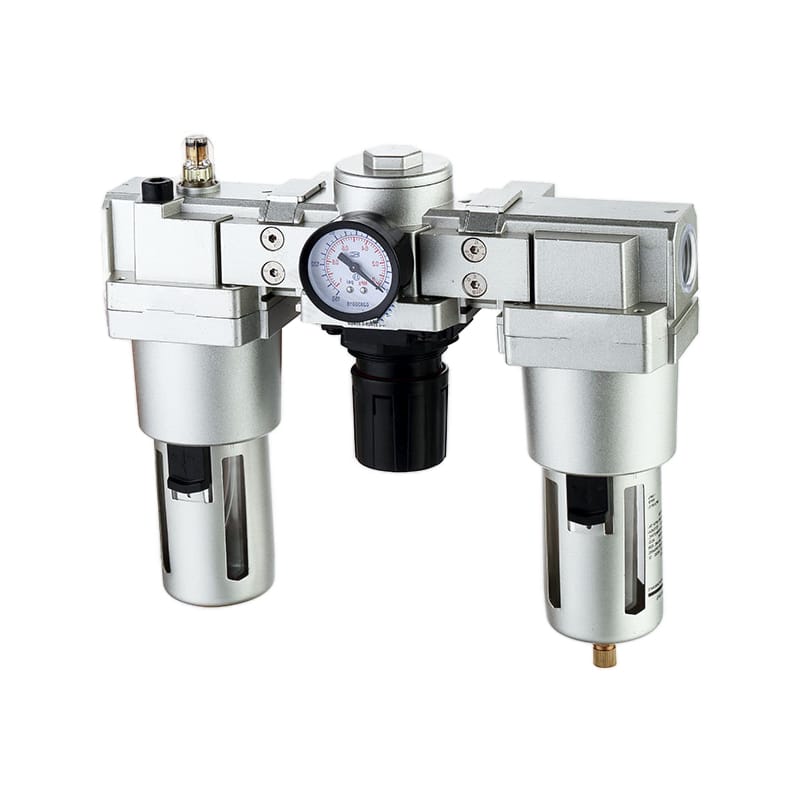
The filter catches specified particles and separates bulk liquid. The regulator reduces and controls pressure. A lubricator, when the application requires one, meters oil into the downstream air. These functions sit upstream of the machine’s valves and actuators, which gives the assembly a wide fault footprint.
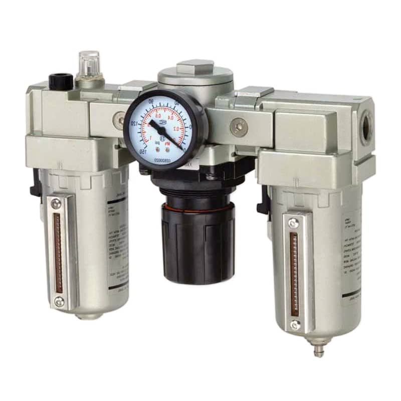
The FRL is not a substitute for the compressor-room dryer, main-line filters, correct pipe sizing, or drainage. It is the final local control point. If several downstream devices become slow, sticky, wet, or inconsistent at the same time, check their shared air path before assuming that several components failed independently.
The most useful diagnostic distinction is shared fault versus local fault. When every motion fed by one FRL changes together, inspect the shared filter, regulator, shut-off valve, fittings, and supply branch. When only one motion changes, move downstream to its valve, tubing, flow controls, actuator, load, and exhaust.
FRL Failure Modes That Deserve Immediate Attention
A loaded filter deserves immediate attention when differential pressure reaches 5-7 psig, the general replacement trigger in CAGI’s pressure-drop brief. A torn element can create the opposite symptom: differential pressure suddenly falls while contamination passes downstream, so a low reading alone doesn’t prove that the filter is healthy (CAGI, 2026).
| FRL fault | Evidence to collect | Likely downstream symptom | First action |
|---|---|---|---|
| Filter restriction | pressure before and after filter during peak flow | slow cylinders, regulator droop, long cycle time | compare differential pressure with supplier limit |
| Torn or bypassed element | sudden low differential pressure, dirt downstream | sticky spools, scored seals, blocked small orifices | isolate, inspect, and replace the element |
| Failed condensate drain | rising liquid level, water after the bowl | corrosion, erratic valves, cold-weather freezing | service drain and check dryer performance |
| Regulator undersizing | stable pressure at rest, large sag during flow | weak clamps, inconsistent speed | check flow curve, inlet pressure, and peak demand |
| Regulator creep | outlet pressure rises with no demand | excessive force, leakage, harsh end impact | inspect seat and relieving configuration |
| Wrong lubrication policy | unexpected oil or dry-wear evidence | contamination or accelerated tool wear | follow every downstream device manual |
Before opening an FRL bowl or removing a regulator, follow the site’s energy-control procedure. OSHA 29 CFR 1910.147 explicitly includes pneumatic energy and requires stored or residual energy to be relieved or otherwise rendered safe during covered servicing work (OSHA, 2026).
Don’t use a bypass as a routine production workaround. It may restore pressure while sending untreated air downstream. If continuity is essential, the bypass arrangement needs an engineered treatment path, isolation procedure, and acceptance checks rather than an open line around the failed component.
How Should You Diagnose an FRL Before Replacing a Cylinder or Valve?
CAGI says a well-designed compressed-air system should have no more than 10% pressure drop from compressor discharge to any point of use. For an FRL diagnosis, divide that total into measured segments and record pressure while the fault-producing machine cycle is running, not only at idle (CAGI, 2026).
Pressure drop is the loss of usable pressure between two points while air flows through restrictions. It is not the same as a leak, although a large leak can lower system pressure and increase the loss observed during a production cycle.
A static gauge can look normal because little air is moving. Once several cylinders extend or a blow-off circuit opens, flow rises and restrictions become visible as pressure loss. What should you measure? Use synchronized gauges or pressure sensors at the FRL inlet, FRL outlet, and critical actuator or valve inlet.
For example, if the inlet stays at 90 psig while the outlet falls from 85 to 72 psig during a clamp cycle, the large dynamic loss is concentrated across the FRL. For example, if both gauges fall by the same amount, the dominant restriction or capacity problem is probably upstream.
- Reproduce the fault under the normal production load.
- Record inlet and outlet pressure at rest.
- Record the same points during peak flow.
- Calculate FRL differential pressure during the event.
- Move the downstream gauge to isolate hose, valve, manifold, and fitting losses.
- Repeat after servicing, without changing several variables at once.
| Observation | What it suggests | Next check |
|---|---|---|
| Inlet and outlet both fall | upstream header, branch, storage, or simultaneous demand | measure farther upstream |
| Inlet holds, outlet falls | FRL restriction or regulator flow limitation | filter differential and regulator flow curve |
| FRL outlet holds, actuator inlet falls | downstream tubing, coupler, valve, or manifold restriction | move gauge through the circuit |
| Pressure holds, motion remains weak | load, seal friction, exhaust restriction, or mechanical binding | inspect actuator and mechanism |
Pressure diagnosis works best as a subtraction problem. Measure the loss across one segment at a time. Replacing a cylinder because the regulator gauge sags mixes cause and symptom, while segment measurements show where usable pressure is actually being lost.
Use the calculator below to estimate straight-run branch and fitting losses before comparing the estimate with measured FRL differential pressure. The calculator does not model the internal FRL element or regulator flow curve, so final selection still depends on manufacturer data and a live-cycle test.
For a deeper isolation sequence, see the pneumatic pressure-drop troubleshooting guide and the guide to pressure fluctuations during machine cycles.
What Can an FRL Fix, and What Requires a Dryer?
ISO 8573-1 separates particles, water, and oil into distinct purity classifications, so one nominal micron rating cannot define total air quality. A point-of-use filter can remove specified solids and bulk liquid, but a dryer is required when the application needs a controlled pressure dew point (ISO 8573-1, 2010).
Pressure dew point is the temperature at which water begins to condense at the stated compressed-air pressure. A clear filter bowl at the time of inspection doesn’t prove that water vapor will remain gaseous at the coldest downstream location.
| Requirement | FRL contribution | What may still be required |
|---|---|---|
| Remove pipe scale and larger particles | particulate filter | finer staged filtration for tighter classes |
| Separate collected liquid water | bowl and drain | correctly sized dryer for water vapor control |
| Reduce oil aerosol | coalescing stage where specified | activated carbon or process-specific treatment for oil vapor |
| Set machine pressure | regulator | adequate upstream pressure and branch flow capacity |
| Prevent restart surge | optional soft-start and dump module | machine-specific safety design and validation |
Festo describes standard filter-regulator filtration levels of 40 and 5 micrometers, and notes that finer filtration should be staged to avoid rapid loading and excessive pressure drop (Festo, 2026). A finer element is not automatically a better element if the application doesn’t need it.
If liquid repeatedly appears in the local bowl, treat that as evidence, not proof that the bowl is undersized. Check dryer outlet dew point, drain function, pipe temperature, drop-leg layout, and seasonal conditions. The pressure dew point guide explains why vapor control must be matched to the coldest part of the system.
For oil aerosol and fine-particle control, compare the application requirement with the coalescing-filter guide. Avoid claiming an ISO class until the complete treatment train and measurement point have been defined.
Does Every Pneumatic System Need a Lubricator?
No. Festo’s modular service-unit range lists at least eight possible functions, including filters, regulators, dryers, soft-start valves, sensors, and lubricators, which shows that air preparation should be assembled by application rather than treated as a fixed three-piece package (Festo, 2026).
The lubricator is justified when a downstream tool or component manual requires continuous oil mist. It may be inappropriate for factory-lubricated cylinders and valves, electronics, paint, food-contact processes, cleanrooms, or any exhaust path where oil contamination is unacceptable.
Check these points before adding or removing the lubricator:
- Do all downstream component manuals permit the same oil and delivery method?
- Has oil already been introduced into the branch?
- Can the oil reach the device at the actual flow and piping distance?
- Could exhaust oil contaminate the product, sensor, workplace, or process?
- Is the lubricator filled, adjusted, and inspected under a defined maintenance plan?
An existing lubricator that is always empty is not evidence that lubrication is unnecessary. It may indicate neglected maintenance or that the assembly was specified incorrectly. Verify the downstream equipment requirements before changing the circuit.
Which Maintenance Triggers Matter More Than the Calendar?
CAGI gives two general filter triggers: replace the element at 5-7 psig differential pressure or at least every six months. The component manufacturer’s limit and the site’s air-quality requirement remain controlling, and a differential-pressure indicator is a restriction indicator rather than a direct cleanliness measurement (CAGI, 2026).
A maintenance route should capture measurements, not just a check mark. Record the FRL inlet and outlet pressure during the fault cycle, bowl liquid level, drain operation, filter service date, regulator setpoint, and any evidence found downstream.
| Check | Trigger | Corrective response |
|---|---|---|
| Filter differential pressure | supplier limit or CAGI’s 5-7 psig general trigger | replace element and investigate contamination load |
| Differential pressure suddenly decreases | possible torn or bypassed element | inspect element and downstream cleanliness |
| Liquid repeatedly reaches warning level | drain fault or excessive upstream moisture | service drain, verify dryer and piping |
| Regulator pressure sags under flow | capacity or inlet-pressure problem | review peak flow and regulator curve |
| Outlet pressure creeps at zero flow | regulator seat leakage | isolate and repair or replace regulator |
| Lubricator consumption changes | empty bowl, blockage, or changed flow | confirm oil type, rate, and application need |
What if the same cylinder seal keeps failing? Keep the failed part and inspect its wear pattern. Scoring, corrosion, swelling, and dry abrasion point to different causes. Use the industrial cylinder seal guide to connect the damage evidence with air quality, lubricant compatibility, alignment, and load.
Building a Defensible FRL Upgrade Case
For systems near 100 psig, the DOE sourcebook estimates that every 2 psi increase in compressor discharge pressure raises full-flow energy use by about 1%. That makes measured pressure loss more useful than a generic claim that a premium FRL will always save a fixed dollar amount (U.S. Department of Energy, 2003).
Build the proposal from the site’s own baseline. Measure the loss, identify the affected production event, and compare repair, replacement, and redesign options. A universal FRL payback figure is not credible because energy price, flow, duty cycle, downtime cost, spare-parts policy, and failure frequency vary by plant.
A strong FRL business case separates avoided loss from energy savings. Avoided loss covers verified downtime, scrap, labor, and damaged components. Energy savings covers measured reductions in pressure, flow, leakage, or compressor power. Keeping those columns separate prevents the same benefit from being counted twice.
| Business-case input | Evidence source | Annual value method |
|---|---|---|
| FRL-related downtime | CMMS work orders and line records | hours x verified contribution margin or downtime rate |
| Replacement parts | purchase history tied to confirmed causes | annual FRL-related parts spend |
| Maintenance labor | work-order hours | hours x loaded labor rate |
| Scrap or rework | quality records linked to pressure or contamination | affected units x verified cost per unit |
| Compressor energy | measured flow, pressure, power, and duty | site energy model or metered comparison |
| Project cost | supplier quotation and installation plan | hardware + labor + commissioning + spares |
Use simple payback = installed project cost / verified annual savings, but show the assumptions and sensitivity range. If the proposal depends on fewer failures, define how the team will confirm FRL causation after installation.
Before requesting a quotation, provide inlet-pressure range, required outlet pressure, peak flow and duty cycle, acceptable pressure drop, ISO 8573-1 target at the stated measurement point, port and tube sizes, drain preference, bowl material, ambient conditions, lubrication policy, and any safety functions. That data is more useful than asking for a “heavy-duty FRL.”
FAQs About FRL Unit Reliability
Two CAGI reference points answer many FRL questions: no more than 10% total system pressure drop in a well-designed system, and 5-7 psig as a general filter differential-pressure replacement trigger. Machine requirements and manufacturer limits can be tighter, so measurements must be interpreted in context (CAGI, 2026).
Is the FRL always the cause when several cylinders slow down?
No. A shared symptom makes the FRL and its supply branch strong suspects, but the header, receiver, compressor controls, simultaneous demand, or common exhaust restriction may also be responsible. Measure inlet and outlet pressure during the event. CAGI’s 10% system guideline helps frame the total loss, not identify one component automatically.
Can I select an FRL by matching the port size?
No. Port size does not establish flow capacity, regulator droop, filter differential pressure, drain behavior, or air-quality performance. Festo notes that undersizing air-preparation equipment can cause pressure fluctuations and reduce filter service life. Use peak flow, pressure curves, filtration requirements, and the actual machine cycle before confirming a size.
Will a finer filter always protect the system better?
No. Festo lists common 40 and 5 micrometer stages and recommends staged filtration when tighter cleanliness is required. An unnecessarily fine element can load faster and add pressure drop. Start with the ISO 8573-1 requirement at the point of use, then select the treatment stages that meet it efficiently.
Can an FRL remove all water from compressed air?
No. A filter bowl can separate bulk liquid, but water vapor control requires a dryer selected for the required pressure dew point. ISO 8573-1 treats water as its own purity category. Repeated liquid at the machine should trigger checks of the dryer, drains, pipe temperature, and distribution layout.
Is it safe to replace an FRL while the rest of the plant remains pressurized?
Only when an engineered isolation arrangement and the site’s energy-control procedure make the work safe. OSHA 1910.147 covers pneumatic energy during servicing and requires hazardous stored energy to be relieved or rendered safe. Closing a control valve or pressing an emergency stop may not isolate residual pressure by itself.
Sources and Retrieval Notes
- ISO 8573-1:2010, Compressed air, contaminants and purity classes. Current published edition confirmed on the ISO page. Retrieved 2026-07-14.
- CAGI, Technical Brief on Pressure Drop. Retrieved 2026-07-14.
- CAGI, Working With Compressed Air. Retrieved 2026-07-14.
- U.S. Department of Energy, Improving Compressed Air System Performance. Retrieved 2026-07-14.
- OSHA 29 CFR 1910.147, Control of Hazardous Energy. Retrieved 2026-07-14.
- Festo, How Does an Air Preparation Unit Work?. Retrieved 2026-07-14.
- Festo, Compressed Air Service Units. Retrieved 2026-07-14.
- AutomationDirect, Air Prep Basics. Retrieved 2026-07-14.