

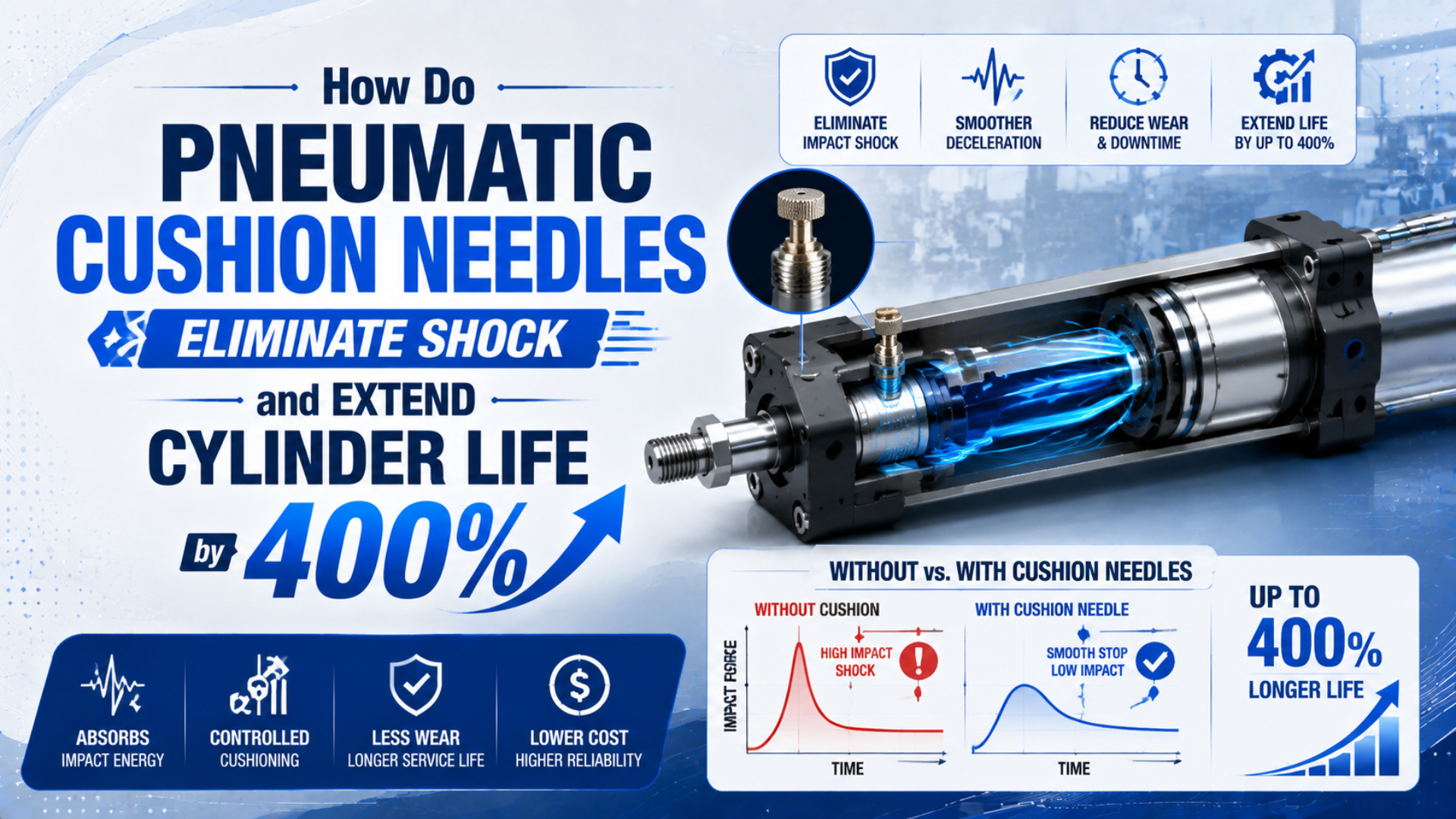
Pneumatic cushion needles are adjustable restrictions that control how quickly trapped air leaves a cylinder’s end-cushion chamber. The resulting back pressure slows the piston before it reaches the end cap, reducing repeated impact on seals, piston hardware, mounts, sensors, and the machine frame.
Can correct adjustment extend service life by 400%? It can produce a large application-specific improvement when hard end impacts were the dominant failure cause. It cannot guarantee a fourfold result. Service life still depends on moving mass, cushion-entry speed, side load, alignment, pressure, air quality, cycle rate, and the cylinder manufacturer’s cushion limit.
Key Takeaways
- Parker warns that cushion-entry speed can be about 50% above average stroke speed.
- The cushion spear traps air; the needle adjusts the bypass flow.
- Use the exact product manual because fully open, fully closed, and adjustment limits differ by series.
- Bounce means more restriction is not always the answer.
- Compare calculated energy with the manufacturer’s cushion chart before tuning.
What Does the Cushion Needle Actually Adjust?
Festo describes 3 common end-cushioning methods: elastic, pneumatic or servo-pneumatic, and hydraulic. In adjustable pneumatic cushioning, a defined air volume is trapped near the end position and an adjustment screw controls its exhaust (Festo, 2022). The needle therefore controls bypass flow, not piston position.
A typical cushioned cylinder contains a cushion boss, spear, or sleeve on the piston assembly. As the piston approaches the end cap, that part enters a matching cushion seal or bore and closes the normal exhaust path. Air remaining in the end chamber must then leave through the smaller adjustable passage.
The cushion needle changes that passage. Turning it toward greater restriction reduces exhaust flow, raises chamber back pressure, and usually increases deceleration. Turning it toward a more open position lets trapped air escape faster and reduces the damping effect.
The check path has a separate job. It allows freer airflow when the piston starts its next stroke, so the cylinder doesn’t have to fill the cushion chamber through the restricted needle passage. Contamination or damage in that check path can make one stroke leave the end position slowly even when the cushion needle looks correctly set.
The distinction is practical: the moving cushion spear determines when the main exhaust closes, while the stationary needle determines how fast the trapped air bleeds away. Calling both parts the “cushion needle” hides two different failure modes.
For the broader component-level explanation, see how pneumatic cylinder cushioning prevents damage and noise. The rest of this article concentrates on commissioning and fault diagnosis.
Pre-Adjustment Data: Mass, Speed, Pressure, and Cushion Stroke
Parker states that piston speed at the start of cushioning is typically about 50% higher than average speed, and that this higher value should determine cylinder selection (Parker, 2025). Record the load and real approach speed before touching the cushion needle, because adjustment cannot repair an overloaded cushion.
Collect these values for both extension and retraction:
| Input | Unit | Why it changes the result |
|---|---|---|
| Moving mass | kg | Includes piston, rod, carriage, tooling, product, brackets, and moving guide parts |
| Cushion-entry speed | m/s or mm/s | Kinetic energy rises with velocity squared |
| Working pressure during motion | bar, MPa, or psi | Determines the continuing drive force during deceleration |
| Cushion stroke | mm | Sets the distance available to slow the piston |
| Mounting orientation | horizontal, vertical, or inclined | Changes the gravity component and load direction |
| Cycle rate | cycles/min | Repeated energy affects temperature and component life |
| External force | N | Springs, contact forces, or gravity may add to the stopping load |
| Manufacturer cushion limit | J or mass-speed curve | Defines the approved operating envelope |
Average speed is stroke length divided by travel time, but it can hide acceleration within the stroke. Measure the approach region when possible. Parker’s 50% warning is a conservative screening clue for the cited product family, not a universal conversion factor for every cylinder.
Check the circuit too. Valve capacity, tube inside diameter, fitting restrictions, muffler condition, meter-out setting, and point-of-use pressure all affect approach speed and trapped pressure. A cushion screw should not be used to conceal an undersized valve or blocked exhaust.
When the speed problem exists through the whole stroke, review meter-out speed control before adjusting the final few millimetres. The speed controller shapes the stroke; the cushion needle shapes only the end zone.
How Should You Adjust a Cushion Needle Safely?
SMC manuals show why one universal “turn it a quarter turn” procedure is unsafe. One CHN-series manual warns against running with the needle fully closed and recommends no more than 2 turns open as a guideline, while another series starts adjustment from the closed reference and opens gradually (SMC, 2024; SMC, 2025).
Always use the exact manual for the installed cylinder. Record the starting position before moving anything, and never force the screw against its seat or beyond its retention range. Some needles can be damaged, leak, or eject if backed out beyond the permitted limit.
Use this controlled sequence:
- Isolate access to the moving load and confirm the machine can be tested safely.
- Verify the cylinder model, cushion type, screw direction, and allowed adjustment range.
- Inspect alignment, mounts, rod, guide, muffler, tubing, valve, and speed controller.
- Reduce cylinder speed and pressure to the safe commissioning values allowed by the manual.
- Begin from the manufacturer’s initial or reference position, not an invented number of turns.
- Cycle the real load through one direction and observe impact, rebound, final travel, and sensor timing.
- Change the needle in small increments, then repeat several cycles before making another change.
- Increase speed toward the production setting only after the stop remains controlled.
- Tune the opposite direction separately because load, piston area, and exhaust path can differ.
- Record the final position, pressure, stroke time, payload, and observed end-stop behaviour.
The target is a clean stop without a metallic hit, visible rebound, or a long crawl into the end sensor. Closing the needle harder is not automatically safer. Excess trapped pressure can make the piston bounce or delay the final position.
What if the impact remains after the useful adjustment range is exhausted? Stop tuning. Recheck mass and entry speed against the catalogue, then reduce speed or choose a cylinder, motion profile, or shock absorber with sufficient capacity.
Troubleshooting Impact, Bounce, and Slow Final Travel
Festo says PPV adjustment depends on mass, speed at the moment of damping, desired deceleration, working pressure, and cylinder resistance (Festo, 2022). Those 5 variables explain why the same needle position can produce impact with one payload and rebound or slow travel with another.
| Symptom | Likely condition | First checks | Avoid this response |
|---|---|---|---|
| Sharp metallic hit | Too little damping, excessive entry speed, worn cushion seal, or overloaded cushion | Mass, speed, screw position, cushion sleeve, cap marks | Closing the needle without checking the catalogue limit |
| Rebound from the end | Too much trapped pressure, high approach energy, elastic load, or loose structure | Needle restriction, guide stiffness, speed, payload | Assuming more damping always prevents bounce |
| Slow final travel | Needle too restrictive, blocked muffler, low dynamic pressure, or sticky check path | Exhaust path, pressure during motion, screw position | Raising plant pressure to force the piston home |
| One direction behaves differently | Gravity, unequal piston areas, different speed-control paths, or asymmetric tooling | Extend and retract data separately | Copying one end’s screw setting to the other |
| Sensor changes state late | Long cushion crawl, sensor position, magnetic margin, or PLC timing | Actual final speed and sensor location | Moving the sensor before correcting motion |
| Setting repeatedly changes | Loose locking feature, vibration, contamination, damaged threads, or maintenance disturbance | Needle retention and maintenance records | Adding thread sealant unless the manufacturer permits it |
The sound alone does not identify the fault. A metal knock points toward end impact. A sustained hiss points toward exhaust flow. Scraping suggests alignment or guide damage. Recording sound, pressure, position, and direction together prevents the needle from becoming the default suspect for every cylinder problem.
If the whole stroke is slow or inconsistent, check compressed-air pressure-drop causes. Cushion adjustment only affects the final zone after the cushion spear closes the main exhaust path.
How Much Energy Must the Cushion Absorb?
Parker’s cushion charts use moving mass and maximum permissible speed at the start of cushioning, while its documentation directs users to additional shock absorbers when those limits are exceeded (Parker, 2025). Calculate kinetic energy as a screening input, then compare the application with the exact manufacturer’s chart.
The moving system’s kinetic energy at cushion entry is:
Where:
- is kinetic energy in joules.
- is total moving mass in kilograms.
- is measured or conservatively estimated cushion-entry speed in metres per second.
Speed deserves special attention. If the entry speed rises from to ${1.5}v_c$, kinetic energy becomes:
That 2.25 ratio is a direct consequence of the velocity-squared relationship. It explains why sizing from average stroke speed can materially understate cushion demand when entry speed is 50% higher. It does not mean every cylinder actually follows a 1.5 speed ratio; use measured motion or the exact catalogue method.
The cylinder may continue producing drive force during the cushion stroke. A simplified screening term for that work is:
Here, is drive work in joules, is the net force that continues pushing in the direction of travel in newtons, and is cushion stroke in metres. Gravity, friction, opposite-chamber pressure, and external process forces affect the net value.
Some manufacturers combine kinetic and drive contributions differently or publish a mass-speed curve instead of an energy value. Follow that method. Do not substitute the equations above for a product limit, cyclic thermal rating, or application validation.
The calculator is a screening tool. It cannot know cushion-seal condition, needle geometry, compressible-flow behaviour, side load, structural flexibility, or the manufacturer’s permitted cycle rate.
When Is the Built-In Cushion Too Small?
Parker bases cited OSP-P load data on speeds up to 0.5 m/s and says additional shock absorbers are required when maximum permissible cushion values are exceeded (Parker, 2025). A built-in air cushion is therefore a catalogue-limited stopping device, not a universal absorber for every moving load.
Stop adjusting and review another solution when:
- Moving mass and entry speed fall outside the manufacturer’s cushion chart.
- The needle reaches its useful range while impact or rebound remains.
- Gravity accelerates a vertical load into the end position.
- Tooling or an overhung carriage introduces damaging moments into the guide.
- Cycle frequency causes heat or performance drift.
- The machine needs a repeatable stopping position that air compressibility cannot provide.
- A hard process stop must absorb tooling energy outside the cylinder’s centreline.
- Payload changes are too large for one manual setting.
An external hydraulic shock absorber can carry more stopping energy and may provide a more predictable deceleration stroke. Place it close to the load path and centre of gravity where possible. Otherwise, the cylinder may stop quietly while the frame or guide continues to see a damaging moment.
Self-adjusting or servo-pneumatic cushioning can help where payload or speed changes. They still have operating envelopes. The high-speed cylinder air-cushion guide covers velocity-sensitive sizing and external absorber boundaries in more detail.
Review the whole actuator before increasing speed. The high-speed cylinder specification checklist connects cushioning with valve flow, rod load, guidance, sensors, mounts, and duty cycle.
Maintenance and RFQ Records
Festo recommends checking and readjusting PPV cushioning during service when necessary, while its self-adjusting PPS design removes the manual screw and adapts within its stated load and speed range (Festo, 2022). Maintenance frequency should follow measured drift, duty, environment, risk, and the exact manual rather than a universal monthly schedule.
Record the following after commissioning:
- Cylinder manufacturer, series, bore, stroke, cushion type, and serial or revision data
- Cushion screw position or documented reference setting for each stroke direction
- Moving mass and tooling configuration
- Extend and retract time at production load
- Cushion-entry speed when measured
- Pressure at the cylinder during motion
- Valve, speed-controller, fitting, tube, and muffler part numbers
- Mounting orientation, guide arrangement, and external stops
- Impact, bounce, final-position, noise, and sensor observations
- Adjustment date, technician, reason, and acceptance result
Inspect for impact marks, loosened mounts, damaged cushion sleeves, contaminated passages, leaking seals, bent rods, worn guides, and changing sensor timing. Do not compensate for mechanical damage by repeatedly closing the needle.
A replacement RFQ needs more than bore and stroke. Send photos of the end caps and cushion screws, measured motion data, payload, pressure, orientation, port and tube sizes, valve model, failure symptoms, and the existing cylinder code. State whether the target is a softer stop, shorter cycle, higher speed, heavier payload, or improved sensor repeatability.
Cushion Needle FAQs: What Should Technicians Check?
These 5 questions use Parker’s 50% cushion-entry-speed warning and Festo’s 3 cushioning-method categories as practical commissioning boundaries (Parker, 2025; Festo, 2022). The correct setting still comes from the exact cylinder manual, measured moving load, actual approach speed, and published catalogue cushion limit.
Should I start with the cushion needle fully open or fully closed?
Use the exact manufacturer’s procedure. SMC instructions differ by product family: some use a closed reference before gradual opening, while another manual warns not to operate fully closed. Record the initial position, stay inside the specified adjustment range, test at safe speed, and never force the needle against its seat.
Why does the piston bounce after I close the needle?
Closing the needle traps more air and raises back pressure. Excess restriction can act like a pneumatic spring, decelerating the piston and then pushing it away from the end. Reopen the needle in permitted increments, reduce approach speed, and check load elasticity, guide stiffness, dynamic pressure, and the product’s cushion envelope.
Can cushion adjustment compensate for an oversized moving load?
No. Adjustment changes the rate at which trapped air escapes; it does not increase the cylinder’s published cushion capacity without limit. Calculate moving energy, include continuing drive work where required, and compare mass and entry speed with the catalogue. Reduce speed or add an appropriately sized external absorber when the limit is exceeded.
Why do extension and retraction need different settings?
The piston areas, drive forces, gravity direction, external load, speed-control paths, and exhaust volumes can differ between extension and retraction. Tune and record each end separately under the real payload. Matching screw positions do not prove matching deceleration, especially on vertical cylinders or machines with asymmetric tooling.
Does correct cushioning guarantee four times longer cylinder life?
No. Removing repeated end-cap impact can substantially extend life when impact was the dominant failure mode, but a universal 400% guarantee is not technically defensible. Side load, contamination, inadequate lubrication, corrosion, pressure spikes, misalignment, duty cycle, seal material, and maintenance practices can still determine when the cylinder fails.