

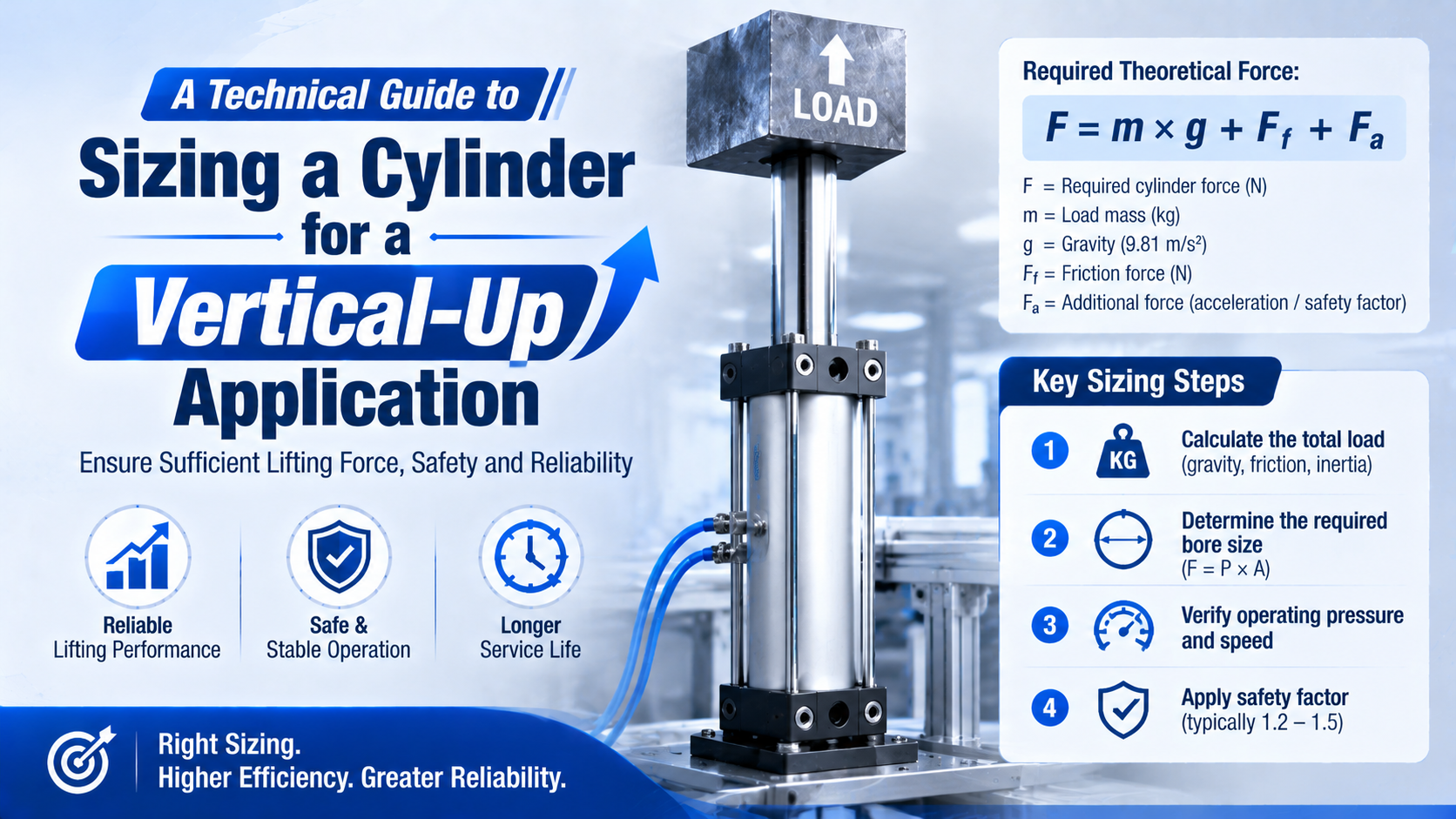
Vertical-up cylinder sizing starts with the mass that must rise, the required upward acceleration, measured resistance, and the lowest pressure available at the actuator. It then checks which chamber performs the lift and converts the design force into a minimum effective area and standard bore. Gravity is only one term in the calculation.
This article is a calculation worksheet. It does not select guarding, external guidance, a rod lock, a brake, or a maintenance support. Those system decisions belong in the broader vertical lifting cylinder selection guide.
Key Takeaways
- Standard gravitational acceleration is 9.80665 m/s² according to NIST.
- Add required upward acceleration and measured resistance instead of applying a universal dynamic percentage.
- Size from minimum drive-port pressure, opposing-port backpressure, and the correct piston area.
- A calculated bore does not provide positive load holding after air loss.
Publisher information is available on the About Us page. Send technical questions or correction requests through Contact.
What Inputs Define a Vertical-Up Sizing Case?
ISO 4414:2010 remains current after its 2021 review and covers general rules and safety requirements for pneumatic systems. It does not prescribe one bore, working pressure, or design factor for every lift. Define the maximum moving mass, motion profile, port pressures, geometry, and fault boundaries before calculating area (ISO 4414, accessed 2026).
Moving mass is every component whose centre of gravity rises with the cylinder stroke. Count the payload, tooling, fixture, carriage, moving rod or carrier, hose chain, and any moving portion of a mechanism. Don’t add the stationary cylinder body just because it is part of the assembly.
The minimum calculation sheet needs these inputs:
| Input | Symbol | Required value |
|---|---|---|
| Maximum moving mass | kg, including payload and moving hardware | |
| Upward acceleration | m/s² from the motion profile | |
| Guide and process resistance | N, measured or conservatively documented | |
| Project design factor | Defined by the application standard or risk review | |
| Lift direction | extension or retraction | Identifies full piston area or annular area |
| Minimum drive-port pressure | Pa, bar, or MPa at the cylinder during motion | |
| Maximum opposing-port pressure | Same unit as drive pressure | |
| Candidate rod diameter | Needed when the annular area affects force | |
| Stroke and mounting | geometry | Needed for buckling, alignment, and clearance checks |
Why use port pressure rather than regulator set pressure? The cylinder sees the pressure remaining after supply-line, valve, fitting, and flow losses. The exhausting chamber can also retain backpressure. Record both under the worst permitted production demand.
In our experience, the fastest way to expose a weak vertical-up calculation is to ask for four values on one drawing: maximum mass, required acceleration, minimum drive-port pressure, and maximum opposing-port pressure. If one is missing, a precise-looking bore result is still built on an assumption.
Calculate the Upward Force Demand From Mass and Acceleration
NIST gives standard acceleration of gravity as 9.80665 m/s². A 100 kg mass therefore creates 980.665 N of gravitational force before acceleration, guide friction, or process resistance is added. Calculate the stated motion rather than replacing acceleration with a fixed 20% or 30% allowance (NIST Guide for the Use of the International System of Units, accessed 2026).
For an upward move, the basic mechanical demand is:
Here, is the required upward mechanical force in newtons, is moving mass in kilograms, is gravitational acceleration, is required upward acceleration, and combines guide friction and external process resistance in newtons.
If the project requires a documented design factor, apply it openly:
The factor is not a universal pneumatic constant. It may cover specified load variation, measurement uncertainty, wear allowance, or a company design rule. Don’t use it to conceal unknown mass, acceleration, or pressure. Determine those inputs first.
Avoid double counting. If a measured resistance value already includes guide friction and tooling force, don’t add another generic friction percentage to the demand. Likewise, an acceleration term of already increases the mass-related force by 30%; multiplying by a second “dynamic factor” for the same acceleration counts it twice.
The cleanest worksheet keeps three layers separate: physics demand, project design factor, and candidate-cylinder capability. This makes every assumption visible and lets a reviewer change one input without rebuilding the entire calculation.
Choose the Lift Chamber and Effective Pressure
Parker states that theoretical cylinder force follows and publishes separate push and pull values because the piston rod reduces retraction area. The same distinction controls vertical-up sizing: extension normally uses full piston area, while retraction uses the smaller annular area (Parker Pneumatic Actuator Products, 2025).
For bore diameter and rod diameter :
Here, is full piston area and is annular area. Use consistent SI units: diameters in metres produce area in square metres, pressure in pascals, and force in newtons.
If extension lifts the load, pressure acts on the full piston area while rod-side backpressure opposes motion:
If retraction lifts the load, rod-side pressure acts on annular area while cap-side pressure opposes motion:
represents cylinder-internal and connection losses not already included in the mechanical demand. Obtain it from manufacturer data, measured performance, or a documented conservative allowance. Don’t subtract the same loss in both sides of the comparison.
Retraction lifting can require a larger bore because is smaller than . It can also change rod buckling, contamination exposure, mounting, and fault behaviour. Select the physical orientation before finalizing the force calculation.
Convert Design Force Into a Minimum Bore
Parker’s OSP-P data gives theoretical forces of 1,178 N, 1,870 N, and 3,016 N at 6 bar for 50, 63, and 80 mm bores. Those values follow pressure multiplied by area and show why a decimal-place error can oversize or undersize a vertical axis by a factor of ten (Parker OSP-P Technical Data, 2025).
For a first-pass extension calculation, combine drive pressure and backpressure into a conservative effective pressure only when that simplification matches the circuit:
Then estimate the required area:
is the minimum effective area before selecting a catalogue cylinder. is the corresponding theoretical bore. Move to the next available standard bore, then repeat the calculation with the actual rod diameter, chamber areas, port pressures, and documented loss allowance.
The calculator is a screening tool. Its single working-pressure input cannot model every two-chamber pressure condition. When measured backpressure matters, enter an appropriately conservative effective pressure and confirm the result with the full chamber-force equations above.
Worked Example: Sizing a 120 kg Vertical-Up Load
Using NIST’s 9.80665 m/s² gravity value, a 120 kg assembly accelerating upward at 0.8 m/s² produces 1,272.8 N from mass and acceleration alone. Adding 150 N of documented guide and process resistance gives 1,422.8 N before the project’s stated design factor (NIST, accessed 2026).
Assume the following design inputs:
| Input | Value |
|---|---|
| Maximum moving mass | 120 kg |
| Required upward acceleration | 0.8 m/s² |
| Guide and process resistance | 150 N |
| Project design factor | 1.25 |
| Lift direction | extension |
| Minimum cap-end pressure during motion | 0.55 MPa |
| Maximum rod-end backpressure | 0.05 MPa |
| Candidate rod diameter | 25 mm |
| Candidate internal-loss allowance | 10% of pressure force |
First calculate mechanical demand:
Apply the project-defined factor:
For preliminary bore estimation, use an effective pressure of 0.50 MPa:
The theoretical minimum is 67.3 mm, so the preliminary standard choice is 80 mm rather than 63 mm. Now verify the 80 mm candidate using its actual 25 mm rod and both port pressures:
With the example’s 10% internal-loss allowance:
The example candidate supplies about 2,284 N against a design demand of 1,778.5 N under the stated assumptions. That is a force-screening pass, not final approval. Replace the 10% illustration and both port pressures with configured manufacturer data or measured values before release.
What if the cylinder lifts on retraction? Repeat the calculation with the annular area as the driven area. Do not reuse the extension result.
Check the Selected Bore Against the Real Cylinder
SMC’s air-cylinder selection data calculates different maximum strokes for 0.3, 0.5, and 0.7 MPa operating pressures and for foot, flange, clevis, and trunnion mounting conditions. This confirms that bore force alone cannot approve a long compression stroke; rod diameter, pressure, stroke, and mounting change the buckling boundary (SMC Air Cylinders Model Selection, 2026).
After choosing a standard bore, check the configured product rather than a generic size:
-
Verify theoretical and usable extension and retraction force at the actual port pressures.
-
Confirm the manufacturer’s permitted pressure, speed, stroke, mounting, orientation, and temperature range.
-
Check piston-rod buckling when the rod pushes upward in compression. Use the rod buckling calculator for screening, then follow the selected manufacturer’s chart.
-
Check guide loads and overturning moments separately. A standard piston rod should not be treated as the payload’s linear guide.
-
Calculate flow, valve capacity, tubing loss, and exhaust restriction at the required lift speed. A larger bore raises air demand.
-
Verify moving mass and velocity against cushion or external shock-absorber energy limits.
-
Check brackets, pins, fasteners, frame stiffness, alignment, and full-stroke clearance.
For a separate push-and-pull check after the bore is known, use the pneumatic cylinder force calculator. Keep the input pressure consistent with the measured or calculated pressure at the actuator, not compressor nameplate pressure.
From our work, an 80 mm selection is not a result until it has a complete suffix: rod diameter, stroke, mounting, pressure range, speed, cushioning, seals, sensor arrangement, and holding strategy. The bore answers one question. The configured cylinder answers the application.
What This Calculation Does Not Prove
ISO 13849-1:2023 addresses safety-related control-system design, while OSHA 29 CFR 1910.147 addresses hazardous-energy control during covered servicing. Neither standard says that a correctly sized pneumatic bore will hold a suspended load after air loss. Treat motion, holding, emergency stopping, guarding, and maintenance support as separate functions (ISO 13849-1; OSHA).
The worksheet does not prove:
- that a closed-centre valve provides positive load holding;
- that a pilot-operated check valve covers every tube, seal, valve, or structural failure;
- that a rod lock can brake a moving load rather than hold a stopped one;
- that the guide can carry the applied side load and moments;
- that the cushion can absorb the moving assembly’s kinetic energy;
- that the machine reaches its required safety performance level;
- that a raised load is safe during maintenance.
Use the complete vertical lifting selection guide for configuration, guidance, speed control, end-of-stroke energy, loss-of-air behaviour, commissioning, and maintenance isolation. Use the cylinder rod-lock guide when a mechanical holding device is under review.
Can the axis still move when a tube ruptures, a seal leaks, power disappears, or someone services the machine? A bore calculation cannot answer that. The risk assessment and validated machine architecture must.
Vertical-Up Cylinder Sizing FAQs
NIST specifies standard gravity as 9.80665 m/s², and Parker’s 6 bar data lists only 1,178 N for a 50 mm bore rather than 11,780 N. These two values catch common vertical-up errors: confusing kilograms with newtons and shifting the pressure-area calculation by one decimal place (NIST; Parker).
Should gravity and upward acceleration both be included?
Yes. Use when the load accelerates upward, then add measured guide and process resistance. NIST gives . A fixed 20% dynamic allowance is equivalent to one assumed acceleration only; it should not replace the actual motion profile.
Which piston area should be used for a vertical-up move?
Use full piston area when extension raises the load and annular area when retraction raises it. Parker publishes separate push and pull forces because the rod reduces retraction area. Include opposing-chamber backpressure and use the exact configured rod diameter before approving the bore.
Can regulator set pressure be used in the bore calculation?
Not unless it represents the minimum pressure at the drive port during the worst normal demand. Valve, tubing, fitting, and shared-supply losses can reduce cylinder pressure, while exhaust restriction creates opposing backpressure. Measure both ports or calculate a conservative pressure envelope for the full cycle.
What design factor should be used for vertical-up sizing?
There is no universal 1.5 or 2.0 factor for every vertical-up axis. Define from the project standard, load variability, measurement uncertainty, duty, component guidance, and risk review. Keep it separate from known mass, acceleration, friction, backpressure, and manufacturer derating so nothing is counted twice.
Does selecting a large enough bore prevent the load from falling?
No. Bore sizing shows whether the cylinder can generate the required motion force under stated pressure conditions. It does not provide positive restraint after air loss, tube failure, valve leakage, seal bypass, structural failure, or maintenance intervention. Select and validate load holding as a separate machine function.
Sources and technical references
- NIST Guide for the Use of the International System of Units (SI). Evidence role: standard gravitational acceleration. Source type: national metrology authority; accessed 2026.
- ISO 4414:2010. Evidence role: pneumatic-system general rules and safety scope. Source type: international standard; reviewed and confirmed 2021.
- ISO 13849-1:2023. Evidence role: safety-related control-system design methodology. Source type: international standard.
- Parker Pneumatic Actuator Products. Evidence role: pressure-area force formula and separate push/pull force. Source type: manufacturer engineering catalogue; retrieved 2026-07-19.
- Parker OSP-P Technical Data. Evidence role: 6 bar theoretical force values. Source type: manufacturer engineering catalogue; retrieved 2026-07-19.
- SMC Air Cylinders Model Selection. Evidence role: mounting-dependent rod-buckling and maximum-stroke selection. Source type: manufacturer engineering catalogue; retrieved 2026-07-19.
- OSHA 29 CFR 1910.147. Evidence role: hazardous-energy control during covered servicing. Source type: government regulation.