

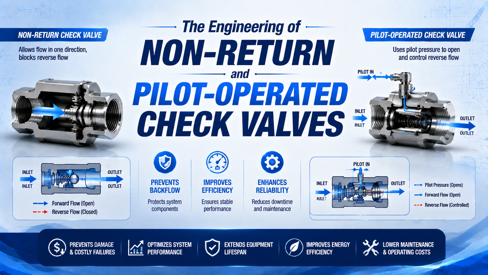
A non-return valve blocks reverse flow automatically, while a pilot-operated check valve adds a control port that can deliberately release the blocked path. Choose between them from the required circuit state, cracking pressure, forward-flow loss, reverse leakage, pilot-release condition, and safe behavior after pressure loss. Neither valve type guarantees zero leakage or safe mechanical restraint by category name alone.
Key Takeaways
- Festo lists a 0.1 bar minimum opening differential for specific H-series check valves under its published test conditions, not for every pneumatic check valve.
- Pilot pressure must overcome locked-port pressure, spring force, friction, and any back pressure.
- Pressure retention and safe load restraint are separate acceptance tests.
This article focuses on the engineering difference between two-port automatic checks and pilot-released checks. For a broader overview of check-valve types, installation, leakage testing, and RFQ data, use the pneumatic check valve function guide.
What Engineering Difference Separates the Two Valve Types?
Festo’s 2026 H datasheet identifies a two-port non-return function, while its HGL datasheet identifies a pneumatically piloted non-return function with a separate pilot connection. Adding that port changes the circuit from automatic reverse blocking to commanded release (Festo H, Festo HGL, 2026).
A non-return valve is a two-port element that permits forward flow after inlet pressure overcomes the closing forces and then blocks reverse flow. Possible closing elements include a poppet, ball, diaphragm, or elastomeric sleeve. Behavior depends on pressure differential, spring force, friction, orientation, and the seat design.
A pilot-operated check valve is a non-return element plus a pilot actuator. Without sufficient pilot force, it blocks the designated reverse path. With sufficient pilot force, an internal piston or plunger unseats the check element so the trapped side can discharge through the main port.
Draw each operating state before choosing the hardware. Mark the free-flow direction, the pressure-retaining direction, the pilot source, and the destination of released air. Then repeat the drawing for normal motion, stopped motion, supply loss, pilot loss, electrical loss, and maintenance exhaust. This exercise often reveals a missing exhaust path or a pilot signal that disappears in the same event that the valve is expected to release. Port labels on the actual datasheet must match the schematic.
| Engineering question | Non-return valve | Pilot-operated check valve |
|---|---|---|
| How does it open in the free direction? | Forward differential overcomes closing force | Same basic check action |
| Can the blocked direction be opened on command? | No | Yes, with adequate pilot force |
| Number of functional pressure inputs | Two main ports | Two main ports plus pilot input |
| Typical purpose | Branch isolation, reverse-flow prevention, bypass path | Controlled pressure retention and release |
| Main hidden risk | Pressure loss or leakage is assumed to be zero | Pilot release, residual energy, or leakage is assumed to be controlled |
Port count is only the beginning.
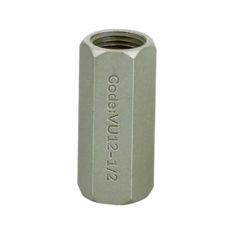
Function matters more than housing appearance. One-way speed controllers also contain a check element, but a parallel needle path meters flow in the other direction. Evaluate that arrangement with the meter-in versus meter-out control guide rather than treating it as a plain check valve.
How Does a Non-Return Valve Open and Close?
Festo publishes a 0.1 bar minimum opening differential for specific H-series push-in check valves and an operating range from -1 to 10 bar. Its threaded variants show different pressure ranges, proving that cracking pressure and rating belong to the selected model (Festo H datasheet, 2026).
Forward pressure opens the moving element only after its force exceeds everything holding the element on the seat. A simplified opening condition is:
Here, is inlet pressure, is downstream pressure, is the effective seat area, is spring force, and represents seal and guide friction. Use this relationship as a force model, not as a substitute for the manufacturer’s tested cracking-pressure value.
The corresponding differential is:
Cracking is not full opening.
At the stated cracking point, the poppet or sleeve may be barely lifted, so full catalog flow can require a larger differential. Low cracking pressure therefore doesn’t prove low pressure drop at production flow.
When the differential reverses, downstream pressure assists the spring in seating the element. Reverse sealing still isn’t mathematically perfect. Seat finish, elastomer condition, particles, temperature, pressure differential, orientation, and test duration all affect measured leakage.
Treat one body as two components during acceptance: a forward-flow restriction and a reverse-flow seal. Passing one test says nothing conclusive about the other. Record pressure loss at required flow separately from reverse leakage at a stated differential and stabilization time.
How Does Pilot Pressure Release a Locked Check?
Festo’s 2026 HGL family is rated for 0.5 to 10 bar operating pressure, while listed pilot ranges are 2 to 10 bar for some sizes and 1 to 10 bar for others. Instead of one universal ratio, the catalog provides minimum-pilot-pressure curves (Festo HGL datasheet, 2026).
Pilot pressure acts on a larger internal area to create opening force. Locked-port pressure acts on the check seat area in the closing direction. Valve-side pressure may assist opening, while spring force, seal friction, and back pressure resist it.
A simplified release condition is:
is pilot pressure, is pilot-piston area, is pressure at the valve-side main port, is trapped or load-side pressure, and is the effective check-seat area. Internal construction determines which terms and pressures reach each control area.
Pilot ratio is the manufacturer’s defined relationship between the pilot-control area and the check-seat control area. If it is defined as , a simplified pressure estimate becomes:
This equation explains the dependencies, but the selected manufacturer’s curve governs. Catalog definitions can include different control areas, seals, springs, and back-pressure assumptions. Don’t transfer a 3:1 or 5:1 ratio from a hydraulic cartridge to an unrelated pneumatic fitting.
Back pressure deserves its own measurement. A silencer, restricted directional-valve exhaust, shared manifold, or long pilot tube can change the force balance during the short release event even when steady-state supply pressure looks adequate. Pilot pressure should be measured at the valve’s pilot port, not only at the upstream regulator. When a pilot signal is borrowed from the opposite cylinder line, verify that the line develops enough pressure before motion or exhaust causes the locked-port pressure to change.
For instance, suppose a hypothetical valve defines , the locked port is at 6 bar, the valve-side port is at 1 bar, and the spring-plus-friction term equals 0.2 bar on the pilot side. Calculation gives . This example explains sensitivity only; use the selected pneumatic valve’s published curve for approval.
The catalog still decides.
The pressure-differential force guide covers the underlying pressure-area relationship. For general pilot-stage behavior outside a locked check function, see how pilot-operated valves work.
Release Sequence and Trapped-Air Behavior
SMC warns that a pilot check in a balance-control circuit may fail to release even when pilot pressure equals 50% of operating pressure. Its ASP documentation also requires consideration of residual-pressure release because an actuator can move suddenly during maintenance (SMC ASP, 2024).
Release can be more hazardous than the holding period. If a vertical or externally loaded actuator is trapped at pressure and the pilot check opens into a low-pressure exhaust path, stored pneumatic energy can accelerate the load before the directional circuit establishes controlled chamber pressure.
Use a defined sequence:
- Establish the directional-valve state that will control both actuator chambers.
- Confirm adequate supply and exhaust capacity for the intended direction.
- Apply pilot pressure and verify the check valve releases at the worst locked-port pressure.
- Meter actuator motion with the approved speed-control arrangement.
- Stop in a defined state and verify leakage or movement against the acceptance limit.
- Before maintenance, mechanically secure the load and dissipate residual pressure through the designed path.
Release must be controlled.
SMC offers ASP variants with a manual residual-pressure release function. That feature is product-specific. It does not authorize opening a pressurized line or working under an unsupported load. Maintenance procedures must identify the isolation boundary, mechanical restraint, exhaust path, and method used to verify zero hazardous energy.
Loss-of-supply behavior must also be specified. Some circuits are intended to trap pressure when the directional valve or main supply vents; others must move to a depressurized condition. A trapped-pressure design can retain energy after the upstream gauge reads zero, while an automatic release can allow an external load to move. Neither outcome is universally safer. Define the required machine state first, then select monitored valves, mechanical restraints, and exhaust devices that produce and verify that state.
In our experience reviewing hold circuits, the most revealing commissioning test measures pilot pressure, locked-port pressure, and actuator movement on the same time base. Static gauges can miss a short pilot-pressure collapse or delayed exhaust that prevents clean release.
Which Data Determines Flow and Pressure Loss?
Festo’s 2026 HGL datasheet lists standard nominal flows from 130 to 1,600 L/min across its threaded sizes and standard flows up to 2,100 L/min under another stated pressure condition. ISO 6358-1 defines steady-state pneumatic flow testing, with a 2026 amendment covering uncertainty evaluation (Festo HGL, ISO 6358-1 Amendment 2, 2026).
Compare valves only under matched test conditions. For example, Festo reports different HGL flow values under 6-to-5 bar and 6-to-0 bar conditions. Without the pressure condition, reference atmosphere, temperature, and flow direction, a nominal L/min value is incomplete. Cracking pressure is also not a flow coefficient; it marks initial opening, not loss at production flow.
Gather these data for the free-flow direction:
- minimum upstream pressure during peak demand;
- downstream pressure before opening and while flowing;
- required normal and peak standardized airflow, including any short exhaust demand that controls the real actuator release time;
- ISO 6358 sonic conductance and critical pressure ratio, or the manufacturer’s fully stated alternative test method and reference conditions;
- forward pressure drop at the required flow;
- tube, fitting, silencer, manifold, and directional-valve losses;
- temperature, medium quality, lubrication policy, and mounting orientation.
For preliminary comparison, the Cv Flow Coefficient Calculator can relate flow, coefficient, and differential pressure. Pneumatic selection still requires the manufacturer’s compressible-flow method. For the gas-flow assumptions behind that decision, use the valve pressure-drop guide.
Measure pressure close to both main ports during the actual motion. If pressure loss appears only at high speed, inspect the complete air path before replacing the check valve. Centralized valve placement, long tubing, restricted silencers, and undersized fittings can create the same symptom; see the pneumatic valve placement guide.
A practical flow test should capture more than one operating point. Record the minimum-supply, normal-demand condition that exposes hesitation, then repeat at the maximum expected simultaneous demand and at the commanded release of a trapped actuator chamber. Save upstream pressure, downstream pressure, standardized flow, actuator travel time, pilot pressure, and temperature on the same record. If the valve is removable, compare its measured loss with a temporary reference passage only under a controlled and safe test arrangement. This separates component restriction from tube, fitting, silencer, and directional-valve losses without relying on port size or a static gauge. Repeat any abnormal point to distinguish a persistent restriction from a transient supply event or a particle that moved between cycles.
Pilot release and main flow are separate capacity checks. Successful unlocking can still leave an exhaust restriction large enough to destabilize motion. Conversely, a high-flow main passage doesn’t prove the pilot circuit can release the worst trapped pressure.
Can a Pilot-Operated Check Valve Hold a Cylinder Safely?
SMC states that its ASP pilot check cannot provide accurate intermediate stops and isn’t guaranteed to hold a stop position for an extended period because valves and actuators aren’t guaranteed zero leakage. Festo states that safety-related use of HGL valves requires additional measures (SMC ASP, Festo HGL, 2024-2026).
Air is compressible. Temperature changes, tubing expansion, load movement, or opposite-chamber venting can all alter a trapped chamber’s pressure. Cylinder seals, tube connections, and the check seat also have finite leakage. Therefore, a stable gauge reading and safe mechanical restraint are different claims.
Use three distinct acceptance questions:
| Acceptance question | What to measure | What it does not prove |
|---|---|---|
| Does the valve retain pressure? | Reverse leakage or pressure decay across a defined boundary | That the actuator cannot move |
| Does the actuator remain within tolerance? | Position drift under stated load, time, temperature, and pressure | Personnel safety after a component failure |
| Is hazardous movement prevented? | Complete risk-reduction function under defined faults | That one pneumatic valve is sufficient |
Pressure retention is not restraint.
ISO 4414 addresses significant hazards in pneumatic systems and principles for avoiding them in intended use. OSHA 29 CFR 1910.147 addresses hazardous-energy control during covered servicing activities (ISO 4414, confirmed 2021; OSHA, retrieved 2026-07-19).
Where motion can injure someone, the design may require a rated rod lock, brake, prop, pin, blocking device, redundant monitored pneumatic function, or another engineered restraint selected through the machine risk assessment. Used as one layer, a check valve may contribute, but calling it “fail-safe” without a verified architecture and fault response is not acceptable.
Run holding and safety tests separately. The holding test can record chamber pressure and position drift for a defined load, time, temperature, and starting pressure. The safety validation must consider faults such as a leaking seat, failed tube, unintended pilot signal, lost supply, or failed cylinder seal. Passing the first test doesn’t automatically satisfy the second. Document which hardware prevents hazardous motion, how its state is monitored, and how maintenance personnel verify the restraint before entering the danger zone.
The cylinder rod-lock guide explains the difference between pneumatic pressure retention and mechanical clamping. Always secure a suspended or externally loaded axis before opening the pneumatic boundary.
Fault Diagnosis: Pressure, Leakage, and Chatter
Festo rates current HGL variants for operating and media temperatures from -10 to 60°C and specifies compressed-air quality for the series. Those product limits matter because seal friction, contamination, and material behavior can change opening, release, and leakage performance (Festo HGL datasheet, 2026).
Start diagnostics from a safe machine state, then record pressures at all functional ports. Don’t infer valve failure from a cylinder that drifts. Remember that the test boundary may also contain cylinder seals, fittings, tubing, a venting regulator, or a directional valve.
| Symptom | Check-valve causes | Other causes to exclude | Decisive measurement |
|---|---|---|---|
| Slow free-direction motion | High cracking pressure, small passage, contamination | Low supply, small tube, restricted exhaust | Dynamic pressure on both main ports |
| Reverse pressure decay | Seat damage, particle, incompatible seal | Cylinder or fitting leakage | Isolated reverse-leakage test |
| Pilot check won’t release | Low pilot pressure, high locked pressure, back pressure, wrong porting | Directional-valve state or blocked pilot tube | Pilot and locked-port pressure together |
| Sudden motion on release | Fast decompression into low pressure | Poor brake sequence or exhausted opposing chamber | Synchronized pressure and position trace |
| Chatter or repeated opening | Marginal differential, unstable element | Regulator instability, pulsation, vibration | Fast upstream/downstream pressure trace |
Contamination can create intermittent behavior. One particle may hold the seat open during a cycle and move during the next. Inspect removed parts for thread-seal debris, elastomer damage, lubricant deposits, corrosion, and seat marks. Correct the source rather than treating replacement as the entire repair.
Instrumentation determines what can be diagnosed. Use pressure sensors or gauges with enough range, accuracy, and response time for the event, and place them close enough to separate the valve from upstream tubing losses. A position trace or high-speed video can show whether motion starts before, during, or after pilot release. For leakage tests, define the isolated volume and allow temperature to stabilize. Otherwise, pressure decay from cooling or another component may be assigned incorrectly to the check valve.
Maintenance intervals should follow the exact product documentation, cycle count, leakage trend, contamination history, environment, and consequence of failure. Calendar-only monthly or annual replacement schedules aren’t defensible for every valve and duty.
Selection and Commissioning Checklist
ISO 4414 applies throughout the machine lifecycle to pneumatic-system design, construction, modification, installation, adjustment, operation, and maintenance. Its scope is broader than a valve pressure rating, so selection should document function and failure behavior alongside the component data (ISO 4414, confirmed 2021).
Before ordering, record:
- free-flow and blocked-flow directions on a marked circuit schematic;
- valve type: non-return, pilot-operated check, or one-way flow control;
- medium, filtration, lubrication, moisture, and chemical compatibility;
- minimum, normal, and maximum pressure at every functional port;
- required flow and maximum permissible forward pressure drop;
- cracking pressure and reverse-leakage acceptance condition;
- for a pilot check, minimum pilot pressure, maximum locked-port pressure, the exact manufacturer pilot curve or ratio definition, and permitted back pressure at every relevant port;
- state after loss of pilot pressure, supply pressure, and electrical power;
- residual-pressure release method and safe servicing boundary;
- port standard, tube size, mounting orientation, temperature, vibration, and corrosion exposure;
- load-holding duration and permissible drift;
- any personnel-safety requirement, including the mechanical restraint and verification method selected through the machine risk assessment.
During commissioning:
- Confirm port markings and free-flow direction before pressurizing.
- Flush or clean new lines so chips and sealant cannot reach the seat.
- Test free flow at maximum required demand and minimum available supply pressure.
- Measure reverse leakage at a defined differential, temperature, and duration.
- Test pilot release at maximum locked pressure and minimum pilot pressure.
- Observe release speed, actuator acceleration, and the opposing chamber pressure.
- Verify the defined state after pilot, supply, or electrical loss.
- Secure the load and verify residual-pressure dissipation before maintenance release.
Record the complete test configuration so the result can be repeated after maintenance. Include valve model and revision, port mapping, tube lengths and inside diameters, sensor locations, instrument accuracy and sample rate, supply setting, locked-port pressure, pilot pressure, load, actuator position, ambient temperature, and stabilization time. Photographs of the installed port markings and a marked schematic help prevent a later replacement from reversing the free-flow direction. When acceptance depends on a controller sequence, archive the relevant valve timing and output state with the pressure trace instead of recording only a verbal pass or fail. If a parameter changes later, the record shows which release, flow, leakage, and safety tests must be repeated before production resumes.
Acceptance criteria should be numeric and product-specific. Useful examples include maximum forward loss at stated flow, maximum reverse leakage at stated differential, successful release above a measured minimum pilot pressure, position drift over a defined time, and no hazardous movement during the specified fault sequence.
Check Valve FAQs: What Should Engineers Verify?
SMC documents four distinct limits for its ASP pilot check: no precise intermediate stop, no guaranteed extended holding, residual-pressure hazards, and possible failure to release at a 50% pilot-to-operating-pressure relationship. Each answer keeps those functions separate instead of treating “pilot operated” as a universal performance guarantee (SMC ASP, 2024).
Is cracking pressure the same as full-flow pressure drop?
No. Cracking pressure is the differential at which the closing element begins to move. Full flow normally requires more lift and a larger differential. Festo lists 0.1 bar for specific H-series opening conditions, but final selection must use the exact model’s flow data at the required pneumatic test condition.
Can a pilot-operated check valve open with any pilot signal?
No. Pilot force must overcome locked-port pressure, spring force, friction, and relevant back pressure. Festo publishes size-specific minimum-pilot-pressure curves and different pilot ranges within the HGL family. Measure the worst pressure combination and follow that product curve instead of assuming one universal pilot ratio.
Will a pilot check hold a cylinder at an exact intermediate position?
Not by itself. According to SMC, compressed air can continue moving an actuator until chamber pressures balance, even after its ASP pilot check closes. Valve, cylinder, and connection leakage can also create drift. Specify a measurable position-and-time tolerance and add mechanical holding when the risk or process requires it.
What happens if trapped pressure is released too quickly?
Rapid decompression can accelerate the actuator if a loaded chamber opens into a low-pressure exhaust path before opposing-chamber control is established. Sequence the directional valve, pilot signal, metering path, and brake or restraint together. SMC’s documentation specifically requires residual-pressure consideration, including a safe manual release arrangement where the selected variant provides one.
Can a check valve be the only protection for a suspended load?
It shouldn’t be assumed sufficient. ISO 4414 requires pneumatic hazards to be addressed at system level, while Festo states that HGL use in safety-related applications needs additional measures. Evaluate leakage, hose or fitting failure, unintended pilot release, stored energy, and mechanical restraint through the machine risk assessment.
Sources and technical references
- Festo H, HA, HB check valves: model-specific function, opening differential, pressure, temperature, and material data. Retrieved 2026-07-19.
- Festo HGL piloted check valves: operating pressure, pilot pressure, flow, temperature, and minimum pilot-pressure curves. Retrieved 2026-07-19.
- Festo HGL characteristics: pilot function, manual exhaust option, and safety-related-use warning. Retrieved 2026-07-19.
- SMC ASP speed controller with pilot check: manufacturer warnings covering intermediate-stop accuracy, non-zero leakage, extended holding, residual-pressure release, balance circuits, and minimum pilot-pressure behavior. Retrieved 2026-07-19.
- ISO 6358-1:2013/Amd 2:2026: 2026 amendment on evaluating uncertainty in pneumatic steady-state flow measurements. Retrieved 2026-07-19.
- ISO 4414:2010: pneumatic system safety rules. Retrieved 2026-07-19.
- OSHA Control of Hazardous Energy: hazardous-energy control requirements and guidance for covered servicing activities. Retrieved 2026-07-19.