

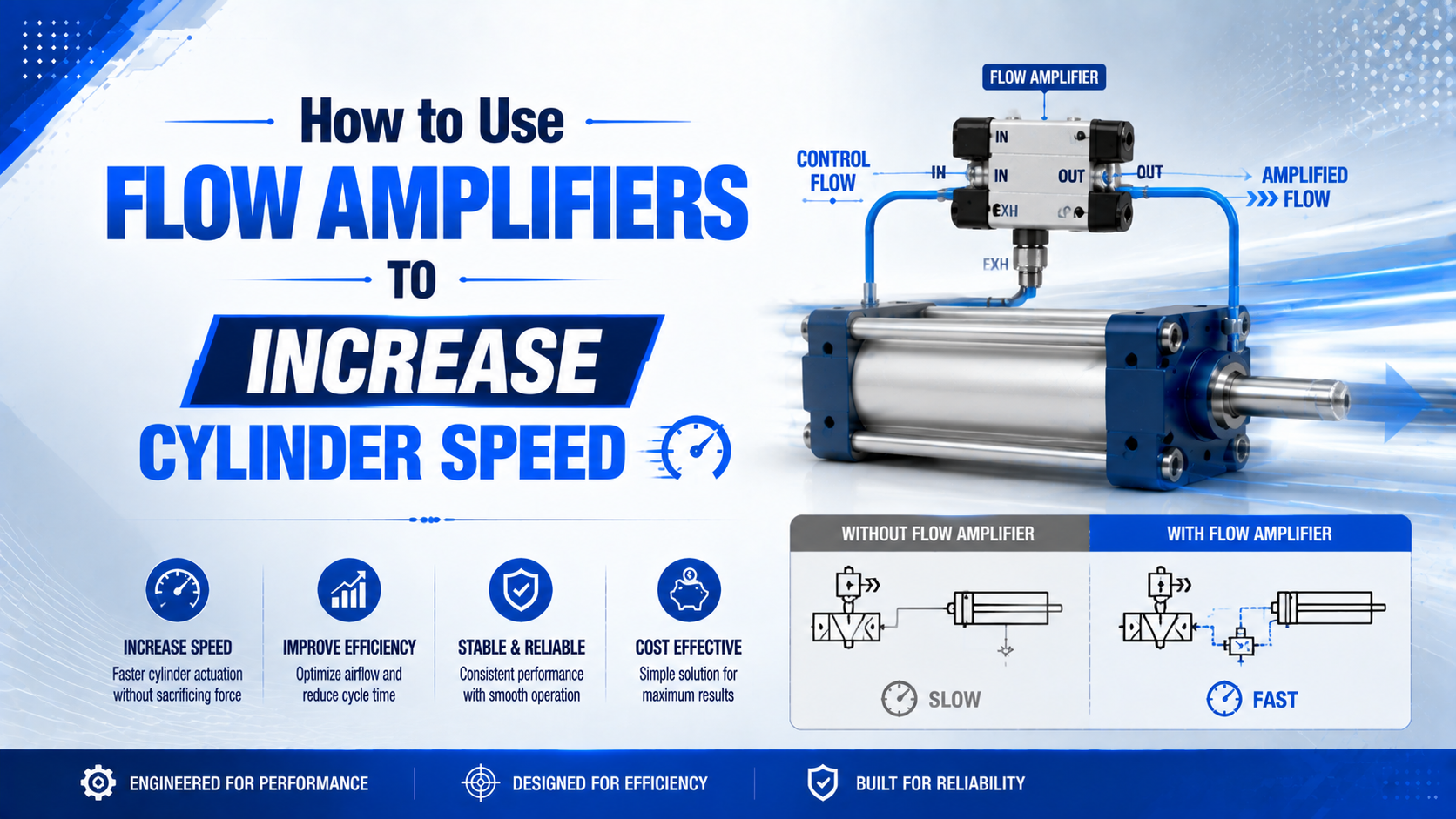
Do not pipe an ambient-air flow amplifier into a standard pneumatic cylinder and expect it to multiply working flow at full pressure. An air amplifier entrains surrounding air into an open discharge. A sealed cylinder chamber needs compressed airflow at enough dynamic pressure to move its load. For ordinary cylinders, increase usable supply flow or reduce exhaust restriction. For positioner-controlled valve actuators, a volume booster may be appropriate.
EXAIR publishes ambient-air amplification ratios up to 25:1 for cooling, drying, ventilation, and fume movement, yet the manufacturer also states that these units do not increase compressed-air system pressure. That distinction changes the whole retrofit. A large open-air flow number is not the same as pressurized flow delivered through a valve and tube to a cylinder port (EXAIR Super Air Amplifier; EXAIR pressure versus flow, accessed July 19, 2026).
Key Takeaways
- A 25:1 ambient-air ratio is an open-discharge figure, not a cylinder speed multiplier.
- Ordinary cylinders usually need more supply capacity, less exhaust restriction, or a quick exhaust valve.
- Volume boosters belong to compatible positioner-actuator control loops.
- Measure dynamic port pressure and stop energy before approving a faster stroke.
From our analysis of manufacturer data, the word amplifier hides three different engineering outputs: ambient-air volume, control-signal flow, and pressure. Only one may match the motion problem. Classify the device by what enters, what leaves, and whether the outlet must remain above atmospheric pressure before comparing any ratio.
What Is a Flow Amplifier, and Why Can’t It Pressurize a Cylinder?
EXAIR rates some air amplifiers at up to 25 parts of total outlet flow for each part of compressed-air consumption. The outlet combines the primary jet with entrained room air and discharges at high volume for open-air work. It does not provide a 25-times pressurized supply to a sealed actuator chamber (EXAIR, accessed July 19, 2026).
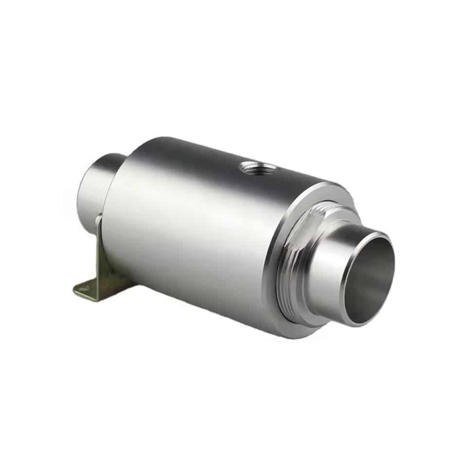
Ambient-air flow amplifier is an air mover that uses a compressed primary jet to entrain surrounding air. EXAIR describes an annular chamber, a small ring nozzle, the Coanda profile, and a low-pressure central region. The combined stream leaves the device as an open high-volume, high-velocity flow.
A standard cylinder works differently. Its directional valve must fill one closed chamber to a pressure high enough to overcome opposing chamber pressure, seal friction, external load, and acceleration force. Atmospheric air drawn into an open air mover can’t enter that chamber and remain at the required gauge pressure without another compression stage.
What happens if the air-amplifier outlet is sealed to a cylinder port? Entrainment falls as outlet back pressure rises, so the advertised open-flow ratio no longer describes the operating point. The device may consume compressed air without providing the force or repeatable stroke time the machine needs.
Use ambient-air amplifiers for their documented applications: part cooling, drying, ventilation, smoke or fume movement, heat distribution, and light-material transport. Do not use those open-flow ratios to size a cylinder circuit.
Four Devices Commonly Confused as Flow Amplifiers
Two published ratios show why names are unsafe selection data. An EXAIR air mover can advertise 25:1 ambient-air amplification, while Emerson describes its 2625 volume booster as a 1:1 pressure device with designed deadband. Both are called boosters or amplifiers in conversation, but they solve different problems (EXAIR; Emerson 2625 manual).
| Device | What it changes | Appropriate use | Wrong assumption |
|---|---|---|---|
| Ambient-air flow amplifier | Open-discharge volume by entraining room air | Cooling, drying, ventilation, fume movement | The outlet can fill a loaded cylinder at plant pressure |
| Pneumatic volume booster | Supply and exhaust flow following a control signal | Compatible positioner-controlled valve actuators | It is a universal add-on for every machine cylinder |
| Pressure booster regulator | Outlet pressure using drive air and cyclic compression | Small local high-pressure zone with bounded demand | Higher static pressure fixes an undersized flow path |
| Quick exhaust or speed exhaust valve | Exhaust capacity close to the cylinder port | Reducing return-path restriction on an ordinary cylinder | It increases supply flow in both directions automatically |
Do you need pressure rather than speed? Read How Can Pneumatic Pressure Boosters Transform Your Industrial Operations and Slash Equipment Costs?. A pressure booster is defensible only after dynamic measurements show that the load lacks pressure and the circuit can supply its inlet demand.
How Does Airflow Set Cylinder Speed?
SMC gives the customary-unit relationship when inlet pressure is held constant, with speed in inches per second, airflow in SCFM, and piston area in square inches. The relation captures the direction of change, but actual speed also depends on ports, tubing, load, and exhaust restriction (SMC cylinder airflow guidance, accessed July 19, 2026).
At chamber conditions, the basic relationship is:
Here, is piston speed, is volumetric flow at the chamber’s actual pressure and temperature, and is piston area for extension or annular area for retraction. Do not divide a catalog standard-flow value directly by piston area without converting it to the chamber condition.
For a first timing estimate at chamber conditions:
In this equation, is stroke and is the target travel time. Dead volume, compressibility, acceleration, valve response, leakage, cushion restriction, and changing chamber pressure make the real stroke slower than this ideal volume-over-time estimate.
If target time is known instead of available flow, use the Cylinder Flow Requirement Calculator as a secondary estimate. Then compare that demand with manufacturer flow curves for the complete supply and exhaust paths.
Which Restriction Is Actually Limiting the Stroke?
CAGI recommends limiting total pressure drop from compressor discharge to point of use to about 10% in a well-designed plant-air system. A machine can still lose additional pressure through its regulator, valve, tube, fittings, controller, port, and muffler. Measure during motion because a static gauge hides active flow loss (CAGI Pressure Drop Technical Brief, accessed July 19, 2026).
Use three synchronized measurements: valve-inlet pressure, both cylinder-port pressures, and stroke time. Add exhaust pressure when a silencer, manifold, or long return path is suspect. Test extension and retraction separately because a 5/2 valve uses different internal passages in each direction.
| Symptom | First measurement | Likely next check |
|---|---|---|
| Both directions slow | Valve-inlet pressure during travel | FRL, branch tubing, shared demand, or regulator capacity |
| One direction slow | Both port pressures in that direction | Valve path, controller, fitting, tube, or cylinder port |
| Inlet pressure stable, opposite chamber stays high | Exhaust-side pressure | Meter-out setting, muffler, manifold, or return tube |
| Speed improves unloaded but not under load | Driving pressure difference | Bore, friction, side load, force margin, or pressure loss |
| Speed falls near stroke end | Both chambers and position | Cushion needle, load change, or stop arrangement |
If a restriction reaches choked flow, a larger downstream air mover won’t change the controlling throat. The choked-flow and cylinder-speed guide explains the 0.528 ideal-air pressure-ratio boundary and the required absolute-pressure calculation.
For ordinary flow loss, follow the compressed-air pressure-drop troubleshooting guide. Change one component at a time, then repeat the same pressure trace and timed stroke.
From our analysis of the documented supply and exhaust paths, the faster-side modification is often on the chamber that must exhaust, not the chamber being filled. A high static supply gauge can distract from trapped back pressure on the opposite side. Ask which measured pressure difference changes while the piston moves, not how much flow a new device advertises.
When Does a Volume Booster Belong in the Circuit?
Emerson documents the Fisher 2625 as a 1:1 device with designed deadband, and its VBL booster is specifically used with a positioner on a throttling control valve to increase actuator stroking speed. The booster supplies high flow for large signal changes while a bypass supports stable response to small changes (Emerson 2625 manual; Fisher VBL).
Pneumatic volume booster is a high-capacity relay that follows a compatible control signal while drawing working air from its own supply connection. It does not entrain atmosphere. It fills or exhausts the actuator faster than the positioner’s small internal relay could by itself.
Use one only when the actuator, positioner, booster, fail action, and tuning method form a documented system. Verify:
- Input and output pressure range
- Supply and exhaust flow coefficients
- Deadband and bypass adjustment
- Positioner compatibility and common supply requirements
- Small-signal stability and large-signal stroke time
- Fail-safe response, partial-stroke testing, and required proof tests
- Air quality, temperature, mounting, and exhaust routing
A poorly tuned bypass can slow a fail-safe stroke or destabilize control. That is why a control-valve volume booster isn’t a drop-in substitute for the directional valve on a packaging cylinder. For a simple on/off cylinder, start with the actual valve, tubing, and exhaust path.
Quick Exhaust for Ordinary Cylinder Speed
SMC’s compact JASV speed exhaust controller is 12.7 mm shorter than the preceding arrangement, a 49% reduction, and its direct exhaust port relieves cylinder pressure regardless of tubing length. Festo likewise says its SE/SEU quick exhaust valve should mount directly at the cylinder connection for full, fast exhausting (SMC JASV; Festo SE/SEU).
A quick exhaust valve routes cylinder air to atmosphere near the actuator instead of sending it back through the long tube and directional valve exhaust. This can reduce back pressure and speed the motion driven by the opposite chamber.
It doesn’t automatically accelerate both directions. One valve affects the cylinder port where it is installed. A double-acting cylinder may need a different arrangement for the opposite direction, but adding two devices without a load and stop review can produce uncontrolled motion.
Keep these constraints in the design:
- Mount close to the cylinder port as the manufacturer specifies.
- Match port size and tested flow data to the actual cylinder demand.
- Keep an approved speed-control method when the load requires metered motion.
- Route exhaust away from people, contamination-sensitive work, and unsafe noise exposure.
- Check whether the silencer reduces the required exhaust capacity.
- Confirm vertical-load behavior, especially with overrunning loads.
- Recalculate cushion and shock-absorber energy after speed changes.
This section only establishes when quick exhaust is the correct device class. For port operation, placement, Cv, silencers, and detailed RFQ inputs, use How Does a Quick Exhaust Valve Work and Why Should You Care?. The meter-out circuit guide explains when exhaust restriction is deliberately retained for stable motion.
How Should You Size and Install the Retrofit?
SMC’s AQ quick-exhaust family spans ports from M5 to 3/4 inch, which shows why “install a quick exhaust” isn’t a complete specification. The chosen part must pass the required flow at the operating pressures and fit the motion direction, tube, cylinder port, exhaust treatment, and environment (SMC AQ, accessed July 19, 2026).
Use this sequence:
- Record bore, rod diameter, stroke, moving mass, orientation, load, current time, and target time.
- Calculate extension and retraction flow demand on the same reference basis as the component data.
- Measure dynamic valve-inlet and cylinder-port pressures during both directions.
- Identify whether supply, working-port, or exhaust loss is controlling the stroke.
- Compare valve and quick-exhaust curves at the real pressure ratio, not only the largest catalog flow.
- Check tube inside diameter, length, fittings, controllers, and cylinder-port adapters.
- Install the selected device in the manufacturer’s orientation and location.
- Start at low speed, then increase flow while recording pressure, time, rebound, and noise.
- Repeat at minimum and maximum load and at the sustained production cycle rate.
If the directional valve is the limit, size its active supply and exhaust passages before adding another component. The pneumatic valve Cv guide explains why a single nominal port size cannot establish capacity.
Do not raise regulator pressure simply to shorten the stroke. Higher pressure changes thrust, air consumption, stored energy, and possible fault force. A corrected tube or exhaust path may recover speed without increasing the cylinder’s maximum force.
Speed Gains Create a Stopping-Energy Problem
Parker warns that cushion-entry speed can be about 50% higher than average stroke speed in its cylinder guidance. That difference matters because kinetic energy follows speed squared. A cylinder that survives its average-speed estimate may exceed the built-in cushion limit as it enters the end zone (Parker P1F, accessed July 19, 2026).
The first kinetic-energy check is:
Here, is kinetic energy in joules, is total moving mass in kilograms, and is speed in metres per second at the start of deceleration. Doubling speed creates four times the kinetic energy at the same mass. Tripling speed creates nine times the energy.
That equation is only a starting point. Gravity, external drive force, cylinder thrust during cushioning, off-center moment, stop stroke, shock-absorber cycle rate, and temperature can change the selection. Use the exact manufacturer’s cushion or shock-absorber method.
Review guards, hose restraint, sensor timing, valve response, exhaust noise, rebound, and machine safe state. A faster cylinder may reach a person, fixture, or part before the control system expects it. The completed retrofit must pass both production timing and machinery risk review.
What Should Commissioning Measure?
Parker’s valve-sizing example uses a 3.25-inch bore, 12-inch stroke, 80 psig supply, and one-second stroke target to calculate Cv 1.06. The numbers are example-specific, but the method is general: define motion demand first, then prove the selected path at the real pressure and load (Parker pneumatic engineering data, accessed July 19, 2026).
Save a before-and-after trace with the same load, regulator setting, valve command, controller position, and production rate. Record:
- Valve-inlet pressure during the moving part of the stroke
- Both cylinder-port pressures versus time or position
- Command-to-motion delay and full stroke time in each direction
- Maximum repeatable cycle rate and supply recovery between cycles
- Cushion-entry behavior, final impact, rebound, and sensor confirmation
- Exhaust pressure, sound, temperature, leakage, and visible contamination
- Results at minimum and maximum payload
Acceptance should name the process result, not only a percentage improvement. For example: “The loaded cylinder shall extend from command to confirmed end position within the stated time while port pressure, impact, rebound, sound, and component ratings remain inside their defined limits.”
Our team analyzed the manufacturer selection methods around a pressure-time signature, not a speed percentage. If a quick exhaust valve lowers opposing chamber pressure and shortens the stroke, it addressed a real restriction. If stroke time changes while port pressures do not, review load, friction, sensing, and measurement timing before crediting the device.
For full high-speed actuator specification, use The Engineer’s Checklist for Specifying High-Speed Pneumatic Cylinders. This article’s narrower job is to choose the correct flow-changing device.
Flow Amplifier and Cylinder Speed FAQs
EXAIR publishes open-air amplification up to 25:1, while Emerson’s 2625 volume booster maintains a nominal 1:1 pressure relationship and Festo directs quick exhaust to the cylinder port. These numbers belong to different architectures. The answers below keep air movement, control-signal flow, pressure increase, and cylinder exhaust separate (EXAIR; Emerson; Festo).
Can an air amplifier be connected directly to a cylinder port?
An ambient-air amplifier shouldn’t be selected for that duty from its open-flow ratio. It entrains room air into an open discharge and does not raise compressed-air system pressure. A loaded cylinder needs pressurized chamber flow. Diagnose the valve, tubing, fittings, speed controller, cylinder port, and exhaust path instead.
Is a volume booster the same as a pressure booster?
No. A volume booster relays a compatible control signal with higher supply and exhaust capacity, commonly in a positioner-controlled valve actuator loop. A pressure booster uses drive energy to create a higher-pressure downstream zone. Their ratios, flow curves, controls, duty limits, and safety boundaries are different.
Will a quick exhaust valve increase both extension and retraction speed?
Not automatically. It increases exhaust capacity at the cylinder port where it is installed, so it normally affects the motion driven by the opposite chamber. Test both directions separately. A second quick exhaust may be possible, but load control, cushioning, noise, contamination, and safe failure behavior must still pass review.
Does a larger directional valve always make the cylinder faster?
No. A larger valve helps only when its active path is the controlling restriction and the rest of the circuit can supply and exhaust the added flow. A small regulator, tube, fitting, controller, port, or muffler may remain the limit. Confirm with dynamic pressure readings before changing hardware.
How do I verify that a speed increase is safe?
Measure both cylinder-port pressures and stroke time before and after the change at the real load and cycle rate. Then check cushion-entry speed, moving energy, rebound, shock capacity, sensor timing, exhaust noise, pressure ratings, and machine risk controls. Faster motion is acceptable only when timing and stopping limits both pass.
Sources and technical references
- EXAIR Super Air Amplifier, ambient-air entrainment, amplification ratio, and documented open-air applications. Accessed July 19, 2026.
- EXAIR Air Amplifiers: Pressure vs Flow, manufacturer’s distinction between increased open-discharge volume and compressed-air pressure. Published April 18, 2023.
- Emerson Fisher VBL Volume Booster, positioner-controlled actuator stroking and bypass function. Accessed July 19, 2026.
- Emerson Fisher 2625 Volume Booster Manual, 1:1 behavior, flow coefficients, supply connection, installation, and tuning. September 2022.
- SMC JASV Speed Exhaust Controller, direct cylinder exhaust and compact dimensions. Accessed July 19, 2026.
- Festo SE/SEU Quick Exhaust Valves, direct cylinder-port installation and increased piston-speed function. Catalog dated November 2025.
- SMC Cylinder Airflow Guidance, speed-flow-area relationship and exhaust-side speed control. Accessed July 19, 2026.
- CAGI Pressure Drop Technical Brief, system pressure-drop measurement and distribution guidance. Accessed July 19, 2026.
- Parker P1F Cylinder Catalog, cushion-entry speed and stopping guidance. Accessed July 19, 2026.
The Final Selection Rule
EXAIR’s 25:1 figure describes entrained open-air volume, Emerson’s 1:1 volume booster relays a control signal with higher capacity, and SMC and Festo quick exhaust devices remove cylinder back pressure locally. Choose the function that matches the measured restriction, then verify dynamic pressure, stroke time, and stopping energy under production load.
For most machine cylinders, the fix order is straightforward: calculate demand, measure both chambers, correct the largest supply or exhaust loss, and retest. Use an ambient-air amplifier only for open-air work. Use a volume booster only within its documented actuator-control architecture. Never treat an amplification ratio as a guaranteed cylinder speed gain.