

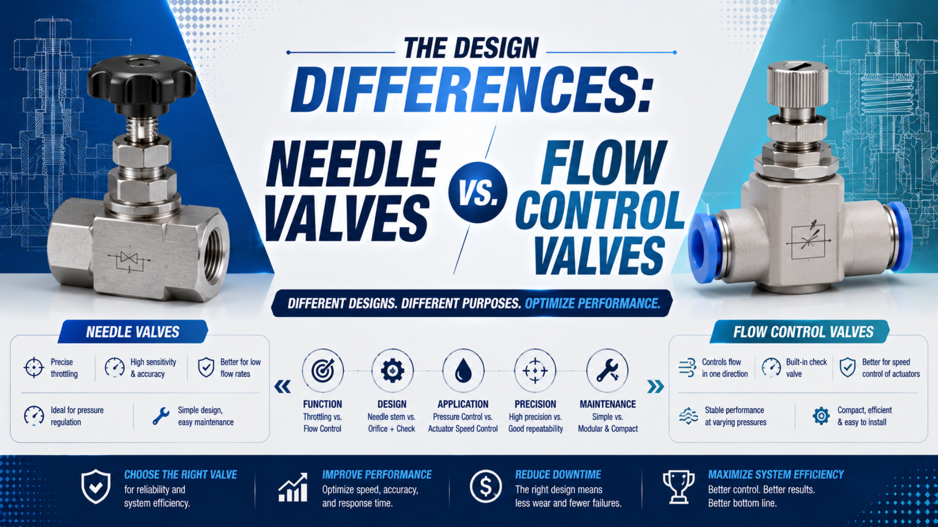
Needle valves are throttling mechanisms, while flow control valves form a broader functional category. A basic needle valve sends flow through one adjustable restriction. A common pneumatic speed controller combines that needle restriction with a check-valve bypass, so one direction is metered and the reverse direction follows a lower-restriction path.
This terminology is easy to misread because catalogs use “flow control,” “throttle,” “speed controller,” and “needle valve” differently. The parts are not always competing alternatives. In fact, the adjustment element inside a one-way pneumatic flow control is often a needle. The correct question is therefore not only “Which name is on the box?” It is “What flow path does the valve create in each direction?”
Key Takeaways
- One Festo model lists 95 L/min in the control direction and 76-95 L/min in the non-return direction.
- A needle describes the adjustable restriction; flow control describes the job.
- A pneumatic speed controller normally adds a check bypass.
- Confirm the symbol, arrow, and direction-specific data before installation.
For the wider family that includes manual, pressure-compensated, proportional, and servo-pneumatic options, see the guide to pneumatic flow control valve types. This article stays with the narrower mechanical comparison.
Are Needle Valves and Flow Control Valves Really Different Categories?
Not in a strict taxonomy. Swagelok places needle valves inside the flow-control family and describes their finely threaded stem and shaped tip as the features that provide gradual adjustment (Swagelok, accessed 2026). By contrast, pneumatic catalogs often use “flow control valve” as shorthand for a one-way cylinder speed controller.
Three terms should be separated:
| Term | What it describes | What it does not guarantee |
|---|---|---|
| needle valve | a tapered or shaped stem moving toward a seat or orifice | one-way bypass, pressure compensation, or cylinder suitability |
| throttle or two-way flow control | an adjustable restriction in the main path | free reverse flow or stable flow as pressure changes |
| one-way flow control or speed controller | an adjustable restriction plus a non-return bypass | zero pressure loss, a particular meter-in direction, or a specific flow capacity |
Festo’s product taxonomy makes the same distinction. It describes throttle valves as members of the flow-control group and one-way flow controls as devices that restrict one direction while providing the reverse direction through a non-return function (Festo, accessed 2026).
This is why a purchase request for “a flow control valve” is incomplete. The supplier still needs to know whether both directions should be throttled, whether one direction should bypass the adjustment, whether flow must remain stable as pressure changes, and whether an electrical command will change the setting.
Treat “needle” as a mechanism word and “flow control” as a function word. Once those layers are separated, most catalog-name arguments disappear.
How Does a Basic Needle Valve Control Flow?
Parker’s 338-series pneumatic needle valves are offered from 1/8 to 3/4 inch ports and are rated by that manufacturer for bidirectional air metering up to 250 psig (Parker 338 Series, accessed 2026). Those values describe one product family, not every needle valve.
A needle valve is an adjustable restriction formed by moving a tapered or shaped stem toward a seat or orifice. Turning the stem changes the available passage area and therefore the resistance to flow. A fine thread and long taper can spread the useful adjustment over more handle movement, but “more turns” is not automatically better. Usable resolution depends on stem contour, seat geometry, system pressure, gas properties, and where the normal operating point falls on the manufacturer’s flow curve. A basic two-way needle valve has one controlled passage, so flow from port A to port B and from B to port A both encounter that passage. However, capacity may not be identical in both directions because the internal geometry can be asymmetric. Use “bidirectional” only when the datasheet permits both directions and provides suitable performance information.
Needle valves also differ in shut-off capability. Swagelok notes that some needle designs can provide shut-off, while fine metering versions may not be designed as isolation valves. Don’t use a flow-setting stem as a lockout or safety-isolation device unless its manufacturer and the system design explicitly support that function.
Use a stand-alone needle or two-way throttle when the task genuinely calls for one adjustable restriction in both directions. Examples can include a controlled bleed, purge, small air jet, instrumentation line, or a stable manual flow setting. Media compatibility, shut-off requirement, adjustment locking, and the actual flow curve matter more than the generic name.
How Does a One-Way Pneumatic Flow Control Work?
A one-way pneumatic flow control is a combination of two parallel functions: an adjustable throttle and a non-return bypass. Festo describes that combination directly, while Parker describes metered flow in one direction and full flow in the other (Festo; Parker). In the metered direction, the check element closes and forces air through the adjustable needle passage. In reverse, pressure opens the non-return path and diverts much of the flow around the needle. The bypass lets a speed controller tune one chamber’s supply or exhaust without imposing the same setting on reverse flow. However, “full flow” is manufacturer shorthand, not a promise of zero resistance. The check element, fittings, body passages, and ports still consume pressure. Festo’s current GRLA-M5-RS-B page lists a standard nominal flow of 95 L/min in the control direction and 76-95 L/min in the non-return direction for that model (Festo GRLA, accessed 2026). Direction-specific numbers and test conditions are therefore essential.
The non-return path changes the circuit behavior, but it does not erase the valve’s flow limit. A speed controller can be correctly oriented and still be too small for the target stroke time.
What Can the External Appearance Tell You?
SMC offers AS speed controllers in inline and elbow constructions, with meter-in and meter-out versions identified by the flow-direction symbol on the body (SMC AS Series, accessed 2026). Body shape alone is therefore not enough to identify which direction is controlled.
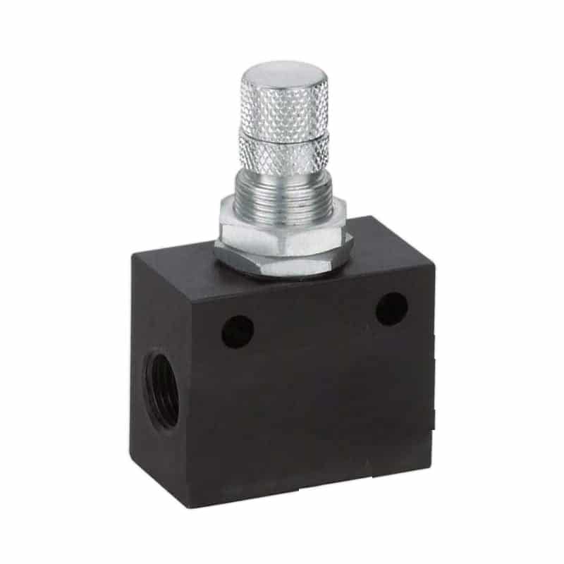
An external adjustment screw or knurled knob tells you that the valve is adjustable. It doesn’t prove whether the internal path is two-way or includes a check bypass. A locknut or detent tells you the setting can be retained, but it doesn’t establish flow capacity. Likewise, an elbow body suggests direct actuator mounting, yet both meter-in and meter-out variants may share nearly identical housings.
Use this identification order:
- Read the complete model number, including suffixes.
- Find the manufacturer symbol for that exact variant.
- Identify the flow-control direction and the non-return direction.
- Check any arrow on the body against the datasheet definition.
- Confirm whether the version is intended for supply-air or exhaust-air control.
- Verify port thread, tube size, pressure range, medium, temperature, and flow data.
ISO 1219-1 establishes rules for fluid-power graphical symbols, while ISO 1219-2 establishes rules for circuit diagrams that use those symbols (ISO 1219-1, 2012; ISO 1219-2, confirmed 2023). A symbol is functional: it tells you more about the intended paths than a product photograph can.
Which Valve Should Control Pneumatic Cylinder Speed?
Parker recommends two one-way flow controls for most double-acting cylinder applications so extension and retraction can be adjusted independently, and its instructions state that meter-out generally gives the best results (Parker). That is a practical starting point, not a universal rule for every load.
Meter-out control means metering air leaving the cylinder chamber while supply air reaches the filling chamber through the non-return path. The exhaust restriction creates back pressure that can resist a load trying to run ahead, which often helps vertical axes, changing loads, and long-stroke slides move more steadily. Meter-in control reverses that relationship: the valve meters air entering the active chamber and lets exhaust leave through the bypass. It can work for a stable resisting load, selected single-acting circuits, or a process that specifically requires free exhaust. However, it is less forgiving when gravity or an external force assists the stroke. SMC also describes exhaust-side control as the common industry practice and notes that cylinder speed depends on air flow, while port and tubing size remain additional constraints (SMC, Control Air Flow of Cylinders, accessed 2026). The choice is therefore a circuit decision, not merely a valve-body decision.
Use the dedicated comparison of meter-in and meter-out control when load direction and back pressure are the main questions. Use the flow control valve sizing guide when bore, stroke time, tubing, exhaust components, and catalog capacity must be calculated together.
Could a stand-alone needle valve move a cylinder more slowly? Yes. However, because it meters both directions through the same passage, it doesn’t provide the independent free-flow behavior that a one-way controller does. That may be acceptable in a deliberate low-flow circuit, but it should not be mistaken for equivalent cylinder-speed control.
When Is a Stand-Alone Needle Valve the Better Choice?
Parker’s 338-series example spans five nominal port sizes from 1/8 through 3/4 inch and uses a micrometer-marked adjustment for bidirectional pneumatic metering (Parker 338 Series). That construction suits a stable manual restriction better than a requirement for one-direction bypass.
Choose a stand-alone needle valve when all of these statements are true:
- both permitted flow directions may pass through the adjusted restriction
- the process needs a stable manual setting rather than a PLC command
- the manufacturer’s flow curve covers the required operating range
- the valve materials and seat design suit the gas or liquid
- any shut-off requirement is explicitly supported by the product
- the setting can be locked or protected as the machine requires
Common uses include controlled bleeds, analyzer or instrumentation lines, small purge flows, sampling arrangements, and manually adjusted air jets. The application may involve gas or liquid; “needle valve equals liquid” is not a valid classification rule.
A pressure-compensated valve is a different choice. It is intended to reduce the effect of changing pressure differential on the set flow. A proportional valve is different again because an electrical command changes the flow opening. Those functions are covered separately in the guides to pressure-compensated flow controls and proportional flow control valves.
In our experience reviewing applications, the most common mistake isn’t choosing a low-quality valve. It is specifying a good valve for the wrong flow function. From our work reviewing replacement requests, we found that writing “adjustable restriction in both directions” or “metered exhaust with free supply bypass” makes the requirement far harder to misinterpret.
Which Specifications Matter More Than Adjustment Turns?
ISO 6358-1 defines steady-state test methods for pneumatic components with fixed or variable internal flow paths, while ISO 6358-3 addresses the combined characteristics of components and piping (ISO 6358-1, 2013; ISO 6358-3, 2014). Those test conditions and flow data are more useful than a generic claim about knob turns.
Compare these fields for each candidate:
| Datasheet field | Why it matters | Comparison question |
|---|---|---|
| valve function and symbol | proves two-way throttle or one-way control | Is there a non-return bypass? |
| controlled direction | determines meter-in or meter-out behavior | What does the body arrow mean? |
| flow data by direction | reveals capacity of both internal paths | Are both directions rated under stated conditions? |
| useful adjustment curve | shows whether the target lies in a controllable range | Is most useful change crowded near closed? |
| pressure and temperature range | limits safe operation | Do minimum, normal, and maximum states fit? |
| operating medium and air quality | protects seals, seat, and check element | What filtration and lubrication does this model require? |
| port and tube size | affects connection and local restriction | Does the internal passage match the thread size? |
| adjustment lock | protects the commissioned setting | Locknut, detent, tamper-proof head, or none? |
| shut-off and leakage statement | separates metering from isolation | Is bubble-tight shut-off actually specified? |
| mounting and tightening data | prevents damaged threads and leaks | What torque and orientation does the manufacturer permit? |
Adjustment-turn counts are meaningful only within one design family. A four-turn stem with a well-shaped characteristic may offer more useful control around the operating point than a fifteen-turn valve whose capacity is concentrated near one end. Compare the setting-versus-flow curve whenever repeatable commissioning matters.
Cv can help compare capacity when the manufacturer supplies a matching pneumatic method. ISO 6358 sonic conductance and critical pressure ratio may be more direct for compressed-air components. Don’t mix a water-based Cv equation, an unrelated nominal L/min value, and an ISO conductance value in one calculation. Stay with one documented method from demand through selection.
How Should You Install and Commission the Selected Valve?
Parker instructs meter-out installations to point the full-flow arrow toward the cylinder port and meter-in installations to point it away, then to secure the locknut after adjustment (Parker). That rule belongs to the cited product design; another manufacturer’s arrow may be defined differently.
Use this commissioning sequence:
- Isolate and depressurize the relevant pneumatic energy according to the machine procedure.
- Confirm the exact model, symbol, port thread, and permitted flow direction.
- Install the device as close to the actuator port as practical when it is a cylinder speed controller.
- Use the specified seal or sealant method and tightening torque.
- Restore pressure under the approved restart procedure and check for leakage.
- Start from the manufacturer’s recommended adjustment position.
- Time repeated extension and retraction strokes under the real load.
- Measure pressure near the valve and cylinder if speed stops responding to adjustment.
- Secure the adjustment and record the final setting and stroke times.
In our experience commissioning pneumatic circuits, three symptoms quickly separate common faults. If turning the needle changes both directions, verify whether the device is a two-way throttle. If the adjustment changes the wrong stroke, verify the arrow and meter-in/meter-out variant. If the needle reaches fully open but the cylinder remains slow, look downstream and upstream for another restriction.
That other restriction may be the directional valve, tube ID, fitting, muffler, cushion needle, filter, regulator, or cylinder port. A one-way flow controller cannot add capacity that the rest of the path lacks. The guide to pneumatic check valves is useful when the bypass element itself leaks, sticks, or has the wrong cracking behavior.
Commission the two directions as two separate flow paths. Recording only one stroke can hide a reversed controller, a restricted check bypass, or an exhaust-side bottleneck.
Final Selection Rule
The decisive difference is the second path. A stand-alone needle valve meters through one adjustable passage. A one-way pneumatic speed controller adds a check bypass so the controlled and reverse directions behave differently. Pressure-compensated and proportional valves add still other functions.
Write the required behavior before selecting the part: two-way restriction, meter-in speed control, meter-out speed control, pressure-compensated flow, or electrically commanded flow. Then confirm the exact symbol, direction-specific performance, operating limits, and adjustment lock in the manufacturer’s documentation.
Names vary. Flow paths don’t.
FAQs About Needle Valves and Flow Control Valves
Is a needle valve a type of flow control valve?
Yes. A needle valve is one mechanical type of flow-control valve. In pneumatic catalogs, however, “flow control valve” often refers more narrowly to a one-way speed controller that combines an adjustable needle restriction with a non-return bypass. Read the functional symbol instead of treating the names as mutually exclusive categories.
Can a basic needle valve control pneumatic cylinder speed?
It can restrict flow and slow a cylinder, but it normally restricts both directions through the same adjustable passage. A one-way speed controller is usually better when extension and retraction require independent control or when meter-out back pressure is needed to restrain an assisting load.
How do I identify meter-in and meter-out versions?
Check the full model number, functional symbol, and manufacturer’s definition of the body arrow. Meter-out meters air leaving the cylinder chamber, while meter-in meters air entering it. Similar housings may be sold in both variants, so appearance and fitting orientation alone are not reliable evidence.
Does free flow through the check bypass mean zero pressure drop?
No. “Free flow” or “full flow” means the non-return path bypasses the adjusted needle restriction. Air still passes through ports, fittings, internal passages, seals, and the check element. Compare the manufacturer’s direction-specific flow data at stated pressure and test conditions.
What data should I send when requesting a replacement valve?
Provide the old model and symbol, controlled direction, meter-in or meter-out function, port thread, tube size, operating pressure, temperature, medium, required flow or stroke time, mounting style, and adjustment-lock requirement. Photos help identify the body, but they don’t replace the symbol or datasheet.
Sources and Technical References
- Festo, Flow Control Valves. Throttle-valve and one-way flow-control terminology. Retrieved 2026-07-22.
- Festo, One-Way Flow Control Valves. Restricted direction, non-return direction, and cylinder-speed application. Retrieved 2026-07-22.
- Festo, GRLA-M5-RS-B. Direction-specific nominal flow and operating data for one product example. Retrieved 2026-07-22.
- Parker Hannifin, 338 Series Needle Valves. Bidirectional pneumatic metering, port range, pressure rating, and adjustment features. Retrieved 2026-07-22.
- Parker Hannifin, Flow Control Valve Installation and Service Instructions. Meter-in, meter-out, arrow direction, needle adjustment, and two-controller guidance. Retrieved 2026-07-22.
- SMC, AS Standard Speed Controllers. Meter-in and meter-out variants, body symbols, ports, and construction options. Retrieved 2026-07-22.
- SMC, Control Air Flow of Cylinders. Exhaust-side control practice and the relationship between cylinder speed and airflow. Retrieved 2026-07-22.
- Swagelok, Valve Selection Best Practices. Needle-valve construction, metering behavior, and shut-off caveat. Retrieved 2026-07-22.
- ISO 1219-1:2012. Rules for fluid-power graphical symbols. Retrieved 2026-07-22.
- ISO 1219-2:2012. Rules for hydraulic and pneumatic circuit diagrams. Confirmed 2023. Retrieved 2026-07-22.
- ISO 6358-1:2013. Steady-state test methods for flow characteristics of pneumatic components using compressible fluids. Retrieved 2026-07-22.
- ISO 6358-3:2014. Steady-state flow-rate characteristics for systems of pneumatic components and piping. Retrieved 2026-07-22.