

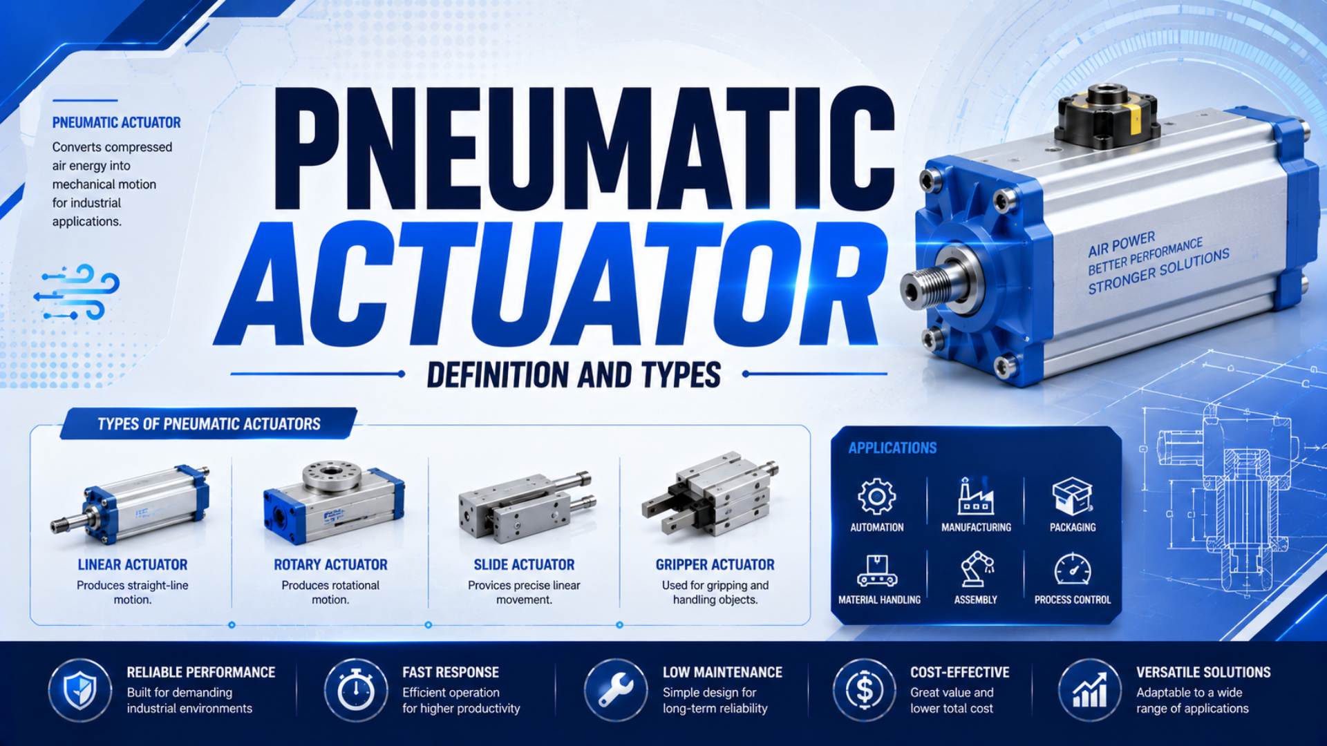
A pneumatic actuator is a device that converts compressed-air energy into mechanical motion. The output may be straight-line travel, limited-angle rotation, gripping, clamping, stopping, or another defined machine action. A pneumatic cylinder is one type of pneumatic actuator, not a synonym for the entire actuator category.
This guide is a terminology and classification reference. It helps engineers and buyers name the right actuator family before discussing bore, stroke, torque, jaw travel, mounting, sensors, or valve flow. For operating physics and detailed sizing, use the broader guide to how pneumatic actuators work.
Key Takeaways
- SMC groups pneumatic actuators into 7 practical families, not only linear, rotary, and rodless types.
- ISO 15552 covers detachable-mounting cylinders with 32-320 mm bores and a 1,000 kPa maximum rated pressure.
- Select the motion and load path first; size the exact actuator only after pressure, speed, control, and environment are defined.
What Is a Pneumatic Actuator?
Festo describes pneumatic cylinders as compressed-air motion components and publishes a representative cylinder speed range from 10 mm/s to 3 m/s (Festo, accessed 2026). A pneumatic actuator is therefore defined by its energy input and mechanical output, not by one body shape or speed class.
Compressed air enters one or more working chambers. Pressure acts on a piston, vane, diaphragm, rack, or similar element, and the mechanism transfers that force to a rod, carriage, shaft, jaw, or clamp arm. A directional valve controls which chamber receives pressure and which chamber exhausts.
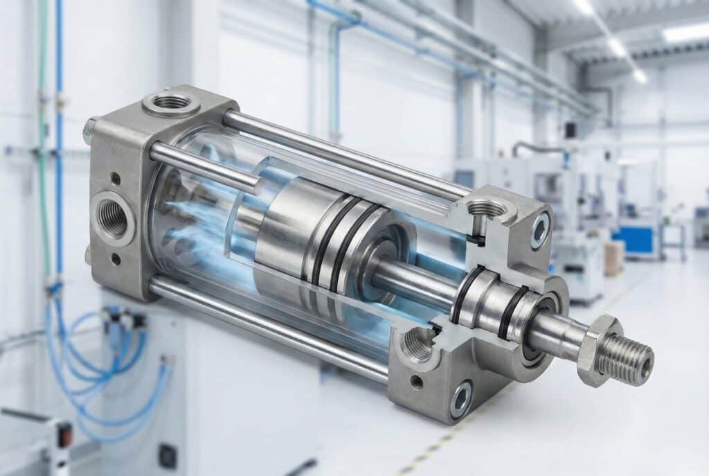
A cutaway linear cylinder illustrates one pneumatic actuator mechanism: pressure acts on a piston and the rod transfers the resulting motion to the machine.
Three related terms should stay separate:
| Term | Practical meaning | Example |
|---|---|---|
| Actuator | Device that converts supplied energy into mechanical action | Pneumatic gripper, rotary actuator, air cylinder |
| Pneumatic drive | Broader engineering term for an air-powered motion device or drive assembly | Guided drive with cylinder, bearings, sensors, and cushioning |
| Pneumatic cylinder | Actuator that uses a pressure chamber and piston, diaphragm, or bellows to create motion | Rod cylinder, rodless cylinder, stopper cylinder |
A valve that directs air is normally a control component, not the machine’s motion actuator. A process-valve package can create confusion because its air-powered unit is also called the valve actuator. Name both items: the solenoid valve controls air, while the pneumatic actuator moves the process-valve stem or shaft.
For a narrower explanation of the parent-child relationship, see whether all cylinders are actuators.
What Are the Main Pneumatic Actuator Types?
SMC organizes its pneumatic actuator range into 7 named families: linear, guided, gripper, rotary, rodless, clamp, and specialty actuators (SMC USA, accessed 2026). That taxonomy is more useful than a three-type list because it distinguishes output motion from the mechanism that supports or contacts the load.
These categories can overlap in construction. A guided slide may contain a conventional piston cylinder. A rodless actuator may include an integrated guide. A gripper may use a wedge, cam, rack, or small rotary mechanism internally. Classification should follow the output delivered to the machine, then note the internal mechanism as a second level.
This two-level description prevents ambiguous RFQs. “Rodless cylinder” describes the air-to-carriage mechanism, but “guided rodless actuator” also states how the external load is supported. Likewise, “rotary actuator” identifies the output, while “rack-and-pinion” identifies how pressure produces torque.
Linear, Guided, and Rodless Actuator Boundaries
ISO 15552:2018 covers detachable-mounting pneumatic cylinders with 32-320 mm bores and a maximum rated pressure of 1,000 kPa, or 10 bar (ISO, confirmed 2025). It standardizes selected mounting and accessory dimensions; it does not assign every linear actuator the same load, speed, life, or side-load capacity.
Rodded linear cylinders
A rodded cylinder transfers piston motion through a rod. Single-acting versions use air for one working direction and a spring or external force for return. Double-acting versions route air to either side of the piston, so both extension and retraction are pressure-driven. Learn the detailed tradeoffs in the single-acting and double-acting cylinder comparison.
Guided actuators
A guided actuator combines pneumatic thrust with guide rods, bearings, or a slide mechanism. The guide resists rotation and specified transverse loads or moments. Capacity is still model-specific. “Guided” isn’t permission to ignore the load center, stroke, speed, bearing type, or combined-moment limits.
Rodless actuators
A rodless actuator moves an external carriage along the cylinder body without a projecting piston rod. SMC separates magnetically coupled and mechanically joined rodless designs (SMC USA, accessed 2026). Both can reduce the clearance required beyond the stroke, but their sealing, coupling, guidance, and allowable-load behavior differ.
| Linear family | Output connection | Best reason to consider it | Main boundary to verify |
|---|---|---|---|
| Rodded cylinder | Piston rod | Simple axial push or pull | Rod clearance, buckling, alignment, external guidance |
| Guided actuator | Tool plate or guided rod assembly | Controlled orientation and stated moment capacity | Guide rating by axis, load offset, stroke, speed |
| Rodless actuator | External carriage | Long travel in a shorter installation envelope | Coupling force, carriage load, sealing, guide configuration |
What if the application needs a 1.5 m transfer? That length alone doesn’t select a rodless unit. Check load mass, center of gravity, moment direction, speed, cushioning, coupling margin, mounting straightness, and contamination exposure. The dedicated rodless actuator guide covers those branch-specific checks.
Rotary, Gripper, Clamp, and Specialty Actuator Roles
Festo lists pneumatic rotary drives with swivel angles up to 270 degrees, while SMC offers pneumatic grippers with 2, 3, or 4 fingers in different product families (Festo; SMC USA, accessed 2026). These outputs require torque, inertia, grip, or holding checks rather than cylinder bore alone.
Rotary actuators
Rotary actuators create limited-angle shaft or table motion. Common mechanisms include rack-and-pinion and vane designs. Select them using required torque through the motion, rotation angle, load inertia, acceleration, deceleration, end-stop energy, backlash or angular play, shaft loads, and mounting orientation. A pneumatic air motor, which can rotate continuously, is a different device.
Use the pneumatic rotary actuator guide when the job is indexing, flipping, turning a valve, or moving a lever.
Pneumatic grippers
Grippers use jaws or fingers to hold a workpiece. Parallel jaws suit many prismatic parts, angular jaws open through an arc, and concentric designs center round parts. Required grip force depends on part mass, acceleration, orientation, friction, jaw length, contact geometry, and the consequence of pressure loss. The pneumatic gripper type guide develops this selection branch.
Clamps and specialty units
Pneumatic clamps hold a workpiece or fixture through a direct, swing, toggle, or application-specific mechanism. Specialty actuators include stopper cylinders, bellows, diaphragm units, multi-position cylinders, tandem or high-force arrangements, and products adapted for heat, washdown, cleanroom, or corrosion exposure.
Don’t force every air-powered mechanism into the “standard cylinder” branch. If the machine’s real output is holding, centering, limited-angle rotation, compliant lifting, or conveyor stopping, selecting the purpose-built family usually makes the load path and failure state easier to define.
How Should You Select a Pneumatic Actuator Family?
ISO 4414:2010 addresses significant pneumatic-system hazards and covers design, construction, modification, installation, adjustment, maintenance, reliable operation, energy efficiency, and environment (ISO, confirmed 2021). Actuator selection should therefore begin with the complete machine function and risk controls, not a catalog photograph or nominal pressure alone.
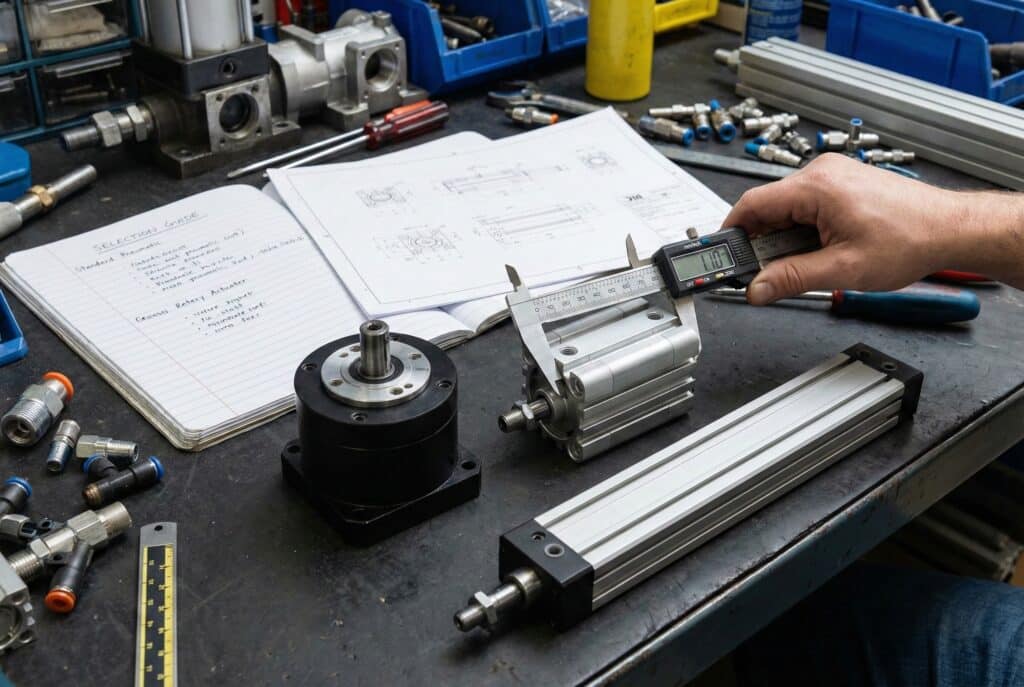
A useful actuator comparison records the required output, load geometry, mounting envelope, control method, and operating environment before a series is selected.
Use this sequence:
- Define the output. Record linear stroke, rotation angle, jaw travel, clamp path, or required holding action.
- Map the load. Include force or torque, mass, center of gravity, friction, inertia, acceleration, gravity direction, side loads, and moments.
- Set the duty. Record cycle rate, dwell time, expected life target, cushioning needs, and allowable impact or vibration.
- Use real pressure and flow. Specify the minimum pressure at the actuator during motion, valve flow data, tube size and length, and exhaust restrictions.
- Choose the control behavior. Define single or double acting, valve function, sensors, intermediate-position needs, speed control, and response after electrical or air-supply loss.
- Check the environment. State temperature, dust, moisture, washdown, chemicals, corrosion, cleanroom, food-zone, and hazardous-area requirements.
- Verify interfaces. Match mounting dimensions, port threads, rod end or shaft, sensor grooves, cushioning, accessories, and maintenance clearance.
In our experience with application reviews, the most useful first drawing is often a simple load-path sketch. It shows where the actuator pushes, where the load is guided, and how far the center of gravity sits from the support. That sketch exposes side loads and moments that a bore-and-stroke request can hide.
Is pneumatic always the right technology? No. If the axis needs many programmable positions, tightly controlled velocity, high stiffness at standstill, or detailed motion feedback, compare the pneumatic family with the electric-actuator selection guide.
What Information Belongs in a Pneumatic Actuator RFQ?
ISO 15552 standardizes interchangeability dimensions only within its 32-320 mm, 1,000 kPa cylinder scope; it does not guarantee equal force, speed, cushioning, seals, sensors, or service life across brands (ISO, confirmed 2025). A replacement RFQ must document operating requirements and interfaces beyond the standard name.
Send the following data:
| RFQ field | Information to provide |
|---|---|
| Actuator function | push, pull, guide, rotate, grip, clamp, stop, or position |
| Motion | stroke, angle, jaw travel, direction, end positions |
| Load | force or torque, mass, center of gravity, inertia, side load, moments |
| Operating conditions | minimum dynamic pressure, speed, cycle rate, dwell, expected duty |
| Control | valve function, sensor type, intermediate positions, fail state |
| Mechanical interface | mounting, rod end, shaft, carriage, port, overall envelope |
| Environment | temperature, contamination, washdown, chemicals, corrosion, area approval |
| Existing unit | manufacturer, complete model code, nameplate, drawing, photos, fault history |
| Acceptance criteria | travel, force or torque, cycle time, leakage, repeatability, inspection record |
“Direct replacement” should mean the compared items are listed and accepted. Matching a mounting pattern is useful, but it doesn’t prove equal allowable moments, cushion energy, sensor behavior, temperature range, seal compatibility, or certification.
For a generic actuator definition, the words “linear” or “rotary” may be enough. For a purchase order, they aren’t. Include the complete configured part number and the application conditions that decide performance.
Pneumatic Actuator Definition and Types FAQs
SMC’s 7-family actuator taxonomy and ISO 15552’s 32-320 mm cylinder scope answer different questions: one classifies machine outputs, while the other defines selected interchangeability dimensions (SMC USA; ISO, accessed 2026). These FAQs keep category, mechanism, standard, and application limits separate.
What is the simplest pneumatic actuator definition?
A pneumatic actuator converts compressed-air energy into mechanical action. The output can be linear motion, limited-angle rotation, gripping, clamping, or another machine function. A directional valve usually controls chamber pressure and exhaust, but the valve itself is not the motion actuator unless the term refers to an air-powered process-valve actuator.
What are the main types of pneumatic actuators?
SMC groups pneumatic actuators into linear, guided, gripper, rotary, rodless, clamp, and specialty families. These categories describe the output delivered to the machine. A second label can identify the internal mechanism, such as single acting, double acting, rack-and-pinion, vane, magnetic coupling, or mechanical coupling.
Is a pneumatic cylinder the same as a pneumatic actuator?
A pneumatic cylinder is a pneumatic actuator type, but the terms aren’t fully interchangeable. “Actuator” is the parent category. It also includes rotary actuators, grippers, clamps, and specialty mechanisms. Use “cylinder” when the selected device actually uses a cylinder mechanism, and add the output and construction details needed for identification.
Does ISO 15552 make pneumatic cylinders interchangeable?
ISO 15552 establishes selected basic, mounting, and accessory dimensions for detachable-mounting cylinders with 32-320 mm bores and a maximum rated pressure of 1,000 kPa. Dimensional conformity can support interchangeability, but it does not prove identical force, cushioning, sensor, seal, speed, load, environmental, or service-life performance.
Which pneumatic actuator type is best for long strokes?
A rodless actuator can reduce the external clearance needed for long linear travel because no piston rod projects beyond the body. It isn’t automatically the best choice. Compare carriage load and moments, guide capacity, coupling margin, sealing method, speed, cushioning, mounting straightness, contamination, maintenance access, and the exact manufacturer’s configured limits.
Sources and technical references
- ISO. ISO 15552:2018. Scope for detachable-mounting pneumatic cylinders, 32-320 mm bores, and 1,000 kPa maximum rated pressure. Confirmed 2025.
- ISO. ISO 4414:2010. General rules and safety requirements for pneumatic fluid power systems and components.
- Festo. Pneumatic cylinders. Cylinder definitions, product families, representative speed range, and rotary-drive information. Accessed 2026-07-26.
- SMC USA. Pneumatic actuators, rodless actuators, and grippers. Category, mechanism, and product-family descriptions. Accessed 2026-07-26.
- AutomationDirect. What is a Pneumatic Cylinder?. Video demonstrating the linear-cylinder branch. Accessed 2026-07-26.