

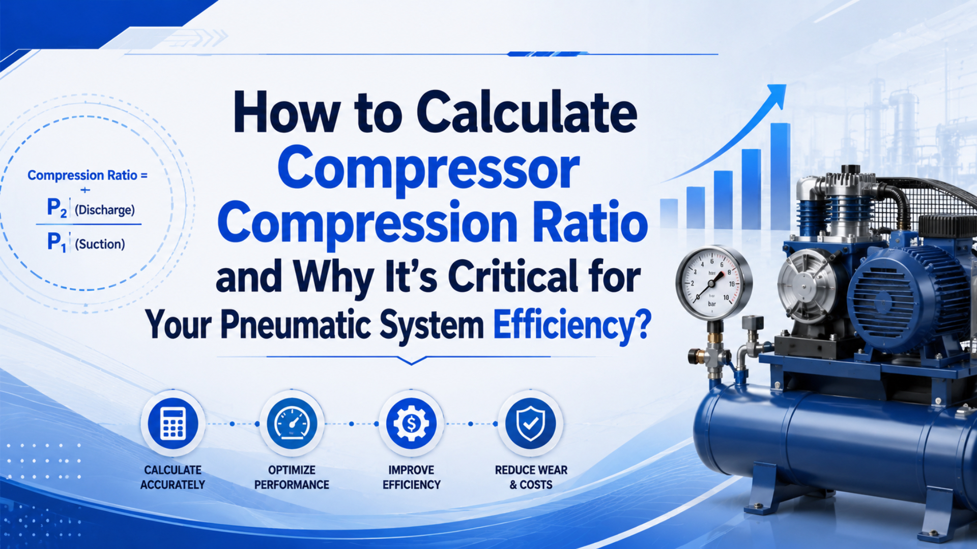
Compressor compression ratio compares discharge absolute pressure with suction absolute pressure. For a plant compressor taking in atmospheric air and delivering 100 PSIG at sea level, the ratio is (100 + 14.7) / 14.7 = 7.8:1. That number matters because it drives heat, power, stage selection, and whether the compressor curve matches the installation.
The most common mistake is using gauge pressure in the formula. A shop gauge at the compressor inlet often reads 0 PSIG, but the compressor is not pulling from zero absolute pressure. It is pulling from local atmosphere. At sea level, NOAA lists standard sea-level pressure near 1013.25 hPa, commonly treated as about 14.7 psi (NOAA JetStream, 2026).
Use the ratio as a sorting number, not a solo purchasing rule. A 7.8:1 calculation tells you the thermodynamic job, but it does not tell you whether a dryer is undersized, a receiver is too small, or a filter is stealing pressure at the point of use. We normally pair it with three field measurements: suction pressure at the compressor, discharge pressure after treatment, and actuator pressure during motion. For example, a machine can show a reasonable compressor ratio and still starve a rodless axis because a regulator, coiled hose, or muffler drops pressure only during acceleration. If those numbers disagree, the ratio is still useful, but it points to a system problem rather than a compressor-only problem.
Key Takeaways
- Use absolute pressure:
compression ratio = discharge PSIA / suction PSIA.- At 100 PSIG and sea-level suction, ratio is about 7.8:1.
- DOE says every 2 psi of extra discharge pressure near 100 psig can add about 1.6-2% total energy use.
What Is Compressor Compression Ratio?
Compressor compression ratio is discharge absolute pressure divided by suction absolute pressure. Engineering ToolBox defines it as CR = p_d / p_s, using discharge and suction pressure in absolute units (Engineering ToolBox, 2026). In compressed-air work, that means PSIA or bara, not PSIG or barg.
Put simply, the ratio tells you how hard the compressor is squeezing the inlet air. A 7.8:1 ratio is not just “100 psi.” It means each unit of inlet absolute pressure is raised to about 7.8 units of discharge absolute pressure before losses and controls enter the picture.
In our experience, compression-ratio errors usually start in spreadsheets, not in the compressor room. Someone labels a column “pressure,” mixes 100 PSIG with 14.7 PSIA, and the calculated ratio looks harmless. The machine then runs hot, the dryer sees more moisture load, and the pneumatic actuator still blames the compressor.
| Term | Use this value | Example at sea level |
|---|---|---|
| Suction absolute pressure | Local atmosphere plus suction gauge pressure | 0 PSIG + 14.7 = 14.7 PSIA |
| Discharge absolute pressure | Gauge discharge plus local atmosphere | 100 PSIG + 14.7 = 114.7 PSIA |
| Compression ratio | Discharge absolute / suction absolute | 114.7 / 14.7 = 7.8:1 |
| Wrong shortcut | Gauge discharge / gauge suction | 100 / 0, impossible |
For actuator selection, use gauge pressure when you calculate cylinder force against a vented exhaust side. For compressor ratio, receiver air mass, vacuum, gas-law checks, and altitude correction, use absolute pressure. If that distinction feels fussy, this companion article on absolute pressure in pneumatic systems is the right pre-read.
How Do You Calculate Compressor Compression Ratio With Absolute Pressure?
Start by converting every pressure value to absolute pressure. The standard atmosphere is 101.325 kPa, or about 14.696 psi, in common engineering references (Engineering ToolBox, 2026). This keeps sea-level and high-altitude jobs comparable before you read compressor curves.
The calculation is short:
Compression ratio = P_discharge_absolute / P_suction_absolute

P_absolute = P_gauge + P_atmosphere

Example at sea level:
P_discharge_absolute = 100 PSIG + 14.7 = 114.7 PSIA
P_suction_absolute = 0 PSIG + 14.7 = 14.7 PSIA
Compression ratio = 114.7 / 14.7 = 7.8:1
What if the compressor draws through a dirty inlet filter and the inlet is slightly below atmosphere? Then suction absolute pressure is lower, so ratio rises. That detail can change discharge temperature and performance even when the discharge gauge has not moved.
Need a metric version? At 7 barg discharge with 1.013 bar atmospheric suction, the ratio is (7 + 1.013) / 1.013 = 7.91:1. The formula is the same. Only the units change.
Altitude Correction and Gauge-Pressure Mistakes
Altitude changes suction absolute pressure, so it changes compression ratio at the same gauge discharge setting. NASA Glenn notes that air pressure and density decrease as altitude increases (NASA Glenn, 2026). A 100 PSIG compressor ratio is lower at sea level than it is at 5,000 ft.
At sea level, a 100 PSIG discharge with atmospheric suction is about 7.8:1. Near 5,000 ft, local atmospheric pressure is commonly estimated around 12.2 PSIA under standard-atmosphere conditions. The same 100 PSIG discharge becomes (100 + 12.2) / 12.2 = 9.2:1.
That is a large difference. The gauge still says 100 PSIG, but the compressor is working against a higher pressure ratio because the inlet absolute pressure is lower. How many compressor problems are really pressure-reference problems? More than most teams want to admit.
| Installation condition | Atmosphere used | 100 PSIG discharge absolute | Compression ratio |
|---|---|---|---|
| Sea level | 14.7 PSIA | 114.7 PSIA | 7.8:1 |
| 5,000 ft standard atmosphere | 12.2 PSIA | 112.2 PSIA | 9.2:1 |
| 10,000 ft standard atmosphere | 10.1 PSIA | 110.1 PSIA | 10.9:1 |
When we review compressor sizing for machines shipped across regions, the safest habit is to write both pressure references in the RFQ: 100 PSIG discharge, atmospheric suction, site elevation 5,000 ft. That one line helps the compressor supplier pick the right curve and keeps the actuator team from treating a mountain site like a coastal site.
What Ratio Range Is Practical for Pneumatic Systems?
Many factory pneumatic systems end up around 7:1 to 9:1 when they deliver roughly 90-115 PSIG from atmospheric suction at sea level. DOE’s compressed-air sourcebook warns that extra pressure near 100 psig can increase total energy use by about 1.6-2% for every 2 psi increase when artificial demand is included (DOE Sourcebook, 2022).
There is no single universal “best” ratio. Compressor type, controls, inlet pressure, elevation, intercooling, air treatment, and point-of-use pressure all matter. The practical rule is narrower: keep the compressor ratio only as high as the end uses require after pressure drop has been fixed.
For most pneumatic actuators, the better question is not “Can the compressor make more pressure?” It is “Does the actuator receive enough pressure during motion?” The answer belongs at the cylinder port, not only at the compressor discharge gauge.
| Pneumatic need | Common pressure question | Compression-ratio implication |
|---|---|---|
| Standard air cylinders | Can the cylinder make force at measured port pressure? | Avoid raising plant pressure before checking bore, load, tubing, and valve flow |
| Rodless cylinders and slides | Is motion stable over a long stroke? | Check local pressure drop, storage, regulator capacity, and exhaust restriction |
| High-force clamps | Is a larger bore cheaper than higher pressure? | Higher pressure raises ratio and leakage demand across the whole system |
| High-altitude sites | Was local atmosphere included? | Same PSIG can mean a higher compression ratio |
For cylinder-specific pressure selection, connect this article to working pressure of an air cylinder. Keep this page focused on the compressor side of the decision.
When Should You Use Multi-Stage Compression?
Use multi-stage compression when the total ratio creates too much discharge temperature, poor efficiency, or reliability risk for one stage. NASA’s isentropic-flow reference shows pressure, temperature, and density are linked during compressible gas processes (NASA Glenn, 2021). In compressor work, a higher pressure ratio generally means more heat to manage.
If one stage tries to do too much work, discharge temperature rises and volumetric efficiency suffers. Intercooling between stages removes heat, reduces the work required by the next stage, and gives moisture a chance to condense before the air moves forward.
The equal-ratio rule is a useful first pass:
Stage ratio = total compression ratio^(1 / number of stages)

Example:
Total ratio = 9:1
Two stages = sqrt(9) = 3:1 per stage
Three stages = 9^(1/3) = 2.08:1 per stageTreat exact compressor life and maintenance percentages cautiously unless they come from measured site records. A stronger decision ties compressor selection to measurable temperature, pressure ratio, compressor curves, and service history.
How Does Compression Ratio Change Energy Cost?
Compression ratio raises energy cost because higher discharge pressure takes more compressor work and often increases artificial demand. DOE gives a practical rule near 100 psig: every 2 psi increase in discharge pressure adds about 1% compressor energy, plus 0.6-1.0% from unregulated demand, for about 1.6-2% total energy increase (DOE Sourcebook, 2022).
That rule is not a pressure-ratio formula, but it is the field number buyers remember. A plant that raises discharge pressure from 100 to 110 psig may add roughly five increments of that 2 psi rule. If unregulated demand is present, the energy penalty can be meaningful before anyone notices better actuator behavior.
Leaks make the same problem worse. ENERGY STAR says compressed-air leaks often waste as much as 20-30% of compressor output and can cause fluctuating system pressure (ENERGY STAR, 2000). Raising pressure to feed leaks is a very expensive way to avoid finding them.
One practical way to frame the cost is to separate required pressure from purchased pressure. Required pressure is what the actuator, valve, or tool needs while doing useful work. Purchased pressure is the compressor discharge setting plus every extra psi added to cover dirty filters, undersized tubing, leaks, or uncertain troubleshooting. Compression ratio follows purchased pressure. If the plant buys 110 PSIG but the work device only needs 92 PSIG at the port, the gap is not a productivity feature. It is an investigation list, with no benefit at the actuator.
For broader system-level actions, link to energy conversion efficiency in pneumatic systems. The quick lesson here is simple: if the ratio is high because the plant pressure is high, first prove the end use needs that pressure.
Field Checklist Before You Raise Compressor Pressure
CAGI says a well-designed compressed-air system should have no more than 10% pressure drop between compressor discharge and any point of use (CAGI Pressure Drop Technical Brief, 2026). If a cylinder is weak, measure point-of-use pressure under flow before changing compressor setpoints.
Use this order when the ratio looks high or the machine is short on pressure:
- Measure compressor suction pressure, discharge pressure, and site elevation.
- Convert both suction and discharge to absolute pressure before calculating anything.
- Calculate compression ratio from absolute values, and write the formula in the report so reviewers can see the reference pressure.
- Log point-of-use pressure while the pneumatic actuator moves, not only while it sits idle.
- Check filter differential pressure.
- Review regulator size, valve flow, tubing length, fittings, mufflers, and exhaust restrictions as one air path.
- Find leaks during non-production hours and quantify leak load; ENERGY STAR’s 20-30% warning is too expensive to ignore.
- Compare the corrected requirement with compressor performance curves. If the ratio is still high, consider staged compression, local storage, or a larger actuator bore before raising the whole header.
The ordering matters. If you raise the compressor first, every leak and unregulated blowoff gets a raise too. If you measure the actuator first, you may find a clogged filter, undersized hose, or poor valve choice. That’s a cheaper fix than buying compression ratio you didn’t need.
If the failure appears only during another station’s cycle, read pressure fluctuations in pneumatic systems. If the issue is flow-to-pressure confusion, use air flow to pressure conversion as the companion article.
FAQs About Compressor Compression Ratio
The questions below cover the calculation errors that most often create wrong compressor decisions. CAGI’s pressure-drop FAQ repeats two useful field rules: keep pressure drop near or below 10%, and expect about 1% more compressor power for every 2 psig of excess operating pressure in positive displacement systems (CAGI Pressure Drop FAQ, 2026).
What is the formula for compressor compression ratio?
The formula is compression ratio = discharge absolute pressure / suction absolute pressure. Engineering ToolBox defines the ratio with both pressures in absolute units. For 100 PSIG discharge and atmospheric sea-level suction, use 114.7 / 14.7, giving about 7.8:1, not 100 / 0.
Why can’t I calculate compressor ratio with gauge pressure?
Gauge pressure uses local atmosphere as zero, while a compressor with an atmospheric inlet still has about 14.7 PSIA suction at sea level. Dividing by gauge suction can create an impossible ratio. Use absolute pressure any time the calculation compares two gas states, such as suction and discharge.
How does altitude affect compressor compression ratio?
Altitude lowers suction absolute pressure. At 100 PSIG discharge, sea-level atmospheric suction gives about 7.8:1, while a standard-atmosphere estimate near 5,000 ft gives about 9.2:1. The discharge gauge may look unchanged, but the compressor sees a higher pressure ratio because inlet absolute pressure is lower.
Does a higher compression ratio always mean better pneumatic performance?
No. Higher ratio can support higher discharge pressure, but it also increases compressor work, heat, leakage demand, and air-treatment load. DOE says every extra 2 psi near 100 psig can add about 1.6-2% total energy use when artificial demand is included. Fix local pressure drop first.
When is multi-stage compression better than one-stage compression?
Multi-stage compression is better when one stage would create excessive discharge temperature, poor efficiency, or reliability risk. A first-pass rule is to split total ratio evenly: a 9:1 total ratio becomes roughly 3:1 per stage in a two-stage compressor. Final selection should still use manufacturer curves.
What should I send in an RFQ for compressor ratio review?
Send required point-of-use pressure, flow demand, duty cycle, site elevation, inlet restrictions, air-treatment equipment, pressure-drop measurements, leak estimate, and the actuator pressure measured during motion. Include both PSIG and PSIA where possible. That prevents the compressor supplier and pneumatic designer from solving different problems.
Sources and Retrieval Notes
-
Engineering ToolBox: Compressed Air vs. Free Air - Compression Ratio. Retrieved 2026-06-04. Supports the absolute-pressure compression-ratio formula.
-
Engineering ToolBox: Pressure. Retrieved 2026-06-04. Supports standard atmospheric pressure values.
-
NOAA JetStream: Air Pressure. Retrieved 2026-06-04. Supports standard sea-level pressure context.
-
NASA Glenn: Air Properties Definitions. Retrieved 2026-06-04. Supports altitude effects on air pressure and density.
-
NASA Glenn: Isentropic Flow Equations. Retrieved 2026-06-04. Supports pressure, temperature, and density relationships in compressible gas processes.
-
U.S. DOE: Improving Compressed Air System Performance, Third Edition. Retrieved 2026-06-04. Supports the 2 psi pressure-increase energy rule and artificial-demand penalty.
-
CAGI: Pressure Drop Technical Brief. Retrieved 2026-06-04. Supports the 10% pressure-drop design target.
-
CAGI: Pressure Drop FAQs. Retrieved 2026-06-04. Supports the pressure-drop target and 2 psig excess-pressure guideline.
-
ENERGY STAR: Minimize Compressed Air Leaks. Retrieved 2026-06-04. Supports leak waste and system-pressure fluctuation statements.