

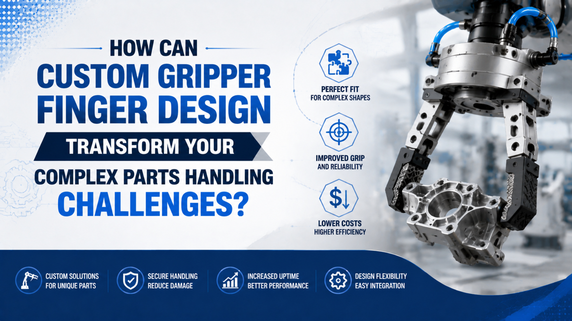
Custom gripper finger design turns the workpiece itself into the starting point for the end effector. Instead of asking a standard jaw to tolerate poor contact, the designer defines safe contact zones, locating features, finger length, grip force, pad material, and release clearance around the real part and fixture.
The result can be a more stable grasp, but custom fingers do not repair an undersized or misapplied gripper. The body still needs enough stroke, force, guide capacity, and pressure margin. The finished tool must also prove that it can hold, release, sense, and recover safely under production conditions.
Key Takeaways
- SMC recommends 10 to 20 times workpiece weight as an initial two-finger gripper selection range.
- Check force at the real contact distance, not at the jaw face.
- Form-closure features can reduce dependence on friction.
- Validate every part extreme, motion direction, and air-loss state.
What Does Custom Gripper Finger Design Actually Change?
A 2024 Scientific Reports classification divides a robotic gripping system into five major units: coupling, power, clamping, locating, and control (Scientific Reports, 2024). Custom fingers mainly reshape the clamping and locating functions, but their geometry affects every other unit in the assembled end effector.
Custom gripper fingers are the workpiece-specific attachments fixed to a gripper’s moving jaws. The gripper body generates and guides motion. The fingers transfer that motion to defined contact points on the part. Their job may include holding, centering, orienting, supporting, protecting a surface, or clearing a fixture during release.
This distinction prevents an expensive category error. If the jaw path, stroke, or force is wrong, changing the fingertips may not solve the station. If the gripper body fits but flat stock fingers contact a curved, tapered, delicate, or variable part poorly, custom tooling can be the lowest-complexity correction.
Use three drawings before selecting material:
- The workpiece at minimum and maximum permitted dimensions.
- The complete finger envelope in open, first-contact, and closed positions.
- The fixture, robot wrist, guards, sensors, and escape path around the grasp.
In our experience, overlaying those three envelopes exposes the real problem faster than comparing gripper bore sizes. It shows whether the failure comes from contact geometry, insufficient stroke, fixture interference, a long moment arm, or part variation that the finger cannot accommodate.
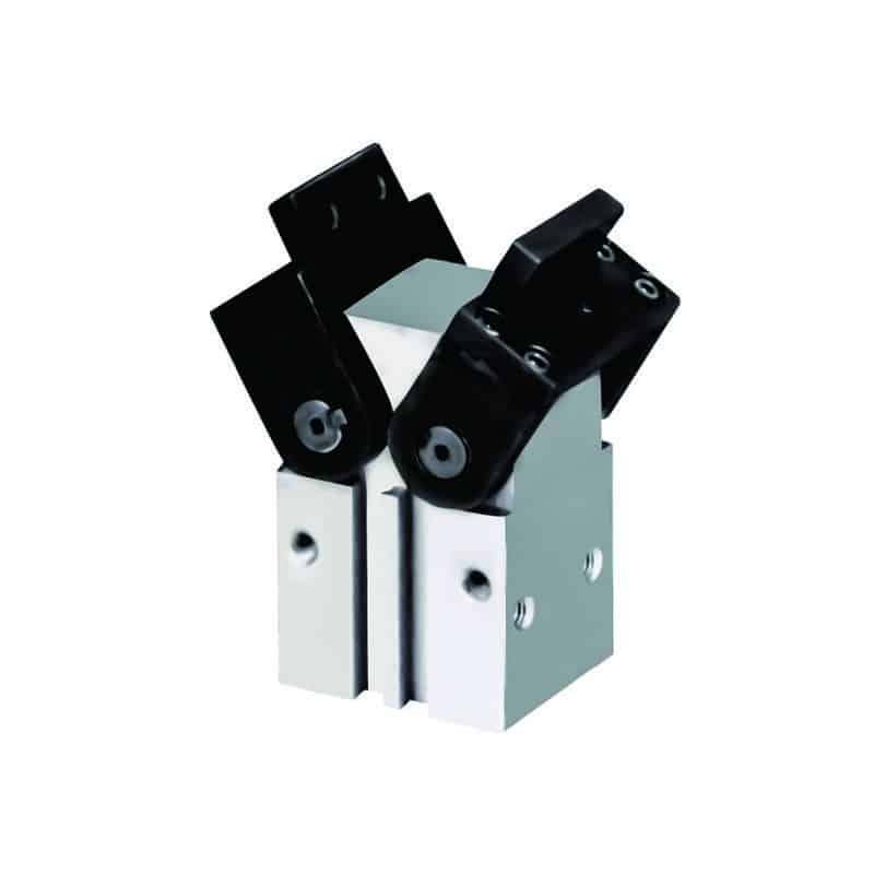
For gripper-body options, start with the broader pneumatic gripper types guide. Use the parallel versus angular gripper comparison when the open and closed paths compete for fixture clearance.
When Should Custom Fingers Use Form-Closure Instead of Friction?
The same 2024 classification separates mechanical fingers into two grasp classes: force-closure and form-closure (Scientific Reports, 2024). A force-closure grasp depends mainly on normal force and friction; a form-closure grasp uses geometry to resist movement. Many reliable custom fingers combine both instead of relying on pressure alone.
Force-closure is a grasp that holds the part mainly through normal force and friction. For example, opposing pads can clamp stable faces when the coefficient of friction remains predictable. Oil, dust, coolant, surface coating, or mold-finish changes can reduce that margin. More clamp force may then mark or distort the part before it creates a reliable grasp.
Form-closure is a grasp that uses geometry to restrain motion through a groove, pocket, step, pin, hook, V-profile, or nest. The feature should locate the workpiece without wedging it so tightly that the gripper cannot release. Prevent a burr or tolerance extreme from carrying the entire load on one sharp edge.
| Part condition | Preferred contact strategy | Design check |
|---|---|---|
| Two stable parallel faces | Friction pads or shallow contour | Conservative friction and contact pressure |
| Round shaft or tube | V-groove, three-point contact, or centering jaws | Diameter range and line-contact stress |
| Tapered or irregular casting | Contoured support plus locating feature | Draft angle, flash, and part variation |
| Delicate cosmetic surface | Large replaceable soft pads | Marking, compression set, and particle shedding |
| Oily machined component | Geometry-assisted restraint | Drainage, cleanability, and release path |
| Part with a safe hole or boss | Internal grip, pin, or hook feature | Edge load, insertion clearance, and extraction |
The best custom finger does not always maximize contact area. It creates enough support to control translation and rotation while leaving dirt relief, tolerance clearance, and a clean release path. A fully matched contour can become a trap when the part carries chips, flash, or dimensional drift.
How Do You Calculate Grip Force Without Crushing the Part?
SMC’s MHS selection guide recommends 10 to 20 times workpiece weight for a two-finger model, 7 to 13 times for three fingers, and 5 to 10 times for four fingers, with added margin for acceleration or impact (SMC MHS, accessed 2026). These are model-selection guides, not universal damage limits.
For a friction grip with n loaded fingers, use this first-pass requirement:
Required normal force per loaded finger = m x (g + a) x S / (mu x n)Where:
| Variable | Meaning |
|---|---|
m |
Workpiece mass in kilograms |
g |
Gravitational acceleration, approximately 9.81 m/s2 |
a |
Acceleration in the load direction, including deceleration |
S |
Application safety factor based on risk and uncertainty |
mu |
Conservative friction coefficient for the actual surface condition |
n |
Number of fingers sharing the friction load |
For example, suppose a 0.8 kg part moves vertically with 4 m/s2 upward acceleration. With two loaded fingers, mu = 0.25, and S = 2, the first-pass requirement is about 44 N per finger. That value still needs three corrections: force at the actual contact distance, pressure during motion, and external load on the jaw guide.
Do not assign a smaller safety factor simply because the part is fragile. Retention margin and damage protection solve different problems. Reduce surface stress with a larger pad, compliant insert, geometry-assisted restraint, slower acceleration, or another grasp location. Then confirm the acceptable force window by testing actual parts.
Average contact pressure is a useful screen:
Average contact pressure = normal force / projected contact areaIt cannot predict every local peak. Edges, ribs, glass flaws, thin walls, pad compression, and misalignment concentrate stress. If part damage matters, record the permitted contact zones and prove the design with the worst material, wall thickness, temperature, and dimensional condition.
Why Do Finger Length, Offset, and Mass Matter?
In SMC’s MHS2 example, the selected gripper produces 92 N per finger at 0.4 MPa and a 20 mm gripping-point distance (SMC MHS, accessed 2026). The same catalog warns that contact beyond its published range adds offset load to the sliding section and can shorten service life.
Finger length changes the tool even when required holding force stays constant. A longer contact distance increases the moment at the jaw guide:
Jaw moment = contact force x distance from jaw reference to contact pointThe catalog force curve and allowable load table must come from the exact gripper model. Do not transfer a 20 mm example or a moment limit from another bore or jaw style. Angular grippers may publish force, torque, or gripping moment at a defined angle. Parallel models commonly publish force per finger against contact distance and pressure.
SMC’s air-gripper precautions also say attachments should be as light and short as possible because long or heavy tooling raises opening and closing inertia (SMC Air Gripper Precautions, accessed 2026). That inertia can produce unstable motion, impact at stroke ends, slower cycles, and additional guide load.
Check all of these before releasing the finger drawing:
- Contact-point distance in the open and closed conditions
- Vertical and lateral offset from the jaw reference
- Finger mass and center of gravity
- External process force transmitted through the part
- Acceleration, deceleration, and emergency-stop load
- Opening and closing impact at the requested cycle rate
- Fastener preload, locating features, and interface stiffness
A long finger is not automatically wrong. It simply makes guide capacity and inertia first-order design inputs. If the moment exceeds the selected body’s limit, shorten the tool, move the grasp, support the part, use a higher-capacity gripper, or divide the load between two grippers.
Finger Materials and Contact Pads for Real Parts
SMC’s current gripper selector lists three dust-cover elastomers, chloroprene, fluororubber, and silicone, plus models with SUS304 fingers (SMC Model Selection, accessed 2026). The range illustrates the rule for custom tooling: select the exact grade and surface system from the environment, load, wear, and contamination requirements.
| Material or contact system | Strong fit | Watch point |
|---|---|---|
| Aluminum alloy | Low moving mass, easy machining, prototypes, moderate loads | Thread wear, coating buildup, chemical exposure |
| Stainless steel | Thin strong features, wear, washdown, heat, corrosion resistance | Higher mass, harder machining, possible part marking |
| PEEK or another engineering polymer | Chemical exposure, electrical isolation, low-mass contact | Grade-specific strength, creep, friction, approval, and cost |
| Urethane or elastomer pad | Friction, cushioning, cosmetic surfaces | Compression set, swelling, temperature, shedding, pad wear |
| Replaceable hardened insert | Small wear feature or repeatable locating edge | Stress concentration and controlled installation |
| Hybrid finger | Stiff metal structure with replaceable soft contact | Bonding, fasteners, cleanability, and spare-pad control |
Victrex reports that PEEK friction varies with velocity, pressure, temperature, lubrication, roughness, and the counterface (Victrex Material Properties Guide, 2020). That is why “PEEK is low friction” is not a complete finger specification. Name the grade, mating surface, load, temperature, cleaning chemical, and required approval.
Surface treatment deserves the same precision. If aluminum is anodized, state the coating type and whether the drawing dimensions apply before or after treatment. Mask locating surfaces or include coating growth in the tolerance scheme. For a soft pad, define hardness, thickness, attachment method, replacement interval trigger, and whether the pad may leave residue.
Treat the contact pad as a wear component, not a permanent property of the gripper. A replaceable insert with a controlled datum lets maintenance restore the original geometry. A bonded pad with no inspection limit can slowly change part position long before it visibly fails.
How Do You Turn CAD Geometry Into a Build-Ready Finger Drawing?
SCHUNK’s FGR workflow predefines the gripper interface so only the workpiece side remains to be configured, and it supplies CAD data for the result (SCHUNK FGR, accessed 2026). That one fixed interface is the right starting point: lock the jaw connection before refining the custom contact profile.
A clean 3D model is not yet a manufacturing specification. The drawing must identify which features locate on the gripper, which features contact the part, and which dimensions can float. If left and right fingers are mirrored rather than identical, give them separate part numbers and inspection views.
Include at least these drawing controls:
| Drawing field | Required definition |
|---|---|
| Gripper interface | Mounting pattern, thread, screw grade, locating shoulder or dowels |
| Datums | Jaw-side primary datum and workpiece-side inspection references |
| Contact geometry | Profile, radii, relief, lead-in, pocket depth, allowed contact band |
| Tolerances | Part extremes, position, symmetry, profile, and assembled jaw spacing |
| Material | Exact alloy, polymer grade, hardness, heat treatment, or pad specification |
| Finish | Roughness, coating, masking, edge break, deburring, and cleanliness |
| Mass properties | Finger mass and center of gravity when the gripper limit requires them |
| Identification | Left/right marking, revision, replaceable-pad code, and traceability |
| Inspection | Gauge method, mating reference, sample part, and acceptance record |
Design relief around dirt, burrs, flash, and nonfunctional surfaces. For example, a fully constrained CAD contour can look perfect but jam when production parts arrive at tolerance limits. Use lead-ins to guide the part, then put the precision contact only where the process needs it.
Before machining, review the tool in the robot or machine assembly. Check the complete swept envelope, wrist payload, tool-center-point shift, fastener access, sensor access, tubing route, and removal path. The pneumatic tubing routing guide helps prevent the end-effector service loop from becoming the next interference.
How Should the Finger Design Integrate With the Gripper and Controls?
Festo’s gripper-sizing workflow asks for three application inputs before recommending products: object mass, surface quality, and gripper-jaw length (Festo Gripper Sizing, accessed 2026). Those inputs connect the part, finger, and gripper body. Controls then have to prove the intended grasp rather than merely command the jaws closed.
A pneumatic gripper is already an actuator. A rodless cylinder may move the entire end effector along a machine axis, but it normally does not create jaw force. Select the gripper body from its jaw path, stroke, effective force at the contact point, guide loads, pressure range, operating frequency, environment, and failure state.
For pneumatic integration, verify dynamic pressure at the valve while the machine cycles. A static gauge upstream can hide losses through the manifold, tubing, fittings, and exhaust. If margin is narrow, use the pressure-drop troubleshooting guide before raising the regulator setting.
Sensing should answer a process question:
- Open sensor: Are the fingers clear for approach or release?
- Closed sensor: Did the mechanism reach its empty closed position?
- Part window: Did the jaws stop within the expected width range?
- Independent part-present sensor: Is the workpiece actually in the intended location?
- Pressure or force signal: Did the clamping event develop the expected response?
A closed switch alone may prove that no part is present. With custom fingers, teach or calculate the valid jaw window for each part variant. Add a timeout and an impossible-state check. If response time matters, compare valve and sensor behavior with the solenoid valve response-time guide.
Speed control matters too. Metering the jaw motion can reduce impact on thin or brittle parts, but an excessively slow close may miss the cycle target or hide a sticky mechanism. Record pressure, jaw state, part signal, and cycle time during validation instead of tuning by sound.
Validation: Prove the Grasp Under Real Conditions
OSHA identifies three end-effector mechanical-failure examples: parts release, gripper-mechanism failure, and power-tool failure (OSHA Robot Systems, accessed 2026). A custom finger validation plan must therefore prove normal handling and defined fault responses. A successful bench pick is only the first test condition.
Test the tool in layers:
- Dimensional inspection: verify jaw interface, finger profile, assembled spacing, and pad location.
- Static grasp: hold minimum, nominal, and maximum part conditions at the planned pressure.
- Direction test: approach and load the part from every production direction.
- Dynamic transfer: run the real acceleration, deceleration, orientation change, and cycle rate.
- Surface test: inspect for marks, chips, deformation, particle transfer, or coating damage.
- Variation test: include tolerance extremes, burrs, oil, dust, temperature, and worn pads where applicable.
- Fault test: simulate missed picks, partial insertion, pressure loss, sensor failure, and emergency stop.
- Recovery test: verify safe release, restart, rehoming, and operator intervention procedures.
- Wear test: define the inspection feature and limit that trigger finger or pad replacement.
ISO 4414:2010 is a 38-page standard covering general rules and safety requirements for pneumatic systems and components, and ISO confirmed it remains current in 2021 (ISO 4414, 2021). Use the machine risk assessment to define the safe state; a normal gripper sensor is not automatically a safety-rated function.
Define acceptance in measurable terms. “Handles the part reliably” is not a test. A useful criterion names the part revision, dimensional condition, surface state, orientation, motion profile, pressure range, cycle count, allowable marking, jaw-position window, and response after air loss.
If a dropped part can injure someone or damage equipment, do not depend only on trapped air. The design may need spring retention, a mechanical latch, controlled lowering, guarding, a secondary support, or another protective measure established by the risk assessment.
What Should Go Into a Custom Finger RFQ?
SMC’s MHS selection procedure uses two explicit steps, gripping force and gripping point, while Festo adds object mass, surface quality, and jaw length to its sizing inputs (SMC, accessed 2026; Festo, accessed 2026). A useful RFQ supplies all five before asking for a finger price.
Send the full application package:
| RFQ field | What to provide |
|---|---|
| Workpiece | 3D model, drawing, mass, center of gravity |
| Variation | Dimension extremes, burrs, flash, deformation |
| Contact | Allowed and forbidden zones, finish, hardness, cleanliness, damage limit |
| Grip | Internal or external, friction or form closure, required orientation |
| Motion | Acceleration, speed, direction changes, cycle rate |
| Gripper | Exact model, jaw interface, stroke, force curve, gripping-point limit |
| Finger | Length, offset, material, removable-pad requirement |
| Pneumatics | Dynamic pressure, valve, tubing, exhaust, speed controls |
| Detection | Open, closed, part-present, width window, pressure, or force feedback |
| Environment | Temperature, oil, washdown, dust, chemicals, cleanroom needs |
| Safety | Air-loss state, emergency-stop behavior, dropped-part consequence |
| Validation | Samples, test quantity, measurement method, acceptance criteria |
Photos help, but drawings prevent interpretation errors. Mark the desired contact areas on one image and the forbidden areas on another. Include the open and closed fixture views. If the gripper model has not been chosen, state that clearly so the review can separate body selection from finger design.
Jason Tan prepared this guide from a manufacturing and inspection perspective. The Jason Tan author page and About Bepto provide the engineering background behind this technical library.
For a design review, send the part model, gripper data, motion profile, pressure, environment, and acceptance requirements through the technical contact page.
FAQs About Custom Gripper Finger Design
SMC’s published two-finger selection range starts at 10 to 20 times workpiece weight, but its precautions separately require a valid gripping point and short, light attachments (SMC MHS, accessed 2026; SMC Precautions, accessed 2026). These answers keep force, geometry, and validation in the same decision.
Can custom fingers be added to an existing pneumatic gripper?
Often, yes, if the exact gripper has a documented attachment interface and enough stroke, force, gripping-point range, and guide capacity. Confirm mounting holes, locating features, screw torque, open and closed clearance, finger mass, and sensors. Treat an undocumented or worn jaw interface as a redesign risk, not a machining shortcut.
Does more grip force make a fragile part safer to handle?
No. More normal force increases friction margin but can also raise contact stress, deformation, and marking. First calculate the retention requirement, then enlarge or soften the contact, add geometry-assisted restraint, reduce acceleration, or move the grasp. Test the resulting force window on worst-condition production parts rather than adopting a generic delicate-part safety factor.
How long can a custom gripper finger be?
There is no universal length. Use the exact model’s gripping-point range, force curve, allowable external load, and moment limits. SMC warns that excessive contact distance adds offset load to the sliding section. Also include finger mass, center of gravity, acceleration, impact, and the closed and open contact positions.
Should I use aluminum, stainless steel, PEEK, or urethane?
Choose from load, mass, temperature, chemicals, wear, cleanliness, surface marking, and approval requirements. Aluminum is easy to machine; stainless supports thin durable features; engineering polymers can isolate or protect; urethane adds compliance and friction. Specify the exact grade, finish, hardness, attachment method, and replacement limit instead of naming only a material family.
How do I verify that the finger will not damage the part?
Define allowed contact zones and a measurable damage limit. Check average pressure, then test actual tolerance extremes under production acceleration, orientation, pressure, temperature, and surface conditions. Inspect for marks, cracks, deformation, particles, and positional shift. Repeat after pad wear or contamination, because a clean first-off sample does not represent long-term production.
Sources
Nine primary technical sources plus one official video support this guide. SMC provides force, gripping-point, and attachment precautions; SCHUNK and Festo document finger and gripper configuration inputs; Scientific Reports supplies the five-unit gripping-system model; Victrex covers grade-dependent tribology; ISO and OSHA establish pneumatic and robot-hazard context. All web sources were checked on 2026-07-17.
-
Scientific Reports, New Classification of Industrial Robotic Gripping Systems for Sustainable Production, 2024: Supports the five-unit gripping-system model, force-closure and form-closure distinction, and part-to-system design approach.
-
SMC, MHS Series Air Gripper Catalog, accessed 2026: Supports weight-multiple guidance, the friction formula, the 92 N example, gripping-point curves, and offset-load warnings.
-
SMC, Air Gripper Precautions, accessed 2026: Supports short and light attachment guidance, opening-width checks, screw torque, gripping-point limits, and drop-prevention requirements.
-
SMC, Air Gripper Model Selection Software, accessed 2026: Supports gripper configuration fields and selectable material examples.
-
SCHUNK, FGR Customizable Gripper Fingers, accessed 2026: Supports predefined gripper interfaces, workpiece-side customization, CAD output, and finger identification.
-
Festo, Gripper Sizing, accessed 2026: Supports the use of object mass, surface quality, and jaw length as gripper-selection inputs.
-
Victrex, Material Properties Guide, 2020: Supports grade- and condition-dependent friction, wear, chemical resistance, and thermal-property context for PEEK.
-
ISO, ISO 4414:2010, confirmed 2021: Supports pneumatic-system safety, reliable-operation, maintenance, and intended-use context.
-
OSHA, Technical Manual: Industrial Robot Systems and Industrial Robot Applications, accessed 2026: Supports parts-release and gripper-mechanism-failure hazard context.
-
SMC Video Library, Air Grippers, accessed 2026: Verifies the official JMHZ2 demonstration video embedded above.