

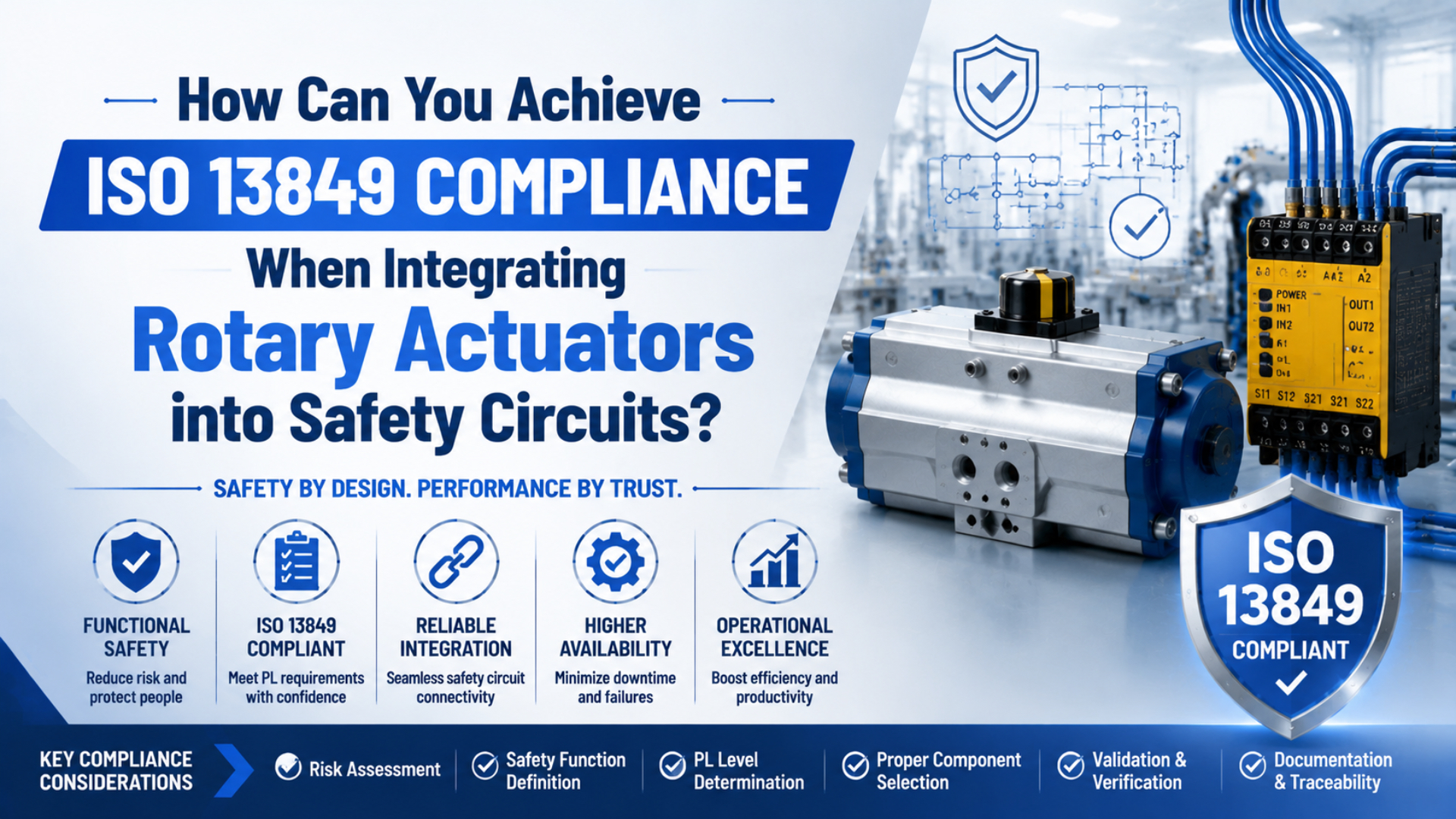
You achieve ISO 13849 compliance by defining a machine safety function, determining its required Performance Level (PLr), designing and evaluating the complete input-logic-output chain, and validating the installed machine response. A rotary actuator does not become “ISO 13849 compliant” by itself. Its valve, feedback, mechanical load, and failure behavior must support the specified safe state.
That distinction matters. A circuit can calculate to the required PL yet still leave a rotary table coasting, dropping an eccentric load, trapping hazardous pressure, or restarting when air returns. The calculation and the physical response have to agree.
Key Takeaways
- ISO 13849-1 defines five Performance Levels, but it does not assign a PLr to a particular rotary actuator application.
- Define stopping angle, holding behavior, pressure state, and restart conditions before selecting valves or sensors.
- Validate the installed axis under credible faults. A SISTEMA result alone is not machine validation.
What Does ISO 13849 Compliance Mean for a Rotary Actuator?
ISO 13849-1:2023 applies to safety-related control systems using electrical, hydraulic, pneumatic, mechanical, and software technologies. It supplies a design and evaluation method, but it does not prescribe a safety function or PLr for a particular application. Compliance therefore belongs to the defined machine safety function, not to a generic actuator label.
The safety function might prevent unexpected rotation when a guard opens. It might stop an indexing table within a measured angle, hold an eccentric load, or inhibit restart until a deliberate reset. Each function needs its own trigger, safe state, PLr, architecture, calculation, and validation evidence.
PLr is the required Performance Level assigned to one safety function. PL is the level achieved by the implemented design and demonstrated through evaluation and validation. They are not interchangeable labels.
Do not mix PL and SIL terminology. ISO 13849 uses Performance Levels from a through e. Standards such as IEC 62061 use Safety Integrity Levels. A product may publish data for more than one framework, but “PLe actuator” is not a substitute for evaluating the complete ISO 13849 safety function.
For a broader explanation of PLr, Category, MTTF_D, DCavg, and CCF, use the ISO 13849 pneumatic safety circuit guide. This article concentrates on the rotary output stage and its machine response.
The most useful compliance question is not “Which actuator has the highest rating?” It is: Which failure can still create hazardous rotation after the control system has demanded the safe state? That question determines whether the actuator, transmission, holding device, sensors, and load behavior must enter the safety analysis.
How Should You Define the Safety Function and Safe State?
ISO 12100:2010 provides the machinery risk-assessment framework that comes before control-system design. ISO 14118:2017 also covers unexpected start-up from pneumatic energy, stored energy such as gravity or springs, and external influences. Start with the hazard and measurable response, not a preferred valve circuit.
Write one specification for each safety function. “Stop the rotary actuator safely” is too vague to validate. A useful specification identifies the following:
| Requirement | Rotary-axis example |
|---|---|
| Trigger | Guard interlock opens during automatic indexing |
| Hazard | Tooling can strike or trap a person within the swept area |
| Required response | Remove driving torque and stop rotation |
| Safe-state limit | No more than the validated angular travel after the demand |
| Holding condition | Shaft remains within the allowed position band under worst-case load |
| Pressure condition | Defined chambers exhaust, remain pressurized, or are isolated as required by the risk assessment |
| Reset behavior | Closing the guard or restoring air cannot initiate rotation |
| Operating modes | Automatic, setup, cleaning, fault recovery, and maintenance are evaluated separately |
| PLr | Assigned to this safety function by risk assessment or an applicable type-C standard |
The safe state is application-specific. Exhausting both actuator ports might remove torque on a horizontal indexer, but the same action can release an eccentric or gravity-loaded arm. A spring-return unit can also move when air is removed. In those cases, controlled blocking, braking, mechanical restraint, or a monitored return path may be needed.
Account for the complete motion profile. The rotary actuator torque guide helps estimate load torque and inertia for sizing, but a torque estimate does not establish the stopping angle or achieved PL. Those require measured machine behavior and safety-control evidence.
Where Does the Rotary Actuator Sit Inside the Safety Function?
IFA guidance explains that an SRP/CS commonly runs from the sensing input through logic to the power-control element, such as a valve. The actuator may sit outside that boundary when its failure cannot create a dangerous state. If actuator or load failure can cause hazardous movement, the relevant actuator and mechanical measures must be included in the safety analysis.
Map the safety function from the hazard backward. Do not stop the diagram at the safety PLC output.
| Layer | Typical rotary-axis elements | Evidence needed |
|---|---|---|
| Input | Guard switch, light curtain, enabling device, position or pressure feedback | Safety data, wiring, mounting, fault response |
| Logic | Safety relay, configurable controller, safety PLC, application software | PL capability, software verification, reset logic, discrepancy times |
| Pneumatic power control | Monitored directional valves, isolation or exhaust elements, pilot circuits | Safety manual, B10D or PFH data, feedback timing, flow limits |
| Actuator and transmission | Vane or rack-and-pinion actuator, shaft, coupling, bearings, brake, stop | Failure modes, mechanical strength, backlash, holding and stop behavior |
| Machine process | Tooling, fixture, eccentric load, swept area, hard stops | Worst-case inertia, gravity torque, impact energy, allowable travel |
A sensor can make the model look complete while observing the wrong point. A valve-position switch confirms a valve element, not shaft position. A shaft sensor mounted before a slipping coupling cannot prove that the tooling stopped. Place diagnostics where they can detect the dangerous failure claimed in the DCavg justification.
The actuator type affects the failure analysis. A vane unit, a rack-and-pinion actuator, and a pneumatic rotary table can differ in leakage paths, backlash, bearing arrangements, stops, and allowable load. Review those differences before substituting one design for another. The rack-and-pinion versus vane guide provides the mechanical comparison; the safety assessment still needs part-specific data.
Which Rotary-Actuator Failures Must the Circuit Address?
ISO 4414:2010 covers significant hazards associated with pneumatic systems used on machinery and remains current after its 2021 confirmation. For a rotary axis, the analysis must connect each credible pneumatic, electrical, sensing, and mechanical failure to the resulting angle, torque, pressure, and restart behavior at the hazard.
Use a failure table during design and validation. The entries below are prompts, not universal fault exclusions or automatic diagnostic credits.
| Credible failure | Possible dangerous effect | Design or diagnostic question | Validation evidence |
|---|---|---|---|
| One valve element fails to shift | Driving pressure remains available | Can one fault defeat the safe state? Is the valve state monitored? | Fault insertion plus pressure and motion trace |
| Exhaust path is restricted | Axis stops later than expected | Are silencers, tubing, and flow controls included in the worst case? | Stop-angle test with permitted restrictions |
| Internal actuator leakage increases | Shaft creeps or loses holding torque | Is leakage detectable before the allowed position is exceeded? | Hold test at pressure and temperature limits |
| Position feedback sticks or disagrees | Controller accepts a false stopped position | What dangerous failures does each sensor detect? | Open, short, stuck, and discrepancy tests |
| Coupling, key, or stop fails | Tooling moves independently of the sensed shaft | Is feedback located on the hazard side of the failure? | Mechanical inspection and justified fault treatment |
| Supply air is lost or restored | Load drops, spring return moves, or cycle restarts | What state occurs at zero pressure and during repressurization? | Air interruption and restoration tests |
| Hose ruptures or a port opens | Uncontrolled rotation or loss of holding | Is an independent brake or restraint required? | Credible line-failure analysis and physical test where safe |
| Shared contamination affects both channels | Redundant valves fail by a common cause | Are air quality, filtration, maintenance, and channel separation controlled? | CCF review and maintenance evidence |
| Reset logic is incorrect | Reset initiates motion | Is reset separate from the start command? | Mode-by-mode reset and restart tests |
Redundancy alone does not remove common-cause failure. Two identical valves can share contaminated air, excessive pressure, incorrect maintenance, a blocked common exhaust, or the same software error. The CCF assessment must record the measures actually implemented.
Likewise, spring return is a behavior, not a safety verdict. Determine the return direction, available spring torque across the stroke, load torque, speed, pinch points, end-stop energy, and what happens if the spring or mechanical connection fails.
How Do PLr, Category, MTTF_D, DCavg, and PFH Fit Together?
The 2025 IFA report for ISO 13849-1:2023 lists five PL bands, each tied to a range of the mean frequency of a dangerous failure per hour, PFH. The achieved PL also depends on architecture, component reliability, diagnostic coverage, common-cause measures, systematic controls, and correct integration. Category alone cannot establish PL.
| Performance Level | PFH range per hour |
|---|---|
| PL a | >= 10^-5 to < 10^-4 |
| PL b | >= 3 x 10^-6 to < 10^-5 |
| PL c | >= 10^-6 to < 3 x 10^-6 |
| PL d | >= 10^-7 to < 10^-6 |
| PL e | >= 10^-8 to < 10^-7 |
Some existing manuals and tools use the older notation PFH_D; current 2023-edition IFA material uses PFH. Follow the terminology and calculation method of the standard revision used for the project, and keep the selected revision consistent across reports and libraries.
PFH is the mean frequency of a dangerous failure per hour used in the current IFA material for ISO 13849-1:2023. It is one part of the PL result, not a complete statement that the physical machine response is safe.
For wear-dependent pneumatic components, request the exact manufacturer’s B10D, PFH, or subsystem data and its conditions of use. Do not assign a generic 20-million-cycle value to an actuator or valve. Switching rate, pressure, air quality, temperature, load, maintenance, mission time, and approved accessories can change whether the data apply.
The IFA SISTEMA tool evaluates designated architectures using PLr, Category, MTTF_D, DCavg, and CCF. IFA maps SISTEMA 3.x to ISO 13849-1:2023; Version 2.x belongs to the 2015 revision. Do not mix projects, libraries, and assumptions from different revisions without review.
In SISTEMA, create a separate safety function for each hazardous response. Model the real input, logic, and output subsystems, then document any actuator or mechanical measures that sit outside the quantitative model but remain necessary for the safe state. A green calculation cannot detect a slipping coupling, blocked silencer, wrong sensor location, or unstable load.
How Should You Validate the Installed Rotary-Axis Safety Function?
ISO 13849-2:2012 remains the current published validation standard as of July 17, 2026. It requires validation by analysis and testing of the specified safety functions, achieved Category, and achieved PL. ISO lists a replacement draft, but a draft is not the published validation basis.
Set measurable acceptance criteria before commissioning. Record the maximum allowed angle after the safety demand, stopping time, shaft position band, pressure threshold, holding duration, reset behavior, and fault reaction. Test at the combinations most likely to produce the worst response:
- Maximum permitted moving mass and radius
- Highest credible angular speed
- Worst gravity or eccentric-load orientation
- Minimum and maximum supply pressure
- Lowest permitted temperature if seals and valve timing are affected
- Longest approved tubing and most restrictive permitted exhaust arrangement
- Worn but serviceable mechanical clearances
- Every operating mode in which a person can approach the hazard
Measure more than the controller status bit. Time-correlate the safety demand, logic output, valve feedback, downstream pressure, shaft angle, and hazardous tooling position. A catalogue valve switching time is not the machine stopping time.
For rotary equipment, stopping angle is often more useful than stopping time alone. The same 150 ms stop can be acceptable at one angular speed and hazardous at another. Record both values, then compare the swept path with the guard distance and the safety-function acceptance criteria.
Fault testing should match the architecture and failure analysis. Where safely practicable, prevent one valve element from changing state, create feedback discrepancies, interrupt one input channel, restrict an exhaust within the allowed configuration, remove and restore air, and test reset behavior. Confirm that the next hazardous cycle is inhibited when the specification requires it.
Inspection and functional-test intervals must come from the risk assessment, component safety manuals, Category and diagnostic design, operating environment, usage, maintenance history, and any applicable type-C standard. ISO 13849 does not impose a generic schedule such as “monthly for PL e” or “annually for PL c.”
What Documentation Makes the Design Audit-Ready?
IFA’s current SISTEMA page states that Version 3.x is assigned specifically to ISO 13849-1:2023 and can print a summary of the evaluated safety function. That report is one record, not the complete compliance file. The file must also connect the risk assessment, circuit, software, component data, machine tests, and controlled revisions.
Keep these records under configuration control:
- Machine limits, hazard analysis, and risk-reduction decisions
- Safety-function specification and PLr rationale for each function
- Pneumatic and electrical schematics with exact component revisions
- Software version, checksum, parameter set, and verification records
- Manufacturer safety manuals, B10D or PFH data, and SISTEMA libraries
- Category, MTTF_D, DCavg, CCF, PFH, and systematic-measure evidence
- Failure analysis for valves, sensors, actuator, coupling, stops, brake, and load
- Validation plan, measuring equipment, raw traces, results, and deviations
- Inspection, maintenance, replacement, and functional-test requirements
- Change-control record for substitutions, tubing, silencers, pressure, load, speed, and software
Supplier documentation should name the exact part and revision covered. Ask for declared safety functions, architecture restrictions, diagnostic timing, permitted test pulses, mission time, switching frequency, pressure and air-quality limits, approved silencers, maintenance conditions, and any certificate or declaration actually applicable to that component.
Do not request an “ISO 13849 rotary actuator” without context. Give the supplier the safety function, PLr, pressure range, cycle count, load, orientation, stopping requirement, feedback concept, environment, and proposed valve arrangement. That information allows the component data to be checked against the real application.
FAQs About ISO 13849 Rotary Actuator Integration
ISO 13849-1:2023 is a 152-page methodology for safety-related control systems, while the current ISO 13849-2 validation document contains 79 pages. These common questions clarify the boundaries that short product descriptions usually omit: component capability, architecture, diagnostics, safe-state behavior, testing, and machine-level validation.
Can a rotary actuator itself be certified as PL e?
A supplier can provide safety data, a declared subsystem capability, or third-party certification for a defined product and use conditions. That does not make the complete machine safety function PL e. ISO 13849-1 states that it does not specify product-level design requirements for every component; the integrator must evaluate and validate the complete function.
Is Category 3 automatically equal to PL d?
No. Category 3 describes architectural fault behavior, not the complete achieved PL. The result also depends on MTTF_D, DCavg, CCF, systematic measures, software, subsystem interfaces, and the calculated PFH. IFA’s Performance Level guidance combines deterministic architecture with those probabilistic and diagnostic properties.
Does a spring-return actuator guarantee a safe state?
No. ISO 14118:2017 treats pneumatic supply, gravity, compressed springs, and external influences as possible sources of unexpected start-up or movement. A spring return is safe only if its direction, torque, speed, stopping energy, load interaction, and credible failures satisfy the safety-function specification.
Is dual position feedback enough to claim diagnostic coverage?
No. Diagnostic coverage depends on which dangerous failures the diagnostics detect and when they detect them. Two sensors can share a mounting error, observe the same side of a failed coupling, or miss a valve fault. Map each credited diagnostic to a failure mode and verify its fault reaction.
How often must the rotary safety function be tested?
There is no universal interval based only on PL. Set the interval using the component instructions, operating frequency, Category and diagnostic architecture, environment, maintenance history, risk assessment, and applicable machine-specific standards. Category 2 testing requirements also concern the relationship between test and demand behavior, not a generic monthly calendar.
Should the actuator be modeled in SISTEMA?
It depends on the safety-function boundary and dangerous failure behavior. IFA guidance notes that the power-control element often ends the SRP/CS, but actuator properties must be considered when actuator or load failure can create a hazardous state. Document both the quantitative model and any necessary mechanical measures outside it.
Conclusion
ISO 13849-1:2023 provides a five-level method for designing safety-related control systems, not a compliance label for a stand-alone rotary actuator. A defensible integration starts with one measurable safety function, evaluates the complete control chain, addresses physical rotary-axis failures, and validates the installed machine against its acceptance criteria.
Define what must happen when the guard opens, a sensor fails, a valve sticks, air disappears, or pressure returns. Then prove the axis reaches and maintains the specified safe state under the worst credible load and motion conditions. That evidence, not a component nameplate or a SISTEMA screenshot, is the foundation of compliance.
Sources and Retrieval Dates
The technical claims above use current ISO catalogue records and DGUV/IFA implementation guidance. Retrieval dates are included because ISO 13849-2 is under revision and SISTEMA versions are tied to specific editions of ISO 13849-1. Project teams should confirm the published standard and software revision again when the machine is validated.
- International Organization for Standardization. ISO 13849-1:2023 - Safety-related parts of control systems, Part 1. Published April 2023. Retrieved July 17, 2026.
- International Organization for Standardization. ISO 13849-2:2012 - Validation. Current published edition; draft replacement under development. Retrieved July 17, 2026.
- International Organization for Standardization. ISO 12100:2010 - Risk assessment and risk reduction. Retrieved July 17, 2026.
- International Organization for Standardization. ISO 14118:2017 - Prevention of unexpected start-up. Confirmed current in 2023. Retrieved July 17, 2026.
- International Organization for Standardization. ISO 4414:2010 - Pneumatic fluid power safety requirements. Confirmed current in 2021. Retrieved July 17, 2026.
- Institute for Occupational Safety and Health of the German Social Accident Insurance. IFA Report 1/2025 - Functional safety of machine controls. Retrieved July 17, 2026.
- Institute for Occupational Safety and Health of the German Social Accident Insurance. SISTEMA software for ISO 13849-1. Retrieved July 17, 2026.
- Institute for Occupational Safety and Health of the German Social Accident Insurance. Hydraulic and pneumatic machine-safety resources. Retrieved July 17, 2026.