

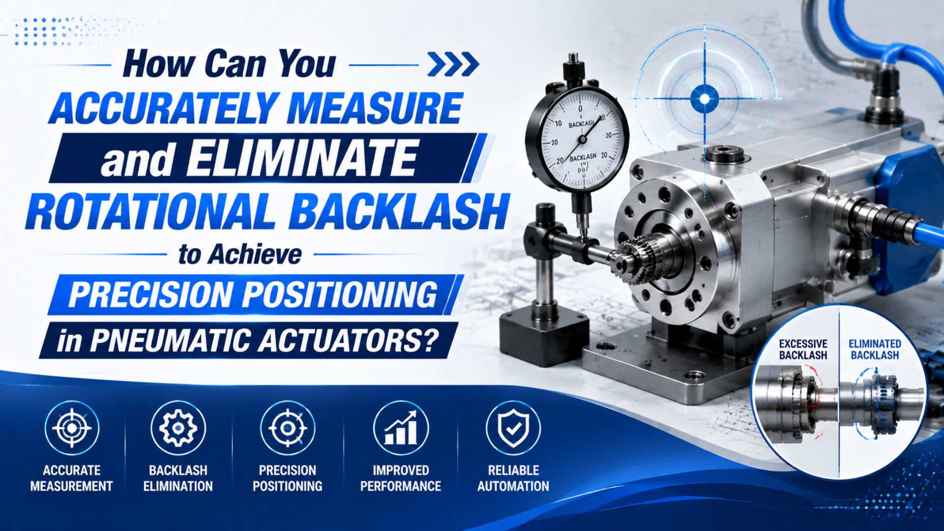
Measure rotational backlash at the driven output, approach the same target from both directions, and apply a defined reversal torque under controlled pressure and load. The angular difference between the two seated positions is the system’s directional lost motion. You can often reduce it, but you should not promise zero backlash until the complete actuator, shaft connection, fixture, and load have passed a bidirectional acceptance test.
That distinction matters because a catalog value for an actuator does not include every source of movement in the installed machine. A loose key, compliant bracket, worn bearing, internal stop, changing air pressure, and a sensor mounted upstream of the load can all make the final tool position shift when direction reverses. In our experience reviewing pneumatic applications, the installed output result therefore controls the decision; an internal actuator value is only one part of the error budget.
Key Takeaways
- Define whether you need shaft backlash, end-stop repeatability, or loaded system reversal error before testing.
- Measure at the output or process datum with the same pressure, load, direction, and torque used in acceptance testing.
- Convert tangential indicator movement to angle with the actual indicator radius.
- Separate clearance from elastic deflection before choosing a mechanical or control remedy.
- Verify the repair from both directions; software cannot compensate for loose or changing mechanics.
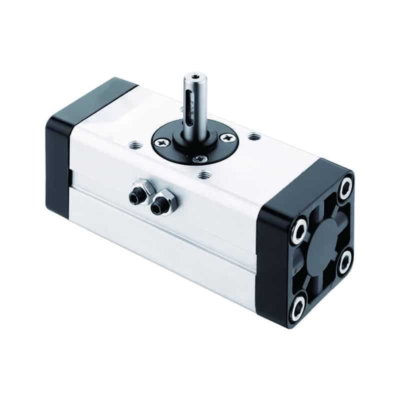
If you first need to compare vane, single-rack, and double-rack mechanisms, read the pneumatic rotary actuator operating guide. This article starts with an actuator already installed or selected and focuses on measurement and correction.
What Does Rotational Backlash Actually Mean?
Rotational backlash is the angular lost motion observed after the input reverses but before the output becomes positively loaded in the opposite direction. In a rack-and-pinion actuator, gear-tooth clearance is one source. The installed machine can add clearance at the key, spline, coupling, bearing, mounting face, index plate, or workholding fixture.
Do not use backlash as a catch-all term for every position error:
| Term | What it describes | How to recognize it |
|---|---|---|
| Backlash or lost motion | Output change needed to take up clearance after reversal | Direction-dependent gap around reversal |
| Elastic compliance | Deflection that increases with applied torque | Position changes progressively as torque rises |
| Repeatability | Spread when the same target is approached repeatedly under the same conditions | Variation among repeated runs from one direction |
| Accuracy | Difference between measured output position and the commanded or nominal position | Consistent offset from the target |
| Resolution | Smallest increment a sensor or controller can report | A digital step size, not proof of load position |
| End-stop stability | Ability to seat at the same mechanical stop under pressure | Depends on stop stiffness, impact, pressure, and load |
This terminology prevents a common diagnostic mistake. If the position changes smoothly as reversal torque increases, the problem is not only a gap between teeth; shaft twist, bracket bending, bearing deflection, or load movement may dominate. If the encoder repeats but the tool does not, the sensor may be upstream of the loose interface. The feedback-sensor integration guide explains why sensor resolution and machine accuracy are different specifications.
Product architecture also changes the result. SMC states that its CRA1 single-rack series can have output-shaft backlash at the swing end and recommends an external stopper where required. For its CRQ and MSQ double-piston designs, one piston can continue loading the pinion after the other reaches the stop, absorbing end-position backlash; SMC also notes that holding torque at that condition is half the effective torque (SMC rotary actuator FAQ, accessed July 17, 2026). That is a model-specific end-position behavior, not a universal claim that every double-rack actuator is backlash-free throughout its travel.
Define the Measurement Before Touching the Actuator
A useful result needs a written measurand: the exact quantity the test is intended to determine. Choose one of these before building the fixture:
- Unpressurized shaft play: a service check for mechanical clearance after stored energy has been safely removed.
- Pressurized end-position movement: the output movement around an internal or external stop under specified pressure and torque.
- Installed system reversal error: the change at the process datum when the machine approaches the same target clockwise and counterclockwise.
- Bidirectional positioning performance: repeated position measurements at several targets across the working angle.
The third measurement is usually the most valuable for assembly and inspection equipment because it includes the interfaces that affect the part. The first is useful for isolating wear, but it cannot predict loaded process accuracy by itself.
Record the test conditions with the result:
| Test condition | What to document |
|---|---|
| Target position | End stop, intermediate angle, or several positions across travel |
| Pressure | Actual actuator-inlet pressure during seating or movement |
| Load | Attached mass, center of gravity, external torque, and fixture state |
| Reversal torque | Magnitude, direction, application point, and dwell time |
| Speed | Approach speed and flow-control setting |
| Temperature | Machine and ambient condition after warm-up |
| Measurement chain | Sensor type, resolution, mounting radius, and calibration status |
| Repetitions | Number of clockwise and counterclockwise approaches |
ISO 230-2 uses repeated direct measurements at each position to evaluate positioning accuracy and repeatability for both linear and rotary numerically controlled axes. A pneumatic indexer is not automatically an ISO 230-2 machine axis, but the same discipline of defined positions, repeated measurements, both approach directions, and stated uncertainty is a sound basis for an acceptance method (ISO 230-2:2014, accessed July 17, 2026).
Do not apply hand torque to a live production mechanism. Perform pressurized tests only in a guarded test mode with an approved procedure. For mechanical isolation, exhaust stored pneumatic energy, prevent restart, support gravity loads, and follow the machine’s lockout and risk-control requirements.
How Do You Measure Backlash With a Dial Indicator?
A dial indicator provides a practical field measurement when the expected tangential movement is large enough for the indicator and fixture to resolve. Mount a rigid test arm to the output, place the indicator tip tangent to the arm at a measured radius, and use a torque wrench or calibrated force at a known lever arm to apply equal reversal torque.
Use this sequence:
- Mark the output, actuator body, test-arm radius, and positive direction.
- Bring the axis to the target from clockwise rotation at the specified slow approach speed.
- Apply the defined clockwise seating torque and record the indicator reading after the dwell time.
- Reverse through the same target, apply the same magnitude of counterclockwise torque, and record the second reading.
- Repeat the pair several times without moving the fixture or indicator.
- Run the same test at other working angles if the application uses intermediate positions.
- Report the mean directional difference and the spread, not only the smallest result.
For a tangential displacement d measured at radius r:
Angular lost motion in radians = atan(d / r)
For small angles: angle in radians is approximately d / r
Angle in degrees = atan(d / r) x 180 / pi
Angle in arcminutes = angle in degrees x 60
Suppose the indicator moves 0.26 mm between equal clockwise and counterclockwise seating torques at a 100 mm radius:
angle = atan(0.26 / 100) x 180 / pi
angle = 0.149 degrees, or about 8.9 arcminutes
Call this result system lost motion at the stated reversal torque, unless a separate isolation test proves that it comes only from the actuator gearing. The fixture, output shaft, coupling, and test arm are all inside the measurement loop.
Indicator resolution must be selected from the allowed angular error and the available radius. At a 100 mm radius, 0.02 degrees produces only about 0.035 mm of tangential movement. A loose magnetic base or flexible arm can therefore consume the entire measurement budget. Increase the radius when space and stiffness allow, use a rigid stand, and check the fixture by applying torque without crossing the suspected clearance zone.
When Should You Use an Output Encoder or Laser System?
Use an output-side encoder when you need continuous angle data, measurements at many positions, or correlation with valve commands and pressure. Mounting the encoder on the actuator input or controller motor does not capture lost motion downstream of that sensor. Record clockwise and counterclockwise approaches separately, then compare the measured load angle at identical commands and conditions.
Encoder resolution is the smallest angular increment the device can report; it is not the installed axis accuracy. Check encoder accuracy, mounting eccentricity, coupling stiffness, interpolation error, data-acquisition timing, and the alignment between the encoder datum and process datum. NIST researchers have shown in precision angle metrology that installing an encoder can change its performance from the manufacturer’s calibration data, which is why an in-situ output check remains important (NIST angle-stage characterization, accessed July 17, 2026). For a closed-loop pneumatic axis, also verify that the proportional valve and controller can correct the measured error; see the servo pneumatic positioning guide for that control boundary.
A laser rotary-axis calibration system is justified when the tolerance and required traceability exceed a shop-floor indicator or installed encoder. Renishaw’s XR20 works with its XL-80 or XM-60 laser system and uses a high-accuracy encoder and angular retroreflector to calibrate rotary axes. The manufacturer specifies system verification to ±1 arcsecond, but that is the capability of the calibration system under its defined setup, not the accuracy a pneumatic actuator will achieve after calibration (Renishaw XR20, accessed July 17, 2026).
How Do You Separate Clearance From Compliance?
Plot output angle against applied torque through a slow clockwise-to-counterclockwise reversal. A near-horizontal region in which torque changes but the output has not positively engaged the opposite flank indicates clearance or lost motion. The sloped regions after engagement show torsional compliance. Slip appears as an abrupt, non-repeatable position change; stiction can create a breakaway jump that resembles clearance unless the test is repeated at several torque levels.
Then shorten the mechanical chain one interface at a time:
| Isolation test | If the measured movement drops | Likely contributor |
|---|---|---|
| Measure actuator shaft instead of load plate | Error disappears downstream | Coupling, key, bracket, fixture, or load bearing |
| Remove the coupling and inspect shaft play safely | Error remains at actuator output | Internal gear, bearing, shaft, or stop mechanism |
| Repeat at two reversal torques | Error grows mainly with torque | Compliance, clamp slip, shaft twist, or bearing deflection |
| Repeat at two controlled pressures | End position changes with pressure | Stop seating, pneumatic preload, seal friction, or load balance |
| Compare several angular positions | Error is localized | Gear-tooth wear, damaged sector, or position-dependent fixture load |
| Approach the same target from one direction only | Spread improves but bidirectional error remains | Backlash is being masked, not removed |
Inspect simple interfaces before replacing the actuator. Check key and keyway fit, split-clamp torque, spline engagement, fastener preload, bracket flatness, shaft alignment, bearing support, external stops, and whether the load exceeds published radial or axial shaft limits. A coupling that accommodates misalignment is not automatically zero-backlash; its joints or elastomer can introduce clearance or torsional wind-up.
Match the Fix to the Measured Root Cause
The best remedy removes the measured mechanism without creating a larger torque, wear, or safety problem.
Repair the output connection and support the load
Replace damaged keys, hubs, pins, or splines; correct clamp and fastener preload; align the shaft; and add an external bearing when the actuator output should not carry the machine’s overhung load. Recheck the manufacturer’s allowable radial load, axial load, and moment. Tightening a worn connection beyond its rated torque is not a repair.
Use a positive stop or clamp for critical end positions
When the process needs precision only at one or two endpoints, a rigid external stop can establish the process datum outside the gear clearance. Apply the stop load through a structure designed to carry it, control impact energy, and confirm that the actuator maintains the required seating torque. A clamp or mechanical lock may be more appropriate when the position must resist an external disturbance or remain safe after air loss.
The SMC CRA1 operating manual illustrates why model detail matters: most listed CRA1 sizes specify backlash within 1 degree, while size 30 is identified as having no backlash under pressure because a stopper is installed (SMC CRA1 operation manual, accessed July 17, 2026). Use the exact model manual and test condition rather than transferring that exception to other sizes.
Select an anti-backlash or preloaded architecture
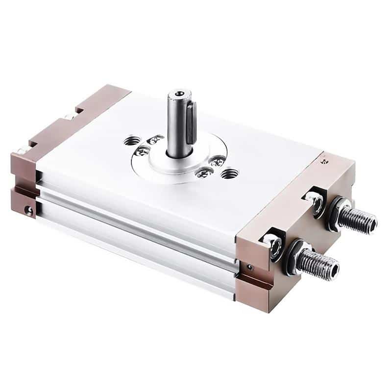
Preloading keeps mating surfaces engaged so direction reversal does not first have to cross an unloaded clearance. Implementations include opposing racks, spring-loaded rack shoes, split gears, preloaded bearings, and model-specific double-piston arrangements. Parker’s XR anti-backlash option, for example, uses a spring and shoe to press the rack and pinion together; the same catalog states that the option raises breakaway pressure by an amount that varies with actuator size (Parker XR Series catalog, accessed July 17, 2026).
Preload is therefore a trade, not a free correction. It can increase friction, starting pressure, heat, and wear or reduce usable holding torque. Recalculate torque at the minimum moving pressure and repeat the rotary actuator sizing checks after changing the preload arrangement or actuator type.
Use one-direction final approach only when the process permits it
Approaching every target from the same direction keeps the same tooth flanks and interfaces loaded. This can improve a unidirectional indexing sequence, but it adds travel and cycle time and does not protect against external torque that reverses the load after seating. Document it as a motion strategy, not as proof that backlash has been eliminated.
Apply electronic compensation only to stable residual error
A controller can add a direction-dependent offset or use output feedback to correct repeatable reversal error. Build the compensation map at representative positions, loads, pressures, speeds, and temperatures, then validate it with an independent output measurement. Do not compensate a loose coupling, intermittent slip, progressive wear, or pressure-dependent stop because the error will not remain equal to the stored correction.
If the application needs precise intermediate positioning during frequent reversals, high stiffness under changing torque, or reliable holding without air, a servo-pneumatic system may still be the wrong architecture. Compare a purpose-built precision rotary table or electric direct-drive/servo solution against the complete pneumatic system rather than adding layers of compensation to unstable mechanics.
How Do You Set a Defensible Acceptance Limit?
Start at the process feature, not at a generic actuator tolerance. Convert the allowed tangential error at the tool radius into an angular budget, then allocate part of that budget to the actuator and the rest to the coupling, fixture, bearings, sensor, thermal change, and measurement uncertainty.
Allowable system angle = atan(allowable tangential error / process radius)For example, a tool allowed to move 0.20 mm at a 300 mm radius has a total angular allowance of approximately 0.038 degrees. The actuator cannot consume all of it if the bracket, fixture, sensing, and measurement chain also contribute error. Use the machine drawing, process capability requirement, or validated risk analysis to set the allocation; do not import a tolerance from an unrelated industry table.
An acceptance record should include:
- actuator model and serial or asset number
- shaft, key, coupling, stop, and mounting configuration
- minimum inlet pressure during the test
- load, orientation, approach speed, and reversal torque
- measurement radius, instrument, calibration status, and resolution
- clockwise and counterclockwise results at each target
- mean directional difference, repeated-run spread, and uncertainty statement
- pass/fail limit and the document that owns that limit
Keep the fixture and procedure stable for maintenance trending. A rising value then supports inspection, but do not assign a universal annual wear rate. Cycle count, lubrication, shock loading, contamination, shaft load, material, and maintenance quality can change the progression.
FAQs About Rotational Backlash in Pneumatic Actuators
Can a pneumatic rotary actuator have zero backlash?
Some manufacturers describe a particular model or end-position mechanism as no-backlash or anti-backlash under stated conditions. That does not prove zero movement at the installed tool. Verify the complete load path from both directions at the required pressure, load, torque, and temperature, and report the instrument uncertainty with the result.
Is repeatability the same as backlash?
No. Repeatability is the spread among repeated approaches made under the same conditions. Backlash is direction-dependent lost motion after reversal. An axis can repeat well when every target is approached clockwise yet show a large position difference when the same target is approached counterclockwise.
Where should I mount an encoder for backlash compensation?
Mount the measurement as close as practical to the controlled process datum. An encoder upstream of a loose key, flexible coupling, or compliant fixture cannot observe that downstream movement. If the controller uses an internal sensor, validate the final load position with an independent output-side instrument.
Can pneumatic preload remove gear backlash?
Preload can keep gear flanks engaged and greatly reduce reversal clearance, but the result depends on the actuator architecture and operating point. It can also increase friction or breakaway pressure and may change usable holding torque. Recheck torque, pressure, speed, wear, and acceptance results after applying it.
How often should rotational backlash be measured?
Set the interval from machine risk, cycle count, impact loading, process capability, and observed trend. Measure again after actuator, coupling, bearing, stop, pressure, or fixture work and whenever bidirectional position results drift. A universal yearly increase or fixed calendar interval is not technically defensible.
Rotational backlash is controlled by evidence, not by a single catalog adjective. Define the process datum, measure both directions under a stated reversal torque, isolate each mechanical interface, correct the mechanism that actually moves, and repeat the same acceptance test. If the application drawing, load data, or actuator specification does not provide enough information to set that test, send the details through the technical contact page before approving a replacement or compensation strategy.