

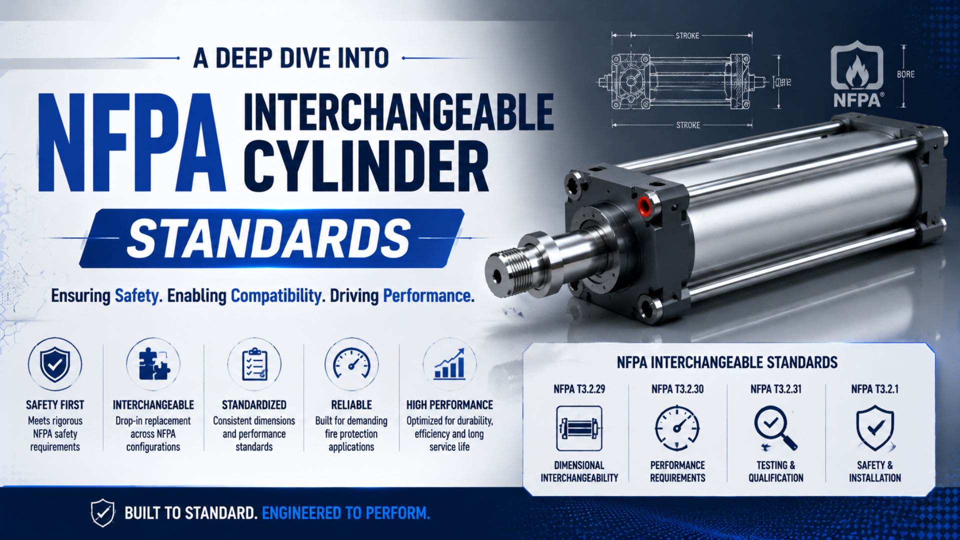
NFPA interchangeable cylinder standards create common mechanical interfaces for cataloged square-head industrial cylinders. They do not make every cylinder with the same bore and mounting code identical. The governing dimensional standard, supplier configuration, and machine acceptance criteria answer three different questions.
In this article, NFPA means the National Fluid Power Association, not the National Fire Protection Association. The primary reference is NFPA/T3.6.7 R3-2009 (R2024), which establishes mounting dimensions for dimensionally interchangeable square-head industrial fluid-power cylinders. It covers pneumatic cylinders as well as specified hydraulic categories.
Key Takeaways
- NFPA/T3.6.7 standardizes mounting dimensions, not complete functional performance.
- MS2, MF1, MP1, and MT1 are mounting-style codes, not separate cylinder standards.
- Match the exact standard revision, bore, stroke, mounting, rod end, ports, options, and installed length.
- Release a substitute only after drawing review, first-article inspection, and machine testing.
Which NFPA Standard Controls Interchangeable Square-Head Cylinders?
The current ANSI listing is NFPA/T3.6.7 R3-2009 (R2024), and its scope names 3 cylinder categories: heavy-duty hydraulic, light-duty hydraulic, and pneumatic square-head industrial cylinders (ANSI Webstore). The document establishes mounting dimensions needed for dimensional interchangeability, not a complete product specification.
The title matters: Fluid power systems and products - Square head industrial cylinders - Mounting dimensions. This is not a universal standard for every pneumatic cylinder shape. Round-body cylinders, compact cylinders, rodless cylinders, guided actuators, and metric ISO families follow different dimensional systems or supplier-controlled interfaces.
The public preview explains that the square-head design was developed for industrial use and is sold by many suppliers as a dimensionally interchangeable component. It also states that manufacturers retain freedom of internal design while following the mounting guidelines required for interchangeability (NFPA/T3.6.7 preview).
Two related documents help define the broader family:
- NFPA/T3.6.8 R3-2010 covers nominal dimensions for accessories used with cataloged square-head industrial cylinders. Its scope says those dimensions support interchangeability and do not prove suitability for a particular service (ANSI listing).
- NFPA/T3.6.11 R1-1998 (R2024) addresses recommended bore and rod combinations, rod-end configurations, and mounting dimensions for cataloged square-head tie-rod cylinders below 1.5 in bore (ANSI listing).
Always name the exact document and revision in a drawing, specification, or RFQ. The phrase “NFPA cylinder” is a family description, not a complete technical requirement.
What Does Dimensional Interchangeability Actually Promise?
NFPA/T3.6.7 states 2 purposes: establish uniform mounting dimensions and allow manufacturers freedom of cylinder design while preserving the basic guidelines needed for dimensional interchangeability (standard preview). Those purposes define the promise and deliberately separate common interfaces from supplier-specific engineering choices.
Dimensional interchangeability means the specified mounting interfaces can occupy the same mechanical location when the bore, mounting style, stroke-related dimensions, and other controlled features match. It does not mean the internal construction, seal package, cushioning, friction, leakage, speed capability, temperature range, or expected life is identical.
The distinction is easier to manage with three evidence layers:
| Evidence layer | What it controls | What it cannot prove alone |
|---|---|---|
| NFPA dimensional standard | named mounting dimensions and identification conventions | supplier options, pressure rating, speed, environment, life |
| Configured supplier drawing and catalog | exact envelope, rod end, ports, options, and product ratings | performance on the installed machine |
| Machine acceptance specification | force, timing, sensing, cushioning, environment, and safety behavior | continued supply of the same revision unless change control is added |
An effective replacement record assigns every requirement to one of those owners. If a dimension comes from NFPA/T3.6.7, cite the standard. If it comes from a catalog option, cite the configured drawing. If it comes from the machine, give it a measurable acceptance limit. This prevents an NFPA label from being used as evidence for a feature the standard never controls.
The standard does not remove engineering work. It removes uncertainty from a defined set of interfaces so the remaining configuration and application checks can be completed more efficiently.
NFPA Mounting Style Codes Are Interfaces, Not Separate Standards
Parker’s current Series 2A literature presents 13 standard mounting styles, including NFPA codes MX0, MF1, MS2, MP1, and MT1 (Parker Series 2A catalog). The letters identify mounting geometry, while the supplier’s separate style letters identify its ordering choices; neither defines an independent duty class.
| NFPA code | Mounting interface | Practical replacement check |
|---|---|---|
| MX0 | basic cylinder, no external mount | envelope, tie-rod arrangement, and how the machine adds its own support |
| MX1 | tie rods extended at both ends | tie-rod projection, thread, hole clearance, and installed length |
| MX2 | tie rods extended at cap end | cap-end attachment and service clearance |
| MX3 | tie rods extended at head end | rod-end attachment and service clearance |
| MF1 | head rectangular flange | flange face, bolt pattern, centerline, and pilot or locating features |
| MF2 | cap rectangular flange | flange face, bolt pattern, centerline, and stroke-related length |
| MF5 | head square flange | square flange dimensions and fastener access |
| MF6 | cap square flange | square flange dimensions and machine clearance |
| MS2 | side lug | lug spacing, mounting surface height, and fastener pattern |
| MS4 | side tapped | tapped-hole location, thread, engagement, and base flatness |
| MP1 | cap fixed clevis | clevis width, pin diameter, centerline, and permitted articulation |
| MP5 | cap spherical bearing | bearing width, pin interface, articulation, and load direction |
| MT1, MT2, MT4 | head, cap, or intermediate trunnion | trunnion diameter, location, bearing support, and pivot alignment |
Mounting code alone is not enough. A 4 in bore MS2 cylinder and a 2 in bore MS2 cylinder do not share the same dimensions. The code says which dimensional pattern to compare; bore and configuration select the actual values.
It is also unsafe to infer application quality from the code. MF1 does not mean “medium-duty flange standard,” and MP1 does not assign a universal pressure rating. The supplier’s product series and configured catalog establish those ratings.
Which Dimensions Must Match Before a Cylinder Is Released?
SMC’s NCA1 family spans 1.5 to 8 in bores and offers at least 11 mounting styles, while some single-rod variants list 22 styles (SMC NCA1). The range also contains different rod, stroke, mounting, and environmental options, making the complete configuration more important than the NFPA label alone.
Compare the installed cylinder, incumbent drawing, and proposed supplier drawing at the same bore, stroke, rod arrangement, and mounting code. A transparent CAD overlay is helpful, but it must use controlled drawings rather than generic product images.
At minimum, verify:
- Bore and stroke. Confirm nominal bore, actual ordered stroke, stroke tolerance, and whether stops or spacers change usable travel.
- Mounting interface. Compare every mounting dimension, thread, hole, counterbore, pin, flange, lug, and trunnion feature named by the selected style.
- Cylinder centerline. Check the distance from the machine mounting surface or pivot axis to the piston-rod centerline.
- Retracted and extended envelope. Compare installed length, rod extension, stroke-dependent dimensions, sensor clearance, and removal path.
- Piston rod. Match rod diameter, rod-end style, thread form, gender, usable engagement, wrench flats, shoulder, and jam nut.
- Ports. Match thread designation, size, location, orientation, seal method, fitting clearance, and required flow capacity.
- Adjustment access. Confirm that cushion needles, flow controls, and sensors remain reachable after installation.
- Accessories. Check clevises, eyes, pins, brackets, spherical bearings, and their load ratings as configured components.
Do not copy a universal tolerance table from a reseller article. The applicable limits must come from the purchased NFPA document, the supplier’s controlled drawing, or a justified machine-interface requirement. Record the source beside each critical characteristic.
In our experience, the most frequently missed differences are not the visible flange or lug pattern. They are rod-end engagement, port sealing method, cushion access, sensor position, and the retracted length at the ordered stroke. A drawing overlay catches those differences before a mechanically “close” substitute reaches the machine.
The mounting and alignment guide explains why a dimensionally correct mount still needs proper load alignment and freedom from side loading.
What Does an NFPA Mounting Match Not Guarantee?
SMC lists NCA1 options ranging from smooth motion at 0.4 in/s to high-temperature service at 300°F, even though the products remain within an NFPA interchangeable family (SMC NCA1). These supplier-controlled differences remain application-critical even when the standardized mounting dimensions agree.
The NFPA mounting match does not automatically guarantee:
- working or proof pressure;
- piston speed and breakaway behavior;
- seal friction, leakage, or service life;
- adjustable, fixed, self-adjusting, or absent cushioning;
- permissible cushion energy or external stop requirements;
- magnetic piston, sensor type, switch location, or connector;
- port flow capacity or regional thread option;
- temperature, corrosion, washdown, chemical, or cleanroom suitability;
- rod material, coating, hardness, or buckling capacity;
- side-load capability, guide requirement, or mounting rigidity;
- repair kits, spare-parts continuity, or maintenance procedure.
Two supplier catalogs make the boundary visible. Parker’s Series 2A literature includes several rod-end thread styles and special rod-end dimensions, while SMC’s NCA1 line includes temperature, low-speed, adjustable-stroke, material, and seal options. Neither set of options is defined by the mounting code itself.
Functional equivalence needs calculations and tests. Verify extension and retraction force at the actual dynamic pressure, then check speed, cushioning, leakage, sensing, environment, and duty cycle. The Cylinder Force Calculator provides a first-pass force check; long compression rods also need a separate Rod Buckling Calculator.
Two cylinders can be fit-equivalent and still fail to be machine-equivalent. The first term means the controlled interfaces install correctly. The second means the configured product performs the required motion safely and repeatably. Record both decisions instead of hiding them behind one “approved alternate” checkbox.
NFPA and ISO Cylinder Families Are Not the Same
NFPA/T3.6.7 uses customary U.S. units, while ISO 15552:2018 covers detachable-mount pneumatic cylinders from 32 to 320 mm bore at a maximum rated pressure of 1,000 kPa, or 10 bar (NFPA preview; ISO 15552). Their dimensions, accessories, and catalog conventions must be verified independently.
The NFPA preview explains that metric dimensions were not added because ISO 15552 and related ISO standards provide metric mounting systems for similar products. That makes NFPA and ISO parallel classification routes, not two names for one mounting envelope.
| Question | NFPA square-head inch series | ISO 15552 metric series |
|---|---|---|
| Primary dimensional reference | NFPA/T3.6.7 | ISO 15552 |
| Unit system | customary U.S. units | metric |
| Typical family description | square-head industrial tie-rod cylinder | detachable-mount pneumatic cylinder |
| Mounting identification | NFPA/ISO 6099-style codes used in supplier catalogs | ISO mounting and dimension codes |
| Replacement rule | compare the exact NFPA style and configured drawing | compare the exact ISO family, mount, and configured drawing |
An ISO 15552 cylinder is not a drop-in NFPA replacement merely because bore and stroke can be converted numerically. Mounting envelope, rod end, port thread, accessory geometry, and installed length must still match or be adapted through an engineered bracket.
For metric replacements, use the dedicated ISO 15552 interchangeability checklist. For facility-level platform and spare-part decisions, use the broader pneumatic-cylinder standardization guide.
How Should a Cross-Supplier Replacement Be Validated?
Parker’s cylinder conversion page warns that crossover accuracy is not guaranteed and instructs users to verify the result against the appropriate catalog (Parker conversion tools). That caution applies to every cross-supplier NFPA replacement: a successful model-code conversion identifies a candidate, not an engineering release.
Use four approval gates:
- Standard identity. Record NFPA/T3.6.7 R3-2009 (R2024), the selected mounting code, the unit system, and any accessory standard used.
- Configured drawing match. Compare bore, stroke, mounting dimensions, installed length, rod end, ports, accessories, sensors, cushions, and service clearances.
- Functional review. Verify pressure, force, speed, load direction, buckling, cushioning, leakage, environment, duty, and component ratings.
- Validated release. Inspect the first article, run the machine acceptance test, retain the approved drawing and part code, and place later changes under revision control.
The first-article report should list each critical characteristic, nominal requirement, tolerance source, measurement method, result, and acceptance status. For pivot and trunnion mounts, include pin fit, bracket spacing, articulation, and alignment. For fixed mounts, check flatness, centerline, bolt access, and the absence of forced assembly.
Run the machine test at the real pressure, valve, tubing, load, speed-control setting, orientation, and duty. Confirm extension and retraction time, end-position sensing, leakage, cushion behavior, impact, abnormal friction, and restart behavior. A cylinder that moves once is not yet an approved substitute.
ISO 4414 gives general safety requirements for pneumatic systems and components (ISO 4414). Installation and testing must also follow the site’s energy-isolation, stored-energy, guarding, and restart procedures.
How Should the RFQ Separate Standard and Application Requirements?
NFPA describes 3 standards categories: communication, design, and performance standards (NFPA standards development). A useful RFQ follows the same separation by naming the dimensional standard, configured product interfaces, and required application performance, with distinct evidence and acceptance wording for each layer.
Use language such as:
Supply one pneumatic square-head industrial cylinder with mounting dimensions conforming to NFPA/T3.6.7 R3-2009 (R2024), mounting style MS2, at the specified bore and stroke. The configured drawing, product ratings, rod end, ports, cushioning, sensing provisions, materials, and acceptance tests shall meet the requirements listed below.
Then add the application-specific fields:
| RFQ group | Required information |
|---|---|
| Identification | manufacturer, series, complete part code, standard and revision |
| Geometry | bore, stroke, mounting code, installed length, rod end, ports, accessories |
| Pneumatic duty | working pressure range, dynamic pressure, target stroke times, valve and tube context |
| Mechanical duty | load by direction, orientation, side load, rod extension, buckling review, external stops |
| Configuration | cushioning, magnetic piston, sensors, connector, seals, lubricant, materials |
| Environment | temperature, dust, washdown, chemicals, corrosion, outdoor or clean-service requirements |
| Evidence | controlled drawing, catalog revision, declaration of dimensional conformity, test data, first-article plan |
| Change control | notification and approval required before dimensional, material, option, or manufacturing changes |
Do not ask only for an “NFPA certificate.” Ask what the supplier is declaring: exact mounting conformity, configured dimensions, product ratings, manufacturing inspection, or application test results. Each claim needs an identifiable document and revision.
The final procurement record should preserve the incumbent drawing, approved alternate drawing, comparison sheet, first-article report, machine acceptance record, exact part code, and approval date. That package makes multi-sourcing repeatable without pretending every catalog variant is equivalent.
NFPA Cylinder Standards FAQs
The current NFPA/T3.6.7 listing carries a 2024 reaffirmation, and its scope remains mounting dimensions for square-head industrial cylinders (ANSI Webstore). These 5 questions address scope, mounting codes, performance limits, metric substitution, and the evidence needed for cross-supplier approval and change control.
Are all NFPA cylinders directly interchangeable between manufacturers?
No. Cylinders are dimensionally interchangeable only when the same applicable standard, bore, stroke, mounting style, and controlled interfaces match. Ports, rod ends, installed length, cushioning, sensing, pressure rating, materials, and performance can still differ. Compare configured drawings and complete the machine acceptance test before releasing an alternate supplier.
Does NFPA/T3.6.7 specify pressure rating and cycle life?
Its stated scope is mounting dimensions for dimensionally interchangeable square-head cylinders, not one universal pressure rating or cycle-life guarantee. Those values come from the selected manufacturer’s product series, options, test methods, and application conditions. Require catalog ratings and relevant test evidence for the exact configured part.
What is the difference between NFPA MS2 and MF1?
MS2 identifies a side-lug mounting interface, while MF1 identifies a head-end rectangular-flange interface. They are mounting-style codes, not separate medium-duty standards. Each code leads to a different dimension table, and the actual values still depend on bore size, rod arrangement, stroke-related dimensions, and supplier configuration.
Can an ISO 15552 cylinder replace an NFPA cylinder?
Not directly by assumption. ISO 15552 is a metric dimensional family, while NFPA/T3.6.7 uses customary U.S. dimensions for square-head industrial cylinders. A conversion requires a complete drawing comparison and may need an engineered bracket, different rod hardware, new fittings, sensor changes, and functional revalidation.
What documents should I request before approving an NFPA replacement?
Request the complete part code, controlled configuration drawing, applicable NFPA document and revision, catalog ratings, port and rod-end details, option list, material and seal information, dimensional inspection plan, and relevant test data. Keep the first-article report and machine acceptance record with the approved alternate and revision history.
Sources and technical references
- NFPA/T3.6.7 R3-2009 (R2024), ANSI listing
- NFPA/T3.6.7 public preview
- National Fluid Power Association standards development
- NFPA/T3.6.8 cylinder accessory dimensions
- NFPA/T3.6.11 small-bore square-head cylinders
- Parker Series 2A pneumatic cylinder catalog
- SMC NCA1 NFPA interchangeable cylinder family
- ISO 15552:2018
- ISO 4414:2010