

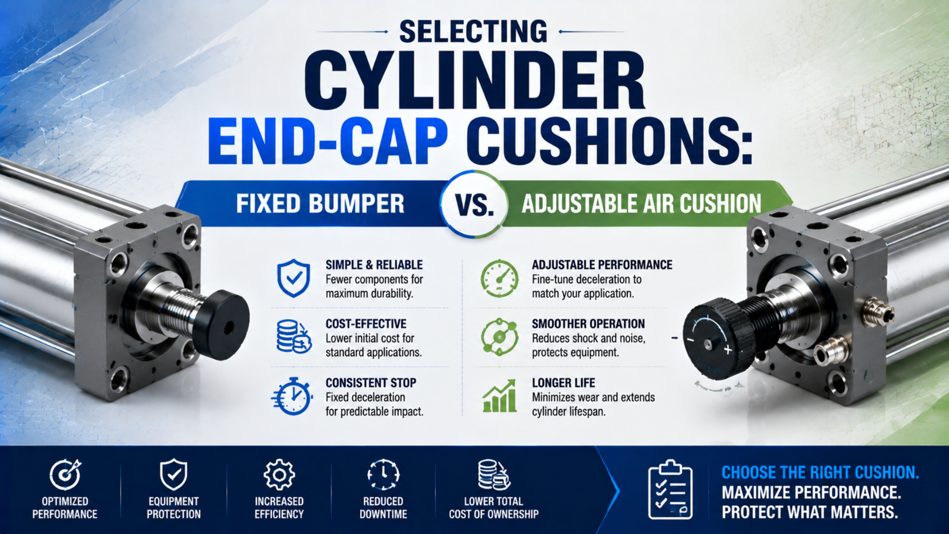
Selecting a fixed bumper vs adjustable air cushion is an energy-capacity decision, not a universal bore, load, or speed cutoff. A fixed elastomer bumper can be the correct low-complexity choice when the actual end-of-stroke energy stays within its rating. Adjustable air cushioning becomes useful when the load needs controlled deceleration and the selected cylinder provides enough cushion capacity.
Start with the real moving mass and the piston speed when cushioning begins. Then compare that operating point with the exact cylinder series, bore, stroke direction, pressure, cushion type, and manufacturer’s allowable-energy or mass-versus-speed data. If the point falls outside the published envelope, changing the needle cannot create more rated capacity.
Key Takeaways
- Parker warns that cushion-entry speed can be about 50% higher than average piston speed.
- SMC publishes different allowable cushion energies by series and bore, so no universal cutoff is defensible.
- Select, adjust, and validate each stroke direction under the worst credible production load.
Short Answer: Select From Energy and Catalog Limits
SMC lists 0.090 J for the rubber bumper and 0.18 J for the air cushion on one 16 mm CJ2 example, a 2:1 difference that applies to that listed configuration only (SMC cylinder-selection guide). The correct choice comes from the selected model’s own capacity data.
Choose a fixed bumper when the manufacturer rates it for the real end-of-stroke energy, environment, temperature, and repetition rate, and when rebound or stopping distance does not disturb the process. Its passive construction removes a commissioning adjustment, but it still needs inspection for permanent set, cracking, hardening, softening, or loss of retention.
Choose an adjustable air cushion when the application benefits from a longer, tunable deceleration phase and the exact cylinder’s cushion envelope covers the moving mass and entry speed. The needle sets exhaust restriction. It does not change piston mass, cushion length, available chamber volume, seal condition, or the structural limits of the cylinder.
Escalate to a larger cylinder, a different cushioning design, or an external shock absorber when the operating point exceeds the built-in cushion data. Keep the machine stop and load guidance separate from the cylinder cushion unless the component manufacturer explicitly combines those functions.
How Does a Fixed Bumper vs Adjustable Air Cushion Stop the Load?
Festo groups pneumatic-cylinder end cushioning into 3 broad methods: mechanical or elastic, pneumatic or servo-pneumatic, and hydraulic damping (Festo). Fixed bumpers and adjustable air cushions use different mechanisms, but either may still end with controlled contact at the physical stroke limit.
A fixed bumper is an elastomer element that compresses when the piston or carriage reaches the end region. Its formulation, hardness, geometry, preload, temperature, strain rate, and age determine how much energy it stores, returns, and dissipates. It is passive and repeatable only while those material properties remain inside their design range.
An adjustable air cushion is a pneumatic deceleration mechanism that starts acting before final contact. A cushion boss or sleeve enters a matching seal or bore, isolates a pocket of air, and forces that air through a restricted exhaust path. Closing the needle generally increases restriction; opening it reduces restriction. The manufacturer’s instructions remain authoritative because internal passages vary.
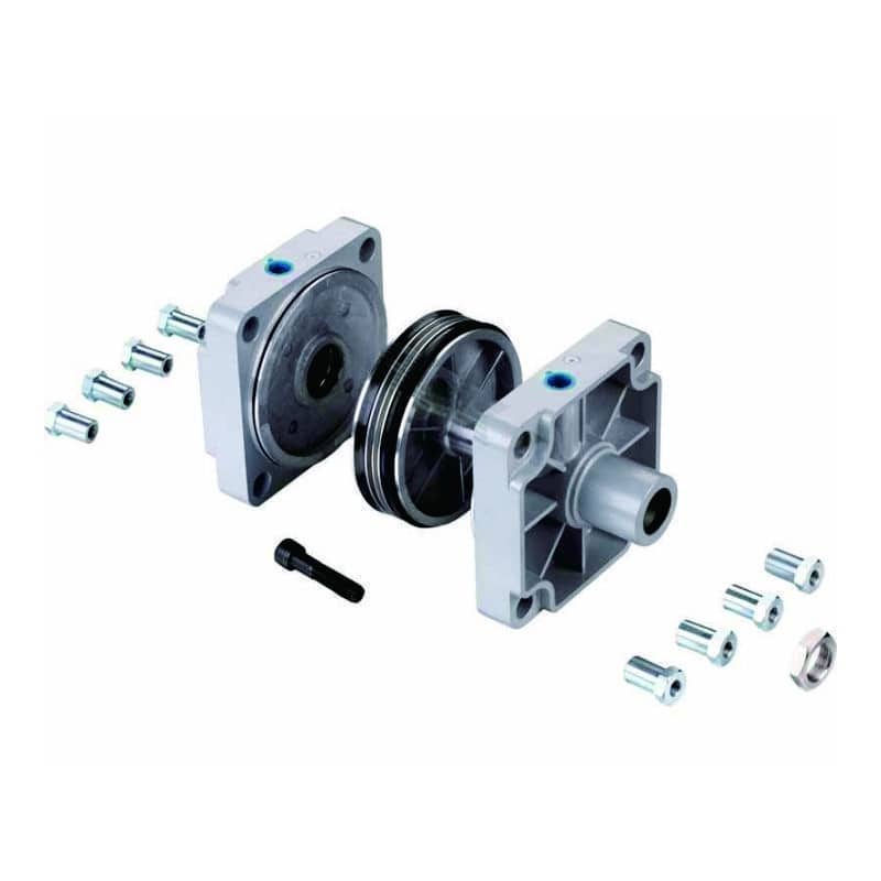
An exploded cylinder image helps identify the end covers and piston assembly, but the photograph alone cannot establish cushion type, effective cushion length, or allowable energy.
| Comparison point | Fixed elastomer bumper | Adjustable air cushion |
|---|---|---|
| Primary mechanism | Viscoelastic compression | Trapped-air pressure with metered exhaust |
| Adjustment | Normally none | Model-specific needle or screw |
| Selection authority | Bumper energy, compression, temperature, and life data | Cylinder cushion chart, pressure range, mass, and entry speed |
| Typical commissioning task | Confirm quiet, stable contact and acceptable rebound | Balance final impact, rebound, and final-stroke time |
| Common deterioration | Permanent set, cracking, hardening, softening | Seal bypass, contamination, needle drift, damaged cushion boss |
| Capacity response | Fixed by material and geometry | Tunable response inside a fixed physical capacity envelope |
For transient measurements such as peak force, rebound, and temperature, use the separate elastomer bumper versus air cushion frequency-response guide.
Inputs That Control Cylinder Cushion Selection
Parker states that piston speed at the start of cushioning is typically about 50% higher than average speed in its OSP-P selection example (Parker OSP-P catalogue). That warning makes average stroke time useful for screening, but insufficient for final cushion selection.
Record the actual moving mass, not only the payload. Include the piston and rod contribution specified by the manufacturer, tooling, carriage, adapters, cable carriers, gripper, product, and any brake housing that travels with the axis. On a rodless cylinder, the external carriage and attached load are part of the cushioned mass.
Measure or conservatively estimate speed at cushion entry. Long strokes can reach a higher peak speed than short strokes with the same average cycle time. Meter-out controls, valve flow, tubing, load direction, supply pressure, and controller timing can also produce different entry speeds on extension and retraction.
| Required input | What to record | Why it matters |
|---|---|---|
| Cylinder identity | Manufacturer, series, bore, stroke, rod or carriage configuration | Connects the calculation to the correct capacity chart |
| Cushion type | None, bumper, adjustable air, self-adjusting air, or external device | Defines the available selection method |
| Moving mass | Every part moving in that direction | Kinetic energy scales directly with mass |
| Cushion-entry speed | Extension and retraction under the real load | Kinetic energy scales with speed squared |
| Drive condition | Pressure, load force, orientation, and active valves | Air pressure or gravity may keep doing work during deceleration |
| Cushion length | Effective travel stated for the selected model | Sets the distance available to remove velocity |
| Cycle pattern | Events per minute, dwell, shifts, and bursts | Reveals heat accumulation and recovery time |
| Process requirement | Rebound, settling time, noise, position repeatability | Determines whether a technically safe stop is operationally acceptable |
| Environment | Temperature, chemicals, contamination, washdown | Changes elastomer and small-orifice behavior |
In our experience reviewing cylinder applications, entry speed is the most commonly missing input. Teams often submit bore, stroke, load, and total cycle time, then assume the average speed represents the stop. Asking for a short loaded-motion trace or a high-frame-rate video can expose acceleration, coast, and deceleration that the average conceals.
How Should Required Cushion Energy Be Calculated?
SMC uses the linear kinetic-energy relationship in its cylinder-selection guide and publishes model-specific allowable values in joules (SMC). Use the equation as a screening step, then follow the selected manufacturer’s own calculation method because some catalog limits already include assumptions that must not be counted twice.
The moving kinetic energy at cushion entry is:
Here, is kinetic energy in joules, is the moving mass in kilograms, and is cushion-entry speed in metres per second. Use direction-specific values. The retracting and extending strokes can have different mass, speed, force, and published capacity.
A conservative system review may also track drive work that continues through the cushion travel:
Here, is the net force still acting in the direction of travel in newtons, and is the effective cushion distance in metres. Pressure, load force, friction, gravity, and exhaust back pressure affect the net value.
When the supplier’s method allows the terms to be combined, a screening requirement can be written as:
The factor is an engineering allowance for variation and uncertainty. It is not a universal constant. Select it through the machine’s risk assessment, measurement confidence, load variation, duty cycle, and the component manufacturer’s instructions.
Consider a hypothetical 12 kg moving assembly entering the cushion at 0.8 m/s. If the net drive force through a 25 mm cushion distance is estimated as 100 N, the screening calculation is:
With an illustrative allowance of 1.25, the combined screening value is:
This is a worked calculation, not a customer result or a universal acceptance limit. Do not compare 7.93 J directly with a catalog value unless the catalog uses the same energy definition, load convention, pressure assumption, and stroke direction. When the manufacturer specifies a mass-versus-speed envelope instead, plot the operating point on that envelope.
The kinetic-energy calculation guide explains mass and velocity inputs in more detail. The load-mass versus velocity cushion chart guide covers model-specific envelope reading.
When Is a Fixed Bumper the Better Specification?
Festo describes elastic damping as suitable for relatively low-speed, low-load, or short-stroke service, while SMC’s listed 16 mm CJ2 rubber-bumper example permits 0.090 J (Festo; SMC). Use that figure only to show why the exact series matters, not as a family-wide threshold.
A fixed bumper is attractive when the catalog confirms adequate energy capacity and the process accepts its stopping behavior. Typical uses include short movements of light tooling, compact mechanisms, sensor flags, small gates, and applications where an exposed adjustment screw would create an unwanted maintenance or hygiene variable.
Select the bumper from its stated conditions. Temperature can change stiffness and rebound. Oils, coolants, cleaners, ozone, and hydrolysis can change the material. High repetition can build heat before the bumper recovers. Compression set may gradually reduce effective travel even when the bumper has not visibly cracked.
Fixed does not mean maintenance-free. Inspect the bumper for permanent deformation, extrusion, cracking, surface tack, hardening, looseness, and material transfer. Record whether impact sound, rebound, settling time, or mounting movement changes at full production speed.
Use a fixed bumper only when all of these statements are true:
- the exact bumper or cylinder has published capacity data for the operating condition;
- both stroke directions remain inside the relevant limit;
- rebound and final position meet the process requirement;
- temperature, chemicals, contamination, and cycle rate are compatible;
- the cylinder mount and machine stop are not being used beyond their ratings;
- a foreseeable speed, payload, or pressure increase will not erase the required margin.
The simplicity advantage is real only when the process window is narrow. A passive bumper avoids adjustment drift, but it cannot adapt when operators change payloads, pressure, or speed. If the machine has multiple recipes, evaluate every recipe rather than approving the bumper from the lightest product.
When Does an Adjustable Air Cushion Add Useful Control?
In the same SMC CJ2 example, the 16 mm air cushion is listed at 0.18 J compared with 0.090 J for the rubber bumper (SMC). That model-specific difference illustrates added capacity, while the needle provides control over how trapped air is exhausted during the final travel.
Adjustable air cushioning is useful when the selected model covers the energy and the process needs control over final impact, rebound, settling time, or noise. It often fits higher moving energy, longer strokes, faster entry speeds, fragile payloads, and machines where the two travel directions need different settings.
The adjustment is not a capacity upgrade. If the needle is too open, pressure may not rise soon enough and the piston can hit the final bumper or cap hard. If it is too closed, the piston may decelerate too early, rebound, stall before the sensor, or crawl through the last part of the stroke.
Air-cushion behavior also depends on the complete exhaust path. A restricted valve port, undersized fitting, blocked silencer, long tube, common manifold exhaust, or downstream back pressure can change the apparent needle response. Diagnose those restrictions before blaming the cushion mechanism.
Choose adjustable air cushioning when:
- the manufacturer provides a mass-versus-speed or allowable-energy envelope that covers the application;
- the effective cushion length and pressure range match the operating condition;
- commissioning access is safe and the final setting can be locked or controlled;
- production variation remains inside the adjustment range;
- maintenance can inspect cushion seals, the needle, the check path, and contamination-sensitive passages;
- the process benefits from controlled deceleration more than it benefits from a sealed, adjustment-free design.
The high-speed cylinder air-cushion guide covers velocity-driven applications. Use the cushion-seal engineering guide when pressure bypass or one-direction engagement is the main concern.
Built-In Cushioning Has a Defined Limit
SMC instructs users to consider a larger bore or an external stopper when kinetic energy exceeds the built-in cushion value, while Parker requires additional shock absorbers when its mass-versus-entry-speed limits are exceeded (SMC; Parker). A harder needle setting is not a substitute for more capacity.
Use an external industrial shock absorber when it is rated to remove the required energy at the actual impact speed and event rate, and when the machine structure can carry the resulting reaction force. Its mounting position matters. On guided or rodless axes, placing the absorber far from the moving centre of gravity can add pitch, yaw, or roll moments.
A separate mechanical stop may be necessary when the cylinder’s internal end position is not intended to establish machine accuracy or resist external load. The stop, frame, fasteners, and contact geometry then require their own force, fatigue, and alignment checks.
The decision is not always either-or. Some cylinders use pneumatic cushioning followed by an elastomer element at final contact. Others use built-in cushioning plus an external shock absorber because the external device manages high energy while the cylinder cushion controls residual movement.
How Should an Adjustable Cushion Be Commissioned Safely?
OSHA 29 CFR 1910.147 explicitly includes pneumatic energy among hazardous energy sources and requires covered servicing work to control unexpected startup or stored-energy release (OSHA). Powered observation and isolated inspection are different tasks, so the machine’s approved procedure must define which condition applies.
Do not assume a universal starting position such as 1.5 turns open. Needle design, thread pitch, usable travel, factory preset, cylinder bore, pressure, and cushion geometry differ. Start from the exact manufacturer’s commissioning instructions and record the supplied position before making a change.
Use this controlled sequence:
- Verify the cylinder series, cushion option, load, pressure, speed-control orientation, and external exhaust path.
- Establish a safe observation method with guards and exclusion zones in place.
- Begin at reduced speed or pressure only when the manufacturer and machine risk assessment permit it.
- Observe extension and retraction separately under the intended load.
- Make one small, documented adjustment to one end.
- Run enough cycles to see repeatability, then record final impact, rebound, settling, sound, pressure, and stroke time.
- Increase toward the worst credible production condition in controlled steps.
- Lock or protect the final setting where the design provides that feature.
- Apply the approved energy-isolation procedure before inspection, cleaning, disassembly, or seal work.
Do not close the cushion valve completely unless the manufacturer explicitly instructs it. A fully restricted cushion can create high pressure, rebound, or incomplete travel. A hard stop with the needle nearly closed may indicate excess energy, seal bypass, a damaged cushion boss, or an external exhaust problem rather than insufficient adjustment.
If a cylinder has already developed a hard impact, slow final crawl, one-end-only fault, or unstable setting, use the cylinder cushion failure diagnostic guide before ordering parts.
RFQ and Acceptance Checklist
Parker identifies moving mass and piston speed at the start of cushioning as 2 main inputs for its pneumatic end-cushion selection chart (Parker). A useful RFQ adds direction, pressure, cushion travel, cycle pattern, environment, process response, and the evidence needed to connect the application to one exact cylinder.
Include these fields in the request:
- Cylinder identity: standard, manufacturer, series, bore, stroke, rod size, mounting, and orientation.
- Cushion option: fixed bumper, adjustable air cushion, self-adjusting cushion, or external device at each end.
- Moving mass: payload, tooling, carriage, adapters, product, cable carrier, and other moving hardware.
- Motion data: cushion-entry speed for extension and retraction, plus the measurement or estimation method.
- Force condition: working pressure, opposing load, gravity direction, friction estimate, and external forces.
- Cushion travel: effective length for each end and the manufacturer’s definition.
- Duty: cycles per minute, burst duration, dwell, shifts, and expected recipe changes.
- Process limit: acceptable impact, rebound, settling time, noise, and final-position behavior.
- Environment: temperature, contaminants, chemicals, washdown, dust, and lubricant restrictions.
- Capacity evidence: catalog page, mass-versus-speed chart, allowable energy, assumptions, and required margin.
- External damping: shock-absorber model, energy rating, event rate, stroke, mounting, and reaction path.
- Commissioning record: factory setting, final needle positions, production test condition, and acceptance results.
Treat each end as a separate selection line. Extension and retraction can have different effective piston area, speed, gravity contribution, payload geometry, external stop, and exhaust path. A single statement that the cylinder is “air cushioned” hides the direction that is most likely to exceed its limit.
The final acceptance record should identify the exact part number and configuration, not only the cylinder family. If a supplier substitutes the cushion option, bore, rod, seal package, end cover, or external shock absorber, repeat the capacity check before approving the change.
Cylinder End-Cap Cushion FAQs: What Should Buyers Ask?
SMC describes 2 built-in cushion categories in its general selection guide, rubber bumpers and air cushions, while Festo describes 3 broader damping methods that also include hydraulic damping. These FAQs keep those classifications separate from model-specific capacity, retrofit feasibility, needle settings, external stops, and field acceptance.
Is there a universal speed or bore threshold for choosing an air cushion?
No. Bore and speed influence the result, but the selection also depends on moving mass, cushion-entry speed, pressure, force direction, effective cushion length, cycle pattern, and the exact model’s published capacity. Use the manufacturer’s allowable-energy or mass-versus-speed data for each end rather than a generic 300 mm/s or 32 mm cutoff.
Can an adjustable air cushion be retrofitted to a fixed-bumper cylinder?
Only when the manufacturer offers an approved conversion for that exact cylinder. Adjustable cushioning may require a different piston, cushion boss, seal, end cover, needle assembly, check path, and machining. Replacing an end cap alone does not establish compatibility, pressure integrity, cushion engagement, or the original cylinder’s rated performance.
What is the correct starting position for a cushion needle?
Use the selected manufacturer’s commissioning instructions and factory setting. There is no universal number of turns because needle geometry, thread pitch, usable travel, bore, cushion volume, and pressure differ. Record the original position, change one end in small increments, and validate impact, rebound, final travel, and repeatability under the actual load.
Does an air cushion replace a mechanical stop?
Not automatically. An air cushion decelerates the piston near the end of stroke, but the cylinder’s internal end position may not be rated as the machine’s precision datum or as a stop for external forces. Specify a separate mechanical stop when the machine needs defined position, load restraint, or structural reaction outside the cylinder rating.
When is an external shock absorber required?
Use an external shock absorber or another engineered stopping system when the operating point exceeds the built-in cushion envelope, the process needs a longer controlled stop, or the cylinder should not carry the reaction load. Size the device for energy per event, impact speed, event rate, stroke, temperature, mounting position, and machine structure.
Sources and technical references
- Festo: Cylinder cushioning, the three most common methods, elastic, adjustable pneumatic, self-adjusting pneumatic, and hydraulic damping context. Retrieved 2026-07-27.
- SMC: Air Cylinder Selection Technical Data, kinetic-energy equation, model-specific rubber-bumper and air-cushion values, and external-stop guidance. Retrieved 2026-07-27.
- Parker: OSP-P Linear Drive System Catalogue, moving-mass and cushion-entry-speed selection, the approximate 50% entry-speed warning, and external shock-absorber boundary. Retrieved 2026-07-27.
- OSHA 29 CFR 1910.147, control of hazardous pneumatic and other stored energy during covered servicing and maintenance. Retrieved 2026-07-27.