

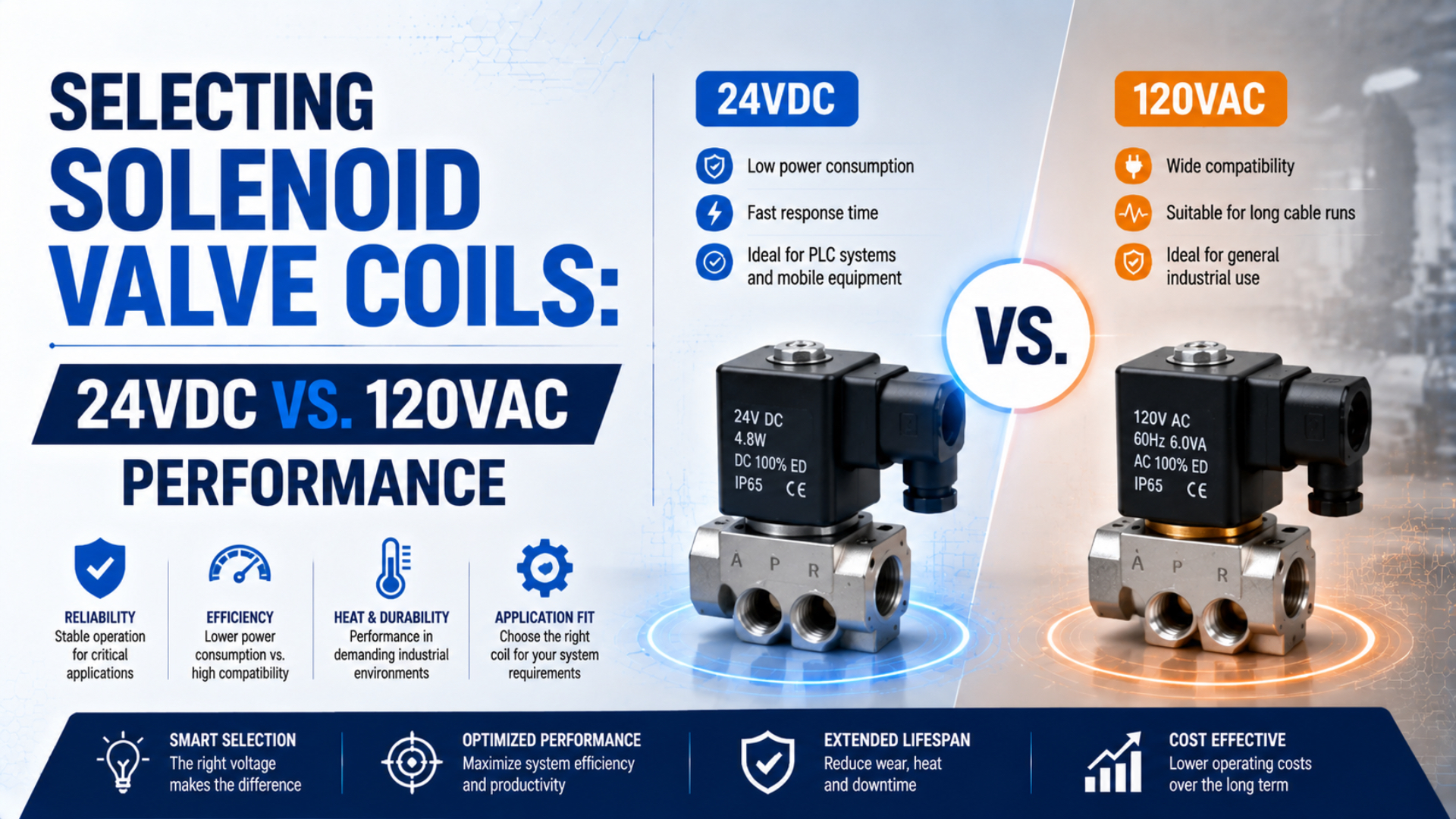
Solenoid coil voltage selection is the approval of the complete electrical interface, not a contest over which voltage is universally faster, cooler, or more reliable. The comparison of 24VDC vs 120VAC solenoid valve coils begins with the installed supply and output device, then moves to the exact coil and valve data.
The decision still depends on the exact coil and valve combination. Check rated voltage, AC frequency, permissible voltage range, pickup and holding load, output-device capacity, suppression, duty, connector, and ambient limits before approving either option.
Key Takeaways
- Voltage alone does not determine valve flow, pressure rating, or response time.
- Compare AC pickup and holding VA with documented DC electrical data.
- Measure loaded voltage at the coil under the worst credible simultaneous command, then verify suppression, temperature, energized duty, and release behavior.
- A voltage change is an electrical redesign.
Which Coil Voltage Is the Better Starting Point?
An SMC SY-series catalog lists DC and AC coils in one valve family, with configuration-specific voltage ranges, power values, suppressors, and response times (SMC SY series catalog, accessed 2026). Start with the available control architecture, then approve the exact configured valve.
Choose 24VDC as the starting point when the machine has a documented 24VDC load supply and a transistor output that can drive the coil. This arrangement can simplify diagnostics because the controller, sensors, and valve outputs share one control-voltage layer. It also avoids adding an interposing device merely to switch line-voltage AC.
Choose 120VAC when the machine already supplies 120VAC at the valve circuit, the switching device is rated for the coil’s AC pickup and holding load, and the installed electrical design permits that voltage. A like-for-like AC replacement may be less disruptive than adding a DC power supply, new protection, revised wiring, and a different output interface.
Do not make the selection from the connector shape. Two coils can share the same physical envelope while differing in winding, frequency, power, polarity, suppression, temperature rating, or approved operator. Likewise, the term “DIN connector” does not prove the pinout, gasket, indicator, earth connection, or suppression circuit matches.
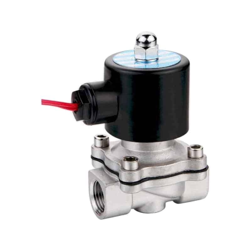
Fast selection matrix
| Installed condition | Better starting point | Required confirmation |
|---|---|---|
| 24VDC transistor output | 24VDC coil | Per-point current, group current, on-state drop, leakage, diagnostics, and suppression |
| Existing 120VAC relay circuit | 120VAC coil | Pickup VA, holding VA, contact rating, frequency, branch protection, and suppression |
| Battery-powered or mobile control | Matching DC coil | Actual battery range, transient limits, current, and environmental rating |
| Fieldbus valve manifold | Manufacturer-specified coil/electronics | Manifold part code, node capacity, polarity, current budget, and permitted stations |
| Safety-related machine function | Risk-assessed architecture | Device suitability, diagnostics, de-energized state, isolation, and validation |
| Unknown or unreadable coil label | Neither until identified | Wiring drawing, measured supply, valve part code, and manufacturer documentation |
In our experience, the selection object is more than “24VDC” or “120VAC.” It includes the coil, operator, connector, suppression network, output channel, supply branch, and operating environment as one approved configuration. Changing any member of that chain can change pickup, release, diagnostics, temperature, or fault behavior.
Electrical Interface Differences Between 24VDC and 120VAC
ASCO Series 320 data separates DC watts from AC watts, holding VA, and inrush VA. Its AC examples use 25 VA holding and 40 to 70 VA inrush; those are model-specific values, not universal multipliers (ASCO Series 320 catalog, accessed 2026).
A passive DC coil has an inductive current rise followed by a steady condition governed mainly by the loaded terminal voltage, winding resistance, and winding temperature. It is not a constant-current device unless a driver regulates the current. The controller output must handle the real current while keeping the voltage at the coil inside its documented range.
AC pickup and holding are separate load states: Pickup VA is the apparent-power demand while the armature moves toward its seat. Holding VA is the lower demand after the magnetic circuit closes, so check the output device and protection against both conditions.
AC frequency is part of the coil rating. Emerson, for example, identifies one replacement coil as 110VAC at 50Hz or 120VAC at 60Hz rather than treating voltage and frequency as separate afterthoughts (ASCO ZB12A coil data, accessed 2026). Some coils accept both frequencies; others have different ratings. Read the complete nameplate.
| Electrical property | 24VDC review | 120VAC review |
|---|---|---|
| Supply | Loaded DC voltage and ripple | RMS voltage, frequency, and transformer regulation |
| Coil load | Rated current or watts; peak-and-hold data if applicable | Pickup VA, holding VA, watts, and frequency |
| Output device | Transistor type, sourcing/sinking, current and leakage | Relay, contactor, triac, or SSR AC-load rating |
| Interruption transient | Approved diode, TVS, or driver clamp | Approved MOV, RC network, suppressor module, or manufacturer circuit |
| Polarity | Relevant with LEDs, diodes, and electronic coils | Usually not applicable to a bare AC winding, but connector electronics can change this |
| Diagnostics | Off-state leakage and test pulses | SSR/triac leakage, relay monitoring, and residual voltage |
Can the Control Output Carry the Coil Load?
Siemens rates one S7-300 module for 24VDC, 2A outputs suitable for solenoid valves and defines its isolation, protection, switching frequency, and inductive-load behavior (Siemens module data, 2022). This rating is not universal; approve each coil against its exact output-module manual.
Group limits matter. For 24VDC, check current per point and total current per output group, connector, and common return. Also review on-state voltage drop, off-state leakage, diagnostic pulses, short-circuit behavior, and ambient derating. A nominally compatible coil can still fail when the channel cannot deliver pickup current or the remote cable loses too much voltage.
For 120VAC, check relay or solid-state output ratings for the actual inductive load. A relay contact must tolerate pickup current and switching duty. A triac or AC solid-state relay can leave residual current when nominally off, which may turn on a connector indicator, confuse diagnostics, or prevent a low-power coil from releasing cleanly.
Simultaneous commands deserve a separate check. A manifold may energize several coils during startup, recipe changes, fault recovery, or a coordinated motion sequence. Add the credible concurrent loads, then verify the power supply or control transformer, protective device, terminals, common conductors, output group, and connector.
Measure under load. Loaded coil voltage is the voltage at the energized coil terminals during a defined command condition. Record it with controller-supply voltage during the worst credible command pattern. The difference reveals supply sag, output-device drop, connector resistance, and cable loss that a no-load cabinet measurement cannot show.
How Does Suppression Affect Release and Output Protection?
The SMC SY catalog reports different response limits for some variants with and without surge suppression, and identifies diode or varistor protection according to connector and voltage configuration (SMC SY series catalog, accessed 2026). Suppression is therefore part of the timing specification, not an accessory selected after the valve.
Interruption creates a transient. When a DC coil is switched off, the collapsing field makes the winding attempt to maintain current. A basic flyback diode protects the transistor through a low-voltage path, but slower current decay can delay release. An approved TVS, Zener clamp, or driver can permit a higher controlled clamp voltage and faster decay, subject to the output rating.
Do not place a conventional flyback diode directly across an AC winding. It conducts on one half-cycle and is not a valid raw-AC suppression method. AC applications commonly use a manufacturer-approved varistor, RC network, or connector module. Rectified or electronically controlled coils are different again, so use their circuit diagram rather than inferring the internal design from the voltage label.
Polarity also changes with accessories. A bare passive DC winding may be non-polar, but an LED, diode, bridge rectifier, or electronic economizer can impose polarity or connector requirements. Reverse wiring might prevent operation, defeat the indicator, or damage the suppression circuit even when the coil voltage is correct.
If release time affects a clamp, diverter, reject gate, or synchronized cylinder, record the complete command-to-event chain. The related guide on measuring pneumatic solenoid valve response time separates coil current decay, valve shift, port-pressure change, and actuator arrival.
Does Coil Voltage Determine Valve Speed, Flow, or Heat?
SMC publishes configured response at stated pressure and temperature; ASCO assigns electrical loads by operator and valve series (SMC catalog, accessed 2026; ASCO catalog, accessed 2026). Neither source ranks 24VDC as inherently faster or cooler than 120VAC.
A fully shifted valve has a defined pneumatic path. Its orifice, spool geometry, ports, seals, and pressure conditions govern capacity. Changing only the approved coil-voltage option does not create a larger Cv or raise the valve body’s pressure rating. Incorrect voltage can prevent complete shifting, but that is an electrical fault, not a new flow specification.
Valve response includes more than coil pickup. Pilot pressure, armature travel, spool or poppet motion, exhaust restriction, tubing volume, actuator load, and sensor location can dominate the observed delay. Use the dedicated AC versus DC response-time analysis when timing is the primary question.
Heat is also configuration-specific. Winding power, energization time, adjacent coils, connector electronics, valve-body conduction, airflow, ambient temperature, and media temperature all contribute. A low-wattage DC coil can overheat outside its voltage or temperature range, while a properly applied AC coil can operate within its published thermal limits.
For current-regulated designs, Texas Instruments’ DRV110 separates peak current, keep time, hold current, and PWM frequency, then reduces current after pull-in to lower steady power and thermal dissipation (Texas Instruments DRV110 datasheet, 2016). That behavior cannot be described by one passive-coil wattage value.
Read the companion articles on solenoid voltage tolerance and energy-saving coil wattage instead of compressing those separate engineering questions into a voltage ranking.
What Must Be Verified Before Replacing a Coil?
An ASCO coil example identifies voltage type, 110V/50Hz and 120V/60Hz values, coil class, ambient range, and watt rating as separate fields (ASCO ZB12A coil data, accessed 2026). A complete replacement record must preserve that level of detail rather than reducing the requirement to connector shape and nominal voltage.
Start with the complete valve and coil part numbers. Photograph the nameplate before removal, obtain the manufacturer’s part-code decoder, and compare the configured operator, winding, connector, indicator, suppression, enclosure, temperature range, duty, and approvals. Confirm that the replacement coil is approved for the installed valve operator.
Then inspect the machine circuit:
- Record the supply voltage and AC frequency from the drawing and protective-device schedule.
- Identify the output module, relay, triac, SSR, or contactor and its exact load rating.
- Confirm connector pinout, cable entry, protective earth, gasket, polarity, and suppression.
- Measure loaded voltage at the coil during the maximum credible simultaneous command, including startup, fault recovery, and any operating state that energizes several valves on the same output group or supply branch.
- Compare pickup, holding, and continuous load against the output point, group, supply branch, and common return.
- Check ambient temperature, media temperature, adjacent energized coils, energized duty, and enclosure conditions.
- Verify the de-energized valve state and what the actuator must do after power or air loss.
- Record acceptance limits for current, temperature, shift, release, leakage, and final actuator response, including the instruments, test conditions, and person authorized to approve or reject the installation.
When the old label is unreadable, measuring voltage is necessary but not sufficient. A meter may identify 24VDC or 120VAC, yet it cannot reveal the approved frequency pairing, coil class, pickup VA, suppression circuit, duty, environmental rating, or operator compatibility. Recover the valve identity and machine documentation before ordering.
For a complete cross-brand review, use the broader OEM solenoid valve compatibility checklist. It adds function, pneumatic interfaces, flow, pressure, materials, environment, and fault-state validation to the electrical checks in this article.
Installed-Coil Commissioning Procedure
IEC 60204-1 applies to machine electrical and programmable equipment, including control-circuit protection, documentation, protective bonding, and related safety concerns (IEC 60204-1, 2016). It supports treating coil commissioning as part of the machine electrical system rather than as an isolated bench check.
Isolate hazardous electrical and pneumatic energy before wiring or resistance checks. Use the machine’s approved procedure and qualified personnel. A 24V label does not by itself prove a circuit is SELV or PELV, and 120VAC presents hazardous shock exposure that requires suitable enclosure, isolation, protection, and test practices.
Commission under controlled conditions:
- With power isolated, verify the exact part code, connector, pinout, suppression, earth, gasket, mounting, and coil retention.
- Energize at approved pressure and record supply voltage, voltage at the coil, current or AC load, ambient temperature, and initial valve action. Compare each result with a prewritten acceptance limit instead of relying on whether the valve merely clicks.
- Test the maximum credible simultaneous valve command and watch for supply sag, output faults, nuisance trips, connector heating, or delayed shifting.
- Confirm release behavior, including the actuator result after command removal, electrical power loss, and pneumatic supply loss.
- After thermal stabilization under representative duty, compare coil and connector temperature with the manufacturer’s limits and the approved baseline.
- Save the installed part number, readings, wiring revision, test conditions, acceptance limits, and approver in the maintenance record.
A successful click is not a commissioning result. The useful evidence connects the electrical command to coil voltage and current, valve shift, port pressure, actuator arrival, and de-energized behavior. That sequence distinguishes an electrical mismatch from a sticky operator, weak pilot supply, restricted exhaust, or actuator problem.
If a replacement runs hot, buzzes, drops out, or shifts inconsistently, follow the solenoid coil burnout root-cause guide before fitting another coil. Repeated failure usually means the circuit, operator, environment, or installation condition remains unresolved.
Solenoid Coil FAQs: 24VDC and 120VAC Selection
SMC and ASCO treat voltage, frequency, range, power, suppression, and response as separate specifications (SMC SY catalog, accessed 2026; ASCO 320 catalog, accessed 2026). Neither publishes a generic AC/DC ranking. These answers address common replacement questions.
Can a 24VDC coil replace a 120VAC coil if it fits physically?
No. The 24VDC coil needs a compatible DC supply, switching output, protection, polarity arrangement, and wiring. Applying 120VAC can destroy it; feeding 24VDC into a 120VAC coil will usually provide insufficient actuation, so treat the change as a controlled electrical redesign and verify that the valve operator is approved for the new coil.
Is a 24VDC solenoid valve always faster than a 120VAC valve?
No. Pickup and release depend on the winding, magnetic circuit, armature, driver, suppressor, valve mechanism, pressure, and test conditions. AC can have substantial pickup inrush while a low-voltage flyback diode can delay DC release, so compare manufacturer data for the configured valve and confirm the required event on the machine.
Can a PLC output drive any 24VDC solenoid coil directly?
No. Match coil current and pickup behavior to the output’s per-channel and group limits, voltage drop, leakage current, diagnostic pulses, switching frequency, protection, and ambient derating. Also verify sourcing or sinking logic and the permitted suppression circuit. A matching nominal voltage alone does not establish electrical compatibility.
Why does a 120VAC coil buzz or run hot?
Possible causes include incorrect voltage or frequency, incomplete armature seating, contamination, a damaged shading component, excessive ambient temperature, overvoltage, wrong coil/operator pairing, or abnormal duty. Some AC sound can be product-specific, but a new or increasing buzz warrants isolation, inspection, loaded-voltage measurement, and comparison with the manufacturer’s limits.
Sources and technical references
- SMC Corporation, Series 10-SY3000/5000/7000/9000 5 Port Solenoid Valve. Voltage ranges, AC/DC electrical data, suppression, and configured response times. Accessed July 27, 2026: SMC SY catalog.
- Emerson ASCO, Series 320 General Service Solenoid Valves. DC watts and AC watts, holding VA, inrush VA, voltage, frequency, and ambient examples. Accessed July 27, 2026: ASCO Series 320 catalog.
- Emerson ASCO, ZB12A Coil. Voltage/frequency pairing, coil class, watt rating, and ambient range. Accessed July 27, 2026: ASCO ZB12A coil data.
- Siemens, S7-300 Module Data. Output-channel and inductive-load specifications for a specific 24VDC digital-output module. Accessed July 27, 2026: Siemens module manual.
- Texas Instruments, DRV110 Current Controller for Solenoids, Relays, and Valves. Peak current, keep time, hold current, PWM control, and thermal-reduction architecture. Accessed July 27, 2026: DRV110 datasheet.
- International Electrotechnical Commission, IEC 60204-1:2016, Safety of machinery, Electrical equipment of machines, Part 1. Accessed July 27, 2026: IEC 60204-1.