

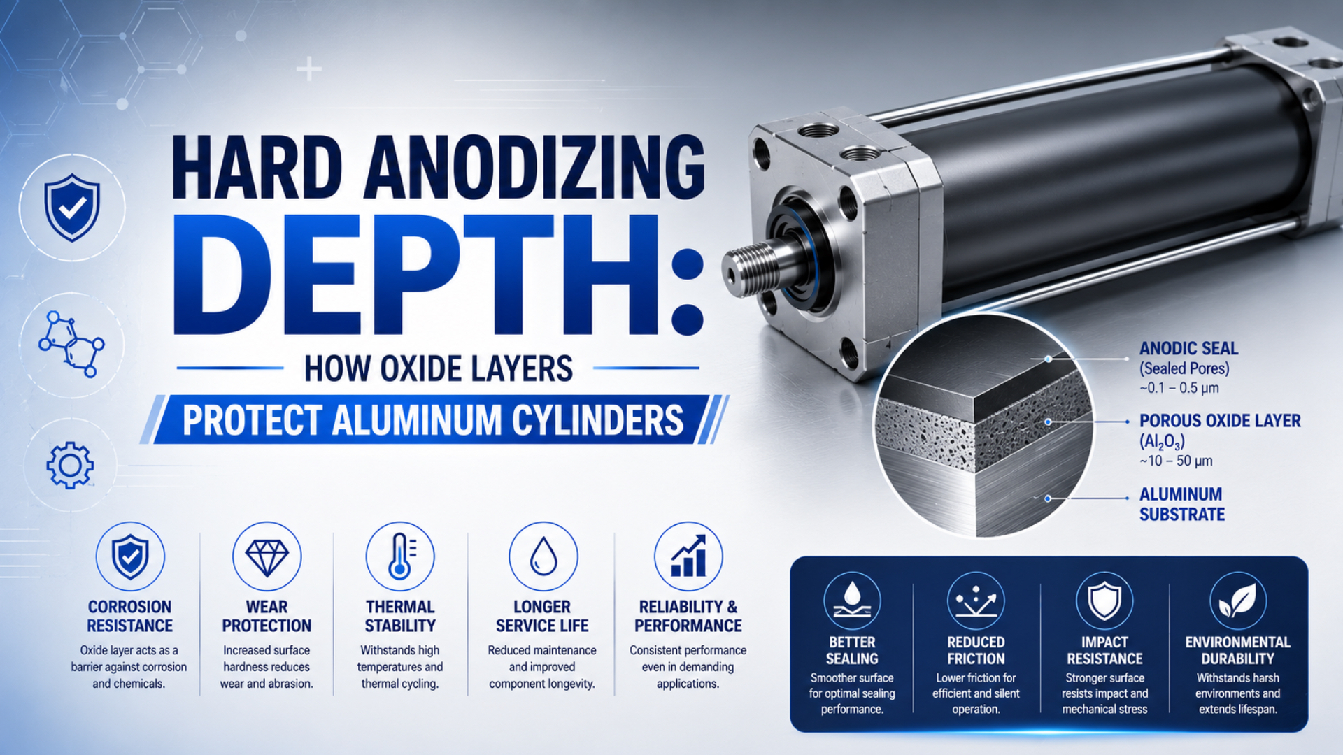
Hard anodizing protects an aluminum cylinder only when coating thickness, alloy, dimensional growth, sealing, surface finish, and verification tests are specified together. A thicker oxide layer can provide more wear reserve, but thickness alone cannot predict cylinder life. The protected surface and its failure mode determine what the drawing should require.
MIL-PRF-8625F Amendment 2 uses 0.002 in, about 50.8 µm, as the nominal Type III thickness when a contract or drawing does not state another value. It also permits a ±20% thickness variation at or below that nominal value (DLA ASSIST, 2020). That is a procurement reference, not a universal pneumatic-cylinder optimum.
Key Takeaways
- Type III’s 50.8 µm default is a specification reference, not a life guarantee.
- Coating growth changes both outside diameters and coated bores.
- Hardness cannot substitute for abrasion or corrosion testing.
- Specify the alloy, treated surfaces, sealing, final dimensions, and acceptance method.
What Does “Hard Anodizing Depth” Actually Specify?
ISO 10074:2021 specifies requirements and test methods for hard anodic oxidation coatings on aluminum and its alloys. It does not define one cylinder-life multiplier. In engineering drawings, hard anodizing depth should therefore mean a measurable coating thickness tied to named surfaces, tolerances, post-treatment, and functional tests.
Anodizing converts aluminum at the surface into an anodic oxide coating. Part of the coating grows into the original metal boundary and part builds outward. Calling it an integral conversion layer is useful, but it should not be described as indestructible. The finished layer can still crack, wear through, or lose function when the substrate, geometry, load, counterface, or process is unsuitable.
The Aluminum Anodizers Council reports a broad hardcoat range of 0.001 to 0.005 in, equivalent to about 25.4 to 127 µm (AAC Anodized Aluminum FAQ, accessed 2026). That range shows what processes may produce. It does not tell an engineer which thickness a barrel, end cap, guide surface, or mounting face needs.
| Requirement on a drawing | What it controls | What it does not prove |
|---|---|---|
| Type III or ISO 10074 hard anodizing | Coating family and applicable requirements | Installed cylinder life |
| Nominal thickness and tolerance | Oxide amount at defined locations | Wear rate under contamination |
| Sealed or unsealed condition | Pore treatment and performance emphasis | Compatibility with every cleaner |
| Final machined dimension | Assembly clearance after processing | Surface texture along the full seal path |
| Abrasion or corrosion test | Performance under the stated method | Every field environment |
Treat coating thickness as one controlled input. Service life is an output of the complete contact system.
Why Is Thickness Alone Not a Life Prediction?
The AAC hardcoat guideline separates six application functions and assigns different tests to corrosion, wear, color, adhesion, dielectric, and high-temperature duties. It also states that hardness results cannot prove wear resistance (AAC Hard Anodic Oxide Guideline, 2024). A thickness-to-years table therefore has no general engineering basis.
Wear depends on more than oxide depth. Abrasive particles must first reach the moving interface. Contact pressure, particle hardness, seal lip geometry, lubricant condition, counterface finish, side load, and stroke frequency then influence how quickly damage accumulates. A thicker coating may delay substrate exposure, yet it cannot correct poor guidance or contaminated air.
Corrosion is also application-specific. An unsealed hardcoat selected for maximum abrasion resistance does not behave like a sealed coating selected for corrosion exposure. MIL-PRF-8625F requires unsealed Type III coatings for its abrasion test and makes sealing a specified choice when corrosion resistance is needed and reduced abrasion resistance is acceptable (MIL-PRF-8625F, 2020).
This is why a pneumatic cylinder exposed to grinding dust needs a different validation plan from one exposed to alkaline washdown. The first may prioritize particle exclusion, scraper design, and abrasion testing. The second needs chemical compatibility, sealing choice, crevice review, and a corrosion test that represents the cleaning chemistry. For a broader contamination strategy, see the foundry actuator protection guide.
Avoid these unsupported shortcuts:
- Do not assign a fixed percentage of added life to each additional micrometre.
- Do not translate a hardness value directly into cylinder cycles or years.
- Do not assume a darker coating is thicker, harder, or more wear-resistant.
- Do not specify “maximum thickness” without checking fits, threads, edges, and fatigue-sensitive geometry.
How Does Coating Growth Change Cylinder Dimensions?
The AAC describes approximately half inward and half outward growth as a Type III rule of thumb, while warning that alloy and process conditions change dimensional results (AAC Anodized Aluminum FAQ, accessed 2026). For a 50 µm coating, that rule predicts about 25 µm radial buildup on each coated surface.
Let be total oxide thickness normal to one surface, and let be the fraction that builds outward from the original metal boundary. The outward buildup on one surface is:
Here, and use the same length unit. The fraction is a process assumption that should be confirmed with the anodizer, not copied blindly from a generic rule.
For an outside diameter coated around its circumference, buildup occurs on both sides of the diameter:
For a coated bore, the same radial buildup projects into the hole from both sides:
If and the approved process uses , the calculated outside-diameter increase is 50 µm. A coated bore decreases by 50 µm. The earlier machining allowance must target the final post-anodize dimension, including coating tolerance and any finishing operation.
| Example feature | Pre-anodize size | Assumed coating | Predicted final size |
|---|---|---|---|
| Outside diameter | 50.000 mm | 50 µm, half outward | 50.050 mm |
| Internal bore | 50.000 mm | 50 µm, half outward | 49.950 mm |
| Radial clearance between two coated members | Application-specific | Both surfaces contribute | Calculate from both final sizes |
The arithmetic is simple. Controlling the real part is harder because edges, blind holes, electrical contact locations, alloy chemistry, racking, and local current density can change coating distribution.
Cylinder Bore and Exterior Need Separate Decisions
Parker’s C41 pneumatic-cylinder documentation states that its aluminum barrel is anodized externally and internally to improve wear and sliding properties (Parker C41 Cylinders, accessed 2026). This documented manufacturer example disproves any universal rule that cylinder bores are never anodized in pneumatic service.
Some designs use an anodized bore as the seal-running surface. Others use a different tube material, liner, coating, or finishing sequence. A mechanically coupled rodless cylinder adds a longitudinal slot, internal sealing band, external cover band, carriage load path, and local edges. Those features change both processing and inspection access.
The exterior has another job. It may face humidity, cleaners, salt, impact, fixtures, sensor brackets, or abrasive dust without serving as a dynamic sealing track. Treating every surface identically can waste cost or create avoidable dimensional risk. Masking may be appropriate for threads, bearing seats, electrical contact points, critical fits, or areas finished by another operation.
One cylinder can need two anodizing decisions: a tribology decision along the seal path and an environmental decision on exposed surfaces. The drawing should name both zones instead of placing one blanket note on the part.
Surface texture remains a separate requirement. Coating thickness does not show whether the bore has axial scratches, sharp peaks, waviness, poor roundness, or unsuitable finish for the selected seal. Use the Ra and Rz cylinder-barrel guide to define the measurement method with the seal supplier’s limits, then coordinate any post-process work with the cylinder barrel honing guide.
How Should Alloy, Sealing, and Surface Finish Be Specified?
The AAC guideline says the customer and anodizer should agree on substrate pretreatment for openings and threaded holes, and should discuss the aluminum alloy before production (AAC Hard Anodic Oxide Guideline, 2024). The same nominal thickness can perform differently on different alloys and geometries.
Start with the base material designation and temper. Alloying elements influence coating formation, appearance, attainable properties, and process response. A drawing that says only “aluminum, hard anodize” leaves too many variables open for a precision pneumatic component.
Then choose sealed or unsealed condition from the duty. An unsealed Type III coating is the reference condition for maximum abrasion performance under MIL-PRF-8625F. Sealing may improve corrosion behavior, but it can change abrasion performance. State the functional priority and the permitted process instead of requesting every benefit at its maximum.
Finally, specify the post-process surface condition where a seal, bearing, guide, or mounting interface depends on it. The aluminum cylinder construction guide explains why barrel material, end caps, rod, seals, bearings, and mounting loads must be treated as one system. For a close-clearance comparison, see how the same dimensional logic applies to anodized valve spools.
| Design question | Drawing or RFQ input |
|---|---|
| Which aluminum is being treated? | Alloy and temper |
| Which surfaces receive oxide? | Surface map, masking, rack-contact restrictions |
| What is the functional priority? | Wear, corrosion, dielectric, color, or combination |
| Is sealing permitted or required? | Sealed or unsealed condition and accepted method |
| What must fit after processing? | Final dimensions, geometric tolerances, threads, bearing seats |
| What moves against the surface? | Seal or bearing material, lubricant, finish requirement |
| What proves acceptance? | Thickness method, sampling plan, abrasion or corrosion test |
Which Tests Prove the Required Function?
ASTM B244 covers nondestructive eddy-current measurement of anodic coating thickness on aluminum, but it requires calibration conditions that represent the substrate (ASTM B244-09(2021), 2021). One instrument reading without calibration, location, and lot information cannot prove a complete cylinder barrel meets its drawing.
ISO 2360:2017 also defines an amplitude-sensitive eddy-current method for nonconductive coatings on conductive, nonmagnetic substrates. Curvature, edge proximity, coating distribution, substrate properties, and reference standards still matter. Record the instrument, calibration reference, measurement locations, individual readings, and summary result.
When a dispute remains, a microscopical cross-section can measure coating thickness destructively. The AAC guideline points to ASTM B487 for that method. Cross-sectioning is useful for process qualification or failure analysis, but the selected sample must represent the feature of interest. A flat coupon cannot automatically prove the coating distribution inside a long bore or near a slot.
Wear testing needs its own method. ISO 8251:2018 defines abrasive-wheel, abrasive-jet, and falling-sand methods, while ISO 10074 describes the applicable hard-anodizing use of wheel and jet tests. Choose the test that corresponds to the drawing requirement. Do not substitute Vickers hardness for an abrasion result.
Corrosion acceptance also needs a stated exposure and criterion. The AAC guideline notes that common salt-spray testing may not represent an alkaline environment. A washdown cylinder exposed to caustic cleaner should therefore be reviewed against the real chemistry, temperature, dwell time, rinse, crevices, and dissimilar-metal contacts.
What Should a Cylinder Drawing and RFQ Require?
MIL-PRF-8625F sets a 50.8 µm nominal Type III reference only when the contract, purchase order, or drawing does not specify another thickness (DLA ASSIST, 2020). A build-ready cylinder drawing should make that fallback unnecessary by defining every functionally important variable.
Include these requirements:
- Name the applicable coating specification and Type III class or ISO 10074 requirement.
- State the aluminum alloy, temper, and any approved material substitutions.
- Mark treated, masked, post-machined, and rack-contact surfaces.
- Give nominal coating thickness, tolerance, and measurement locations.
- Define sealed or unsealed condition and the accepted sealing process.
- Dimension critical bores, outside diameters, grooves, threads, and bearing seats after processing.
- Add surface-texture and geometric limits for each dynamic seal or guide path.
- State the required abrasion, corrosion, adhesion, or electrical test instead of inferring performance from hardness.
- Define lot, sample size, certificate content, and disposition for nonconforming readings.
For replacement cylinders, include the environment and observed failure mode. Abrasive scoring, red corrosion product from adjacent steel hardware, seal wear, flaking at an edge, and carriage misalignment need different corrective actions. A photograph of a damaged surface helps, but a measurement map and failed-part section are stronger evidence.
No universal coating note can replace application details. If the cylinder carries side load or moment, address guidance before increasing coating thickness. The rod-bearing and seal-failure guide explains why a surface treatment cannot compensate for an overloaded bearing system.
A Practical Acceptance Workflow
The AAC hardcoat guideline calls for thickness on all six finish types, then adds separate tests according to corrosion, wear, adhesion, dielectric, color, or temperature function (AAC Hard Anodic Oxide Guideline, 2024). Acceptance should follow the same sequence: identify duty, specify geometry, approve process, and verify the required property.
Separate three questions during inspection. Did the supplier produce the specified coating? Did the finished component retain the required dimensions and texture? Does the tested property match the real failure mode? A single thickness certificate answers only the first question.
If incoming inspection finds uneven readings, stop before assembly. Confirm calibration and substrate, map the low and high locations, check edges and rack marks, and compare the results with the dimensional report. Rework, stripping, or acceptance by concession should follow an engineering review because each option can alter base material and fit.
Hard Anodizing FAQs for Aluminum Pneumatic Cylinders
MIL-PRF-8625F names 0.002 in, about 50.8 µm, as its nominal Type III fallback and permits ±20% variation at that thickness unless procurement documents say otherwise. These five answers explain why engineers still need surface-specific dimensions, sealing choices, and functional tests rather than treating 50 µm as a universal cylinder rule (DLA ASSIST, 2020).
Is 50 µm always the correct hard anodizing depth for a cylinder?
No. About 50 µm is a common Type III reference, not a universal optimum. The selected thickness must fit the alloy, treated surface, final dimensions, wear or corrosion duty, and supplier capability. ISO 10074 requires customer-supplied application information because the correct specification depends on the part and service (ISO 10074, 2021).
Does a harder anodized surface always give longer cylinder life?
No. The AAC warns that hardness results cannot prove wear resistance. Cylinder life also depends on contamination, counterface finish, sealing, lubrication, alignment, contact pressure, and geometry. Use a specified abrasion test for a wear requirement and investigate the actual failure mode instead of converting hardness into unsupported cycles or years (AAC, 2024).
Should the internal cylinder bore be hard anodized?
It depends on the cylinder design. Parker documents a C41 aluminum barrel anodized internally and externally, while other designs may use different tube materials, liners, coatings, or finishing sequences. Follow the seal system and manufacturer drawing. Do not assume every bore must be coated or every bore must remain bare (Parker, accessed 2026).
How should hard anodizing thickness be measured?
ASTM B244 and ISO 2360 describe nondestructive eddy-current methods for suitable anodic oxide coatings. Calibrate with a representative reference, record the instrument and locations, and take enough readings to describe coating distribution. Use a microscopical cross-section when destructive confirmation is justified; no standard promises one universal ±2 µm instrument accuracy (ASTM, 2021).
Should Type III hard anodizing be sealed?
Choose sealing from the required function. MIL-PRF-8625F uses unsealed Type III coatings for maximum abrasion performance and permits specified sealing where corrosion resistance is needed with some reduction in abrasion performance. State sealed or unsealed condition on the drawing, then verify the property that matters for the cylinder’s environment (DLA ASSIST, 2020).
Sources and technical references
- ISO 10074:2021, hard anodic oxidation coatings, retrieved 2026-07-23.
- MIL-PRF-8625F Amendment 2, anodic coatings for aluminum, retrieved 2026-07-23.
- AAC application guideline for hard anodic oxide finishes, retrieved 2026-07-23.
- ASTM B244-09(2021), eddy-current coating-thickness measurement, retrieved 2026-07-23.
- ISO 2360:2017, amplitude-sensitive eddy-current method, retrieved 2026-07-23.
- ISO 8251:2018, abrasion resistance of anodic oxidation coatings, retrieved 2026-07-23.