

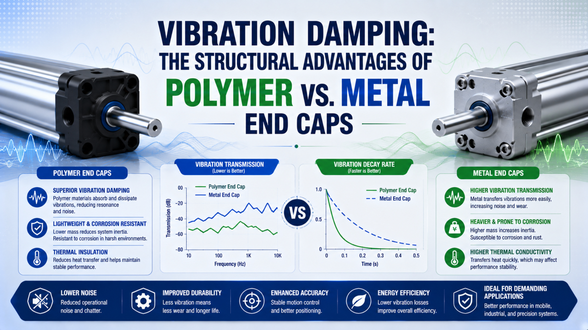
Polymer end caps can reduce structural ringing when their compound and geometry dissipate more energy than a metal design, but material damping alone does not prove lower machine noise, longer seal life, or greater structural strength. Compare complete cylinders under identical pressure, speed, load, cushioning, mounting, temperature, and measurement conditions.
A cylinder end cap does several jobs at once. It closes the pressure boundary, locates seals and barrel features, carries ports and cushioning passages, and may transfer mounting reactions into the machine. A material that damps vibration well still needs enough stiffness, dimensional stability, thread strength, chemical resistance, and fatigue margin for those duties.
Key Takeaways
- ASTM E756 measures loss factor and modulus.
- AVENTICS publishes a 10 bar polymer-cover mini-cylinder range.
- Parker’s metal-cover designs show why impact control belongs to the complete assembly: air cushioning, polyurethane washers, and plastic flow inserts manage separate functions.
- Compare released cylinders, never isolated material labels.
What Does Material Damping Actually Tell You?
ASTM E756 measures damping from 50 to 5,000 Hz and reports both loss factor and modulus, not a universal reduction percentage. Material behavior changes with temperature and frequency. Complete-cylinder response also depends on geometry, joints, excitation, and mounting (ASTM E756-05(2023), accessed 2026).
Material damping is the internal conversion of part of a cyclic mechanical input into heat; for a linear viscoelastic material, dynamic mechanical analysis separates that response into storage and loss components:
Here, is complex modulus, while $E'$ and $E''$ are the storage and loss moduli under the stated test conditions. Storage modulus captures recoverable response. Loss modulus describes the out-of-phase component associated with energy dissipation.
The loss tangent is:
The angle is the phase lag between applied cyclic stress and strain. A higher signals more damping only within those conditions. It cannot directly predict the acceleration, sound pressure, seal wear, or service life of an assembled pneumatic cylinder with different geometry and excitation.
ISO 6721-1 warns that results from different deformation modes are not automatically comparable. Tensile, shear, and flexural tests load a specimen differently, while a molded end cap also contains ribs, bosses, ports, inserts, seal grooves, and fastener seats (ISO 6721-1:2019, confirmed 2024).
A useful material comparison therefore needs two axes. Loss behavior indicates how much cyclic energy the material can dissipate, while modulus indicates how much the loaded part can deform. Selecting only the highest damping material can create a cover that moves too much at a seal, port, mounting face, or cushion bore.
Material Damping Is Not Structural Strength
BASF lists dry elastic-modulus ranges from 1,500 to 21,100 MPa across different polyamide families and reinforced grades. The same guide says temperature, moisture, storage, molding, glass-fiber content, fiber length, and orientation affect mechanical properties. “Engineering polymer” is therefore not a structural specification (BASF Ultramid guide, accessed 2026).
Metal end caps commonly offer high stiffness, stable machined datums, durable threads, and predictable mounting faces. A lightly damped metal structure can ring after impact, but that response can be controlled through geometry, joint stiffness, pneumatic cushioning, elastomeric stops, or an external shock absorber. Replacing metal with polymer is only one possible design action.
Reinforced polymers can combine useful stiffness with molded integration because ribs, port passages, sensor features, seal grooves, and insert pockets can be formed in one component. Mold flow also orients fibers, producing direction-dependent properties. Weld lines, gate location, wall transitions, voids, conditioning, and insert installation then become structural variables.
Long-term loading deserves separate treatment. A mounting screw, fitting, static seal, or pressurized wall can impose sustained stress even when the cylinder is not cycling. Polymers can creep or relax under that load. Temperature and absorbed moisture can change stiffness and dimensions. BASF reports that water absorption increases creep while decreasing strength, stiffness, and hardness in the cited polyamide family.
Metal has its own failure modes. Cast porosity, sharp section changes, damaged threads, corrosion, loose fasteners, and poor cushioning can still cause leakage, cracking, or noise. The end-cap strength and mounting guide covers those pressure-boundary and load-path checks in detail.
| Design issue | Polymer end-cap question | Metal end-cap question |
|---|---|---|
| Damping | Is loss behavior documented at service temperature and frequency? | Does the assembled structure ring at a damaging mode? |
| Stiffness | Will seal, port, and mounting datums stay within tolerance? | Does lower damping require a separate isolator or stop? |
| Sustained load | What creep and stress-relaxation data apply? | Can the joint loosen, fret, or fatigue? |
The interfaces then determine whether the selected material can be manufactured, assembled, and serviced consistently:
| Interface issue | Polymer end-cap question | Metal end-cap question |
|---|---|---|
| Threads and ports | Are molded threads or metal inserts qualified for torque and cycles? | Are thread engagement, wall thickness, and corrosion adequate? |
| Environment | How do heat, moisture, chemicals, UV, and cleaning affect the compound? | How do corrosion, coating damage, and galvanic pairs affect the part? |
| Manufacturing | Are fiber orientation, weld lines, voids, and conditioning controlled? | Are casting, machining, heat treatment, and coating controlled? |
Published Cylinder Designs Show Both Material Routes
AVENTICS uses high-quality polymer covers on its ICM mini-cylinder family. A cited 32 mm-bore configuration lists a 10 bar maximum working pressure, -20 to 70°C ambient range, and suitability for high-corrosion environments. Those are product-specific limits (AVENTICS ICM, accessed 2026).
The example establishes an important boundary. A polymer cover can be part of a commercially rated pneumatic cylinder when its compound, geometry, seals, interfaces, manufacturing process, and verification are engineered together. It does not establish a generic polymer pressure rating, vibration reduction, noise reduction, or cycle life.
Parker’s P1F ISO 15552 cylinder family provides a metal comparison. The catalog identifies aluminum end covers, 32 to 125 mm bores, and adjustable air cushioning (Parker P1F, accessed 2026). Those covers belong to a different cylinder architecture and cannot serve as a controlled material-only baseline.
The fair comparison is not “polymer versus aluminum” in isolation. It is one released cylinder configuration against another released configuration at the required pressure, temperature, speed, load, mounting, environment, and life target. A material coupon cannot validate a pressure boundary, and a cylinder catalog cannot reveal which material property caused a measured machine response.
| Published example | Cover material | Published boundary | What it demonstrates | What it does not demonstrate |
|---|---|---|---|---|
| AVENTICS ICM family | High-quality polymer | Product family up to 10 bar; cited 32 mm model at -20 to 70°C | Polymer covers can be engineered into a rated mini cylinder | Universal polymer damping, noise, strength, or life |
| Parker P1F family | Aluminum | 32-125 mm, adjustable air cushioning | Metal covers can support a broad ISO-cylinder architecture | Universal metal resonance, noise, or fatigue behavior |
For a broader component-level comparison, the aluminum alloy cylinder guide explains why barrel, end cap, piston, rod, seals, and fasteners should not be reduced to one whole-cylinder material label.
Does End-Cap Material Control End-of-Stroke Noise?
Parker states that its P1F air cushion absorbs kinetic energy from load and speed at both stroke ends. Another Parker design uses polyurethane end-of-stroke washers and plastic flow inserts inside metal end covers. These examples separate the stopping element from the structural cover material (Parker P1D, accessed 2026).
End-of-stroke sound can arrive through several paths:
- direct piston or carriage contact excites an internal stop;
- cushion pressure loads the cover;
- the cover, barrel, fasteners, mount, and frame respond as one connected structure;
- compressed air discharges through the valve and silencer;
- loose guards or tubing rattle;
- a lightly damped machine frame keeps vibrating after the piston stops, exciting adjacent guards, cable trays, panels, and mounting members with their own modes.
A better-damped end cap may reduce one structure-borne contribution. It cannot remove the incoming kinetic and pneumatic energy. It also cannot correct an exhaust restriction, a loose mount, excessive approach speed, insufficient cushion stroke, or an overloaded internal stop.
Start with energy and load path. The end-of-stroke energy guide explains why energy divided by stopping distance gives an average force, not the peak transmitted through the cylinder and machine. The pneumatic cushioning guide covers cushion adjustment and failure symptoms.
Airborne exhaust noise needs a different diagnosis. A cylinder cover cannot compensate for a noisy valve discharge or blocked silencer. Use the pneumatic silencer engineering guide when the dominant sound occurs at the valve exhaust rather than at the cylinder body.
| Observation | Likely path to check first | Useful measurement |
|---|---|---|
| Sharp pulse exactly at travel end | Piston impact, cushion, hard stop, mounting reaction | Velocity, chamber pressure, cap acceleration |
| Ringing continues after motion stops | Cylinder, bracket, guard, or frame mode | Acceleration waveform and frequency spectrum |
| Hiss or broadband sound at the valve | Exhaust flow, silencer, restriction | Sound level near exhaust plus back pressure |
| Rattle changes when a guard is held | Loose sheet, bracket, tubing, or fastener | Contact inspection and local acceleration |
| Position settles slowly without a loud impact | Compliance, friction, control, or guide behavior | Position, pressure, and time traces |
How Should You Compare Vibration and Noise Fairly?
ISO 11201 determines A-weighted machine emission sound pressure at defined positions and requires stated mounting and operating conditions. Its purpose includes comparing units under controlled environments. A phone reading at an arbitrary distance cannot establish that one end-cap material is 15 dB quieter (ISO 11201:2010, confirmed 2024).
Build the comparison around one controlled question. If the objective is to compare two end-cap materials, hold the remaining design and operating variables as close as possible. If the complete cylinders differ in bore, cushion, mass, geometry, or mounting, report the result as a product comparison rather than a material comparison.
Control these inputs:
- Cylinder and load: bore, stroke, rod or carriage, moving mass, orientation, guide, tooling, and stop location.
- Pneumatic conditions: dynamic supply pressure, both chamber pressures, valve, tubing, fittings, exhaust, and cushion setting.
- Motion: command timing, approach speed, acceleration, dwell, direction, and cycle rate.
- Installation: bracket, fastener torque, frame, load offset, hose strain, and sensor or guard attachments.
- Environment: temperature, polymer conditioning, humidity, background noise, and nearby operating equipment.
Measure at least one quantity for each relevant path, placing one accelerometer on the end cap and another on the mounting structure. Record piston or carriage position and velocity. When cushion behavior is part of the question, measure both chamber pressures near the cylinder and keep the microphone position, orientation, weighting, response setting, and background correction fixed.
NIOSH distinguishes sound level, time-weighted average, and dose, and recommends documenting instrument settings and operating conditions. Those occupational quantities answer different questions from a short end-of-stroke pulse (NIOSH noise measurement guidance, 2024). Report the actual metric, such as maximum A-weighted level, equivalent level over a defined cycle, C-weighted peak, or frequency-band result.
Repeat enough cycles to stabilize temperature, grease distribution, and polymer conditioning, and use multiple production parts when manufacturing variation matters. Preserve raw time histories, calibration records, part identification, and failure criteria. One quiet cycle is not a reliability test.
In our experience with replacement reviews, the most useful evidence is a synchronized record of position, both chamber pressures, end-cap acceleration, frame acceleration, and sound. It shows whether a loud event began with excessive approach speed, cushion pressure, structural ringing, or a separate exhaust pulse.
Which Material Fits the Application Boundary?
ISO 19973-3 expresses pneumatic-cylinder life in cycles or kilometres and defines test equipment and threshold levels for reliability assessment. It does not assign life from end-cap material alone. Any durability claim needs a released configuration, stated operating class, failure definition, sample plan, and test record (ISO 19973-3:2015, confirmed 2024).
A polymer end cap is a strong candidate when corrosion resistance, low mass, electrical isolation, molded feature integration, or local damping matters and the exact product is rated for the duty. It needs extra scrutiny where sustained mounting loads, high fitting torque, elevated temperature, moisture-driven dimensional change, aggressive chemicals, fire performance, or repeated disassembly dominate. That boundary is decisive.
A metal end cap is a strong candidate when high stiffness, stable datums, durable threaded interfaces, heat tolerance, and conventional mounting hardware matter. It needs extra scrutiny where impact ringing, corrosion, galvanic contact, installed mass, or complex machining drives the problem. Local elastomeric cushioning can provide better control than changing the complete cover material.
Material choice should follow the dominant failure path. If the issue is piston impact, reduce and absorb the incoming energy. If the issue is frame resonance, change the load path or modal response. If the issue is exhaust noise, treat the valve discharge. If the issue is creep at a port or mount, a higher-damping polymer may move the design in the wrong direction.
| Application priority | Polymer-cover candidate | Metal-cover candidate | Release evidence |
|---|---|---|---|
| Lower local ringing | Use when assembly testing confirms attenuation | Add cushion, isolator, geometry, or damping treatment if needed | Acceleration time trace and spectrum |
| High sustained mount load | Check creep, inserts, temperature, and deformation | Retains a stiff mounting datum when the model rating fits | Loaded dimensional and endurance test |
| Corrosive washdown | A compatible compound and hygienic geometry can suit the exposure | Stainless or protected metal can suit aggressive cleaning | Complete chemical and cleaning compatibility |
| Elevated temperature | Compound and every insert or seal set the limit | Use only within the configured catalog temperature | Exact configured temperature rating |
Service frequency and motion severity create a second group of selection checks:
| Service priority | Polymer-cover candidate | Metal-cover candidate | Release evidence |
|---|---|---|---|
| Frequent fitting service | Verify insert retention and allowable torque | Check published thread and torque-cycle limits | Torque-cycle and leak test |
| Low installed mass | Reduces cover mass in a qualified design | Aluminum balances mass and stiffness in many designs | Bill-of-material mass and parent-axis load |
| High impact energy | Damping alone is insufficient | Stiffness alone is insufficient | Cushion or shock-absorber energy capacity |
| Precision mounting | Verify creep, flatness, and thermal movement | Stable machined faces can preserve mounting datums | Alignment and loaded-position measurement |
What Should a Supplier or Replacement Review Confirm?
The published AVENTICS and Parker examples identify specific pressure, temperature, material, bore, and cushioning boundaries. Generic material labels omit that boundary. Ask for configured-cylinder evidence rather than a “polymer end cap” or “metal end cap” promise (AVENTICS ICM, accessed 2026).
Include these items in the technical package:
- Exact cylinder series, bore, stroke, function, rod or carriage type, and mounting.
- End-cap compound or alloy, grade or condition, reinforcement, and manufacturing process.
- Maximum and minimum pressure, proof or leakage test, temperature, and approved media.
- Cushion type, effective stroke, allowable energy or mass-speed envelope, and adjustment method.
- Moving mass, measured approach speed, cycle rate, direction, orientation, and external stop arrangement.
- Port and fastener materials, thread or insert design, permitted torque, and service-cycle limit.
- Static-seal geometry, allowed deformation, surface requirements, and assembly controls.
- Environmental exposure, including humidity, cleaners, oils, UV, corrosion, and particle contamination.
- Vibration and acoustic test method, sensor locations, frequency range, sound metric, background condition, and sample count.
- Reliability test class, failure threshold, cycles or distance, leakage trend, inspection findings, and raw-data availability.
For a replacement cylinder, record the installed symptom before removal. Note whether the sound comes from the cylinder, valve exhaust, guard, or frame. Photograph mounting witness marks and bracket gaps. Capture dynamic pressure, end-approach speed, cushion setting, payload, temperature, and the stroke direction that produces the problem.
Do not retrofit a different end cap because bolt holes or barrel dimensions appear to match. Seal squeeze, fastener preload, cushion passages, bearing alignment, port threads, and proof-test requirements can still change the pressure boundary. Use the contact page for a configuration review.
The About Us page identifies the engineering and manufacturing scope behind that review.
Polymer vs. Metal End Caps FAQs
ISO 6721 separates storage and loss behavior, while ISO 19973-3 treats cylinder reliability through controlled testing and defined thresholds. Together they support five practical answers: material damping is measurable, but product noise, pressure integrity, retrofit compatibility, and life still require configuration-specific evidence (ISO 6721-1, confirmed 2024).
Are polymer end caps always quieter than metal end caps?
No. Polymers often provide more material damping, but machine sound also depends on piston impact, cushioning, exhaust flow, cover geometry, mounting stiffness, guards, and structural modes. Compare complete cylinders with identical motion and installation conditions. Report the microphone position and sound metric instead of assigning one universal decibel reduction.
Can polymer end caps handle industrial pneumatic pressure?
Yes, for a rated design. AVENTICS lists polymer covers on its ICM family and a 10 bar maximum for the cited range. That product example cannot be transferred to another compound, wall section, insert, seal, port, temperature, or manufacturing process.
Can I retrofit a polymer end cap onto a metal-cover cylinder?
Only with manufacturer-approved compatibility evidence. Matching the outside shape or fastener pattern does not establish barrel retention, static-seal compression, cushion alignment, port strength, bearing location, or proof pressure. Treat the end cap as part of the pressure boundary and rebuild only with an approved drawing, procedure, and test.
Does glass-fiber reinforcement improve every end-cap property?
No. Glass fiber can raise stiffness and strength in selected directions, but content, length, orientation, weld lines, temperature, moisture, and molding conditions affect the result. Reinforcement can also change impact behavior and dimensional anisotropy. Use compound-specific data and finished-part tests rather than an unqualified “glass-filled nylon” label.
How should cylinder life be compared between end-cap materials?
State the cylinder configuration, sample count, pressure, speed, load, temperature, environment, lubrication, mounting, cushioning, failure threshold, and test duration in cycles or kilometres. Track leakage, deformation, cracks, insert movement, fastener condition, and performance drift. Without those conditions, a cycle-life comparison cannot support a purchasing decision.
Sources and technical references
-
ASTM International. ASTM E756-05(2023), Standard Test Method for Measuring Vibration-Damping Properties of Materials. Active edition 2023. Retrieved July 23, 2026.
-
International Organization for Standardization. ISO 6721-1:2019, Plastics - Determination of dynamic mechanical properties - General principles. Confirmed 2024. Retrieved July 23, 2026.
-
BASF. Ultramid polyamide product and engineering guide. Retrieved July 23, 2026.
-
Emerson AVENTICS. Series ICM mini cylinders with high-quality polymer covers. Retrieved July 23, 2026.
-
Parker Hannifin. P1F ISO 15552 pneumatic cylinder technical catalog. Retrieved July 23, 2026.
-
Parker Hannifin. P1D Series pneumatic cylinder catalog. Retrieved July 23, 2026.
-
International Organization for Standardization. ISO 11201:2010, Machinery emission sound-pressure measurement. Confirmed 2024. Retrieved July 23, 2026.
-
National Institute for Occupational Safety and Health. Understand Noise Exposure. Updated 2024. Retrieved July 23, 2026.
-
International Organization for Standardization. ISO 19973-3:2015, Reliability testing for pneumatic cylinders with piston rods. Confirmed 2024. Retrieved July 23, 2026.