

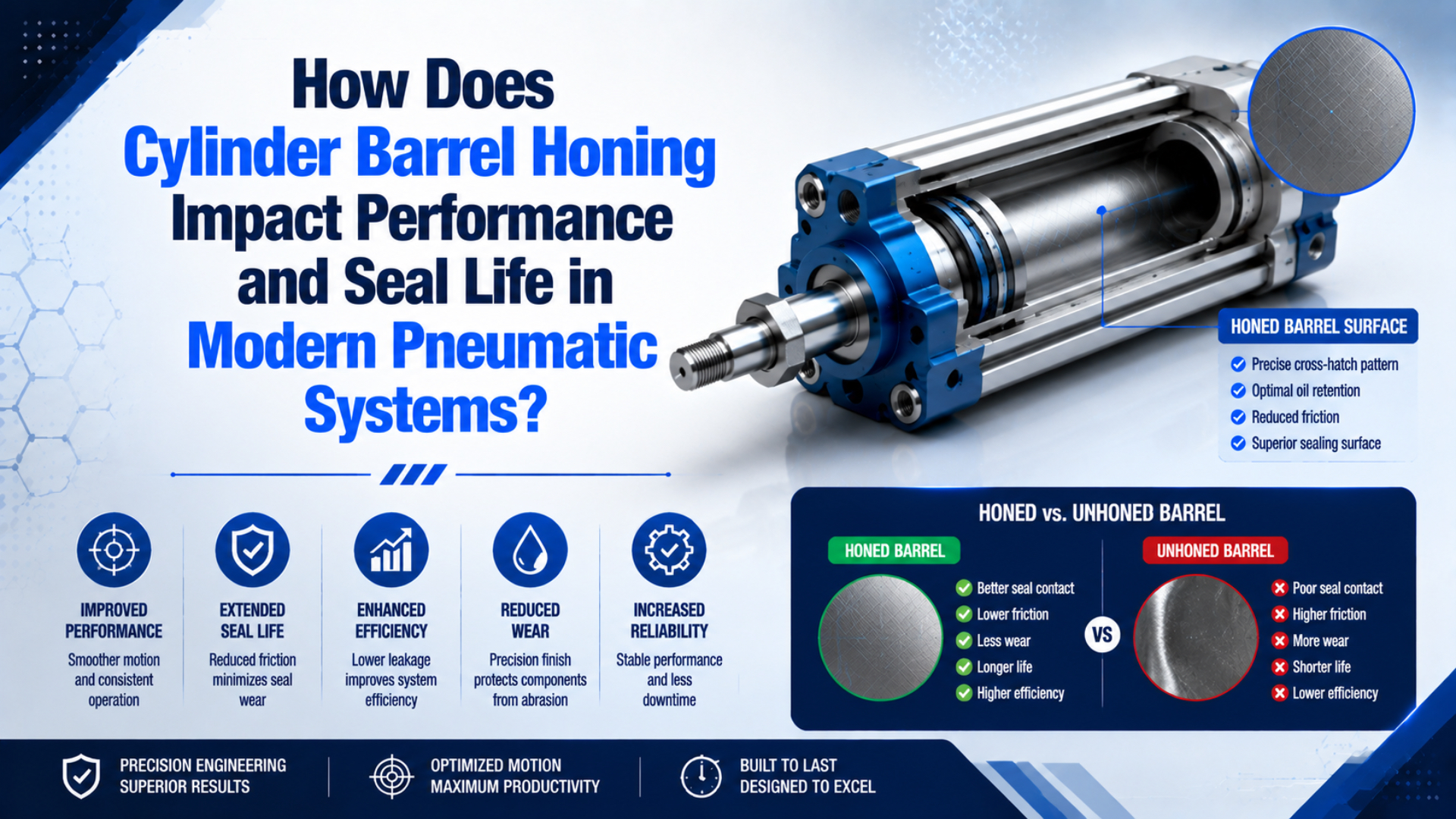
Cylinder barrel honing is a controlled abrasive process that affects pneumatic performance by setting bore size, geometry, texture, and the surface supporting the piston seal. A suitable finish can reduce avoidable abrasion, preserve the intended lubricant film, and support repeatable breakaway behavior. An unsuitable finish can cut a new seal, create a leakage path, or leave the bore outside its dimensional tolerance.
There isn’t one universal honing number for every pneumatic cylinder. Parker’s pneumatic seal guidance gives dynamic surface examples of Ra 0.2 µm / Rz 1.0 µm for rubber and PTFE products and Ra 0.4 µm / Rz 1.6 µm for polyurethane products (Parker Pneumatic Seals, accessed 2026). The seal profile, compound, lubricant, barrel material, pressure, speed, and duty cycle must be reviewed together.
This article covers post-honing acceptance. For tube and RFQ context, see our honed cylinder tube guide.
Key Takeaways
- Parker lists different dynamic finish examples for rubber/PTFE and polyurethane seals, so
Racannot be copied without identifying the seal.- ISO 21920 requires surface texture to be defined with a measurement specification, not a roughness number alone.
- Accept the barrel only after checking texture, bore size, geometry, cleanliness, coating condition, and seal compatibility.
What Does Honing Change at the Pneumatic Seal Interface?
Honing uses rotating and reciprocating abrasive stones to remove material from a bore while improving its geometry and surface finish. Sunnen describes the process as a way to control bore diameter, roundness, straightness, and texture rather than simply make the surface look polished (Sunnen Honing Processes, accessed 2026).
Every stroke brings the piston seal across the finished bore. A useful surface has enough supporting area to carry the seal, limited peaks that won’t abrade its lip, and valleys compatible with the intended lubricant film. Long axial scratches are especially serious because they can form direct leakage paths between chambers.
A shiny bore is not proof.
Honing can also correct some pre-existing geometry errors. A controlled process may reduce taper, barrel shape, hourglass shape, local tight spots, and out-of-round conditions. It can’t guarantee success if the tube is bent, deeply scored, cracked, too thin, or already close to its maximum allowable bore diameter.
Results depend on the starting bore, abrasive, pressure, stroke speed, rotational speed, coolant, stock allowance, and inspection feedback. A crosshatch may be visible, but appearance alone doesn’t prove that the finished bore meets the seal or dimensional specification.
Ra Is Only One Part of a Functional Bore Specification
Current profile-surface practice uses ISO 21920-2:2021 for terms and parameters and ISO 21920-3:2021 for the specification operator that determines compliance. ISO lists ISO 4287 and ISO 4288 as withdrawn predecessors, so a current drawing should identify the governing standard and measurement rules (ISO 21920-2; ISO 21920-3).
Ra is the arithmetic mean height of the roughness profile. Two bores can have the same Ra and still behave differently because one has sharp isolated peaks, another has deep valleys, and a third contains directional scratches or excessive waviness. Instrument choice, filter, cutoff, evaluation length, and trace direction also change the reported result. ASME B46.1-2019 (R2026) makes that measurement issue visible: filter settings separate roughness from waviness and can change the reported Ra. Writing only “Ra 0.4 µm” on a purchase order leaves the inspection method underdefined.
Measure before you polish.
Use a parameter set that describes the function you need:
| Parameter or condition | What it reveals | Why the seal cares |
|---|---|---|
Ra |
Average profile height | Useful screening value, but incomplete alone |
Rz |
Peak-to-valley behavior over sampling lengths | Helps expose peaks and valleys hidden by an average |
Rmax or equivalent maximum-height control |
Worst local profile feature | Can catch an isolated defect that damages a seal |
| Material ratio | Supporting plateau area at a stated depth | Relates supporting surface to lubricant-retaining valleys |
| Lay and crosshatch direction | Direction of machining marks | Axial marks can become leakage paths |
| Waviness and form | Longer-wavelength variation | Can change local seal squeeze and friction |
| Visual defect limit | Scratches, chatter, tears, embedded debris | Some damaging defects aren’t represented well by one trace |
The acceptance question isn’t “How smooth is the bore?” It is “Does the measured surface support this seal under this duty cycle without hiding a leakage path or geometry error?” That wording prevents the common mistake of polishing toward the lowest possible Ra while ignoring lubricant retention and bore form.
Which Surface-Finish Limits Should You Put on the Drawing?
Parker’s pneumatic catalogue separates dynamic surfaces by seal material: rubber and PTFE examples use Rz 1.0 µm / Ra 0.2 µm with an 80-95% stated material-ratio range, while polyurethane uses Rz 1.6 µm / Ra 0.4 µm with a 60-80% range. These are supplier examples, not universal substitutes for a seal drawing.
Begin with the exact seal manufacturer’s counter-surface requirement. Record the seal profile and compound, not just a generic label such as NBR, PU, or PTFE. Profile geometry, energization, fillers, hardness, and lubrication features can change what the moving surface requires. SKF’s hydraulic seal guidance provides another useful parameter package for honed or roller-burnished dynamic cylinder bores: Ra 0.05-0.2 µm, Rz 0.4-2 µm, Rmax 0.4-2.5 µm, and Rmr 50-95% at a stated cutting depth (SKF Hydraulic Seals, 2024). Those values show why multiple parameters matter, but they shouldn’t be copied into a pneumatic drawing without checking the selected seal and lubricant regime.
A build-ready barrel specification should identify:
- Finished bore diameter and tolerance. State the temperature basis and whether the limit applies before or after coating.
- Form limits. Define roundness, cylindricity, straightness, taper, or a supplier-approved alternative over the working length.
- Surface parameters. Give the required Ra and supporting parameters, plus the applicable ISO or ASME measurement convention.
- Measurement setup. State trace direction, cutoff, evaluation length, instrument type, and locations along the bore.
- Visual acceptance. Prohibit axial scoring, chatter, torn material, embedded abrasive, corrosion, coating breakthrough, and burrs at ports or grooves.
- Seal and lubricant context. Name the seal drawing, compound, approved assembly grease, and whether external air-line lubrication is permitted.
- Cleaning and preservation. Require removal of abrasive residue and protection against corrosion or handling damage after inspection.
If a supplier can’t identify the seal requirement behind a roughness limit, pause the release. Our dynamic versus static cylinder seal guide explains why a moving piston interface needs different evidence from an end-cap O-ring groove.
Post-Honing Inspection: Geometry, Texture, and Cleanliness
Sunnen treats honing as both sizing and finishing, and its technical material describes correcting bore geometry while producing the required surface. That means inspection must cover the whole working length. One roughness trace near the open end cannot prove that diameter, taper, crosshatch, or texture remains acceptable at mid-stroke and the far end (Sunnen Educational Information, accessed 2026).
Keep form vocabulary precise. Taper, bellmouth, barrel shape, hourglass shape, lobing, triangularity, straightness, roundness, cylindricity, coaxiality, and runout are not interchangeable defects.
Depending on the drawing, the inspection system may combine a contact-stylus profilometer, air gauge, dial bore gauge, roundness machine, coordinate measuring machine, calibrated master, and borescope. Each instrument resolves a different feature, so its capability, uncertainty, access, fixturing, and datum strategy must suit the tolerance being accepted.
Use an inspection sequence that preserves evidence:
- Review the drawing and repair allowance first. Confirm the final allowable diameter, coating thickness, seal compatibility, and material removal limit before touching the bore.
- Check the uncleaned failure pattern. Photograph scoring, polished bands, corrosion, embedded particles, and one-sided wear. Mark the installed orientation when side load is suspected.
- Measure diameter at several stations and directions. Include both ends and mid-stroke. A single bore-gauge reading can miss taper or lobing.
- Evaluate form over the working length. Use equipment capable of proving the drawing’s roundness, straightness, or cylindricity requirement. Don’t substitute a visual crosshatch check.
- Measure texture under the specified setup. Record the instrument, filter, cutoff, evaluation length, trace direction, values, locations, and calibration status.
- Inspect edges and interruptions. Ports, grooves, cushion features, and lead-in chamfers must not cut the seal during assembly or operation.
- Clean, dry, and reinspect. Residual abrasive can turn a dimensionally correct barrel into a seal-wear source during the first cycles.
- Run a controlled acceptance test. Check leakage, smooth travel, breakaway behavior, cushioning, and temperature under declared pressure, load, speed, and lubrication conditions.
In our experience, the most useful report isn’t a single Ra reading. It is a location map that pairs bore diameter and texture readings with visual defect notes. That map makes end-to-end variation visible and gives the seal supplier something concrete to review when a result falls near the limit.
Crosshatch is evidence, not acceptance.
Don’t tune away a mechanical problem with higher air pressure. If the cylinder jumps at the start of stroke, compare the bore and seal evidence with the pneumatic cylinder breakaway-force guide. One-sided polishing should also trigger checks of mounting, guidance, and side load rather than another honing pass.
When Is Re-Honing More Risky Than Replacing the Barrel?
Re-honing removes material, so the final diameter and remaining surface system decide whether repair is viable. Parker’s published pneumatic finish examples differ by seal family, and Sunnen describes honing as a stock-removal process. Neither source supports unlimited correction of scratches, taper, coating loss, or an already oversized bore.
Replacement is usually the safer path when:
- cleanup would oversize the seal track;
- anodizing, plating, hard coating, or another engineered layer would be removed below its minimum thickness;
- corrosion pits or axial scoring remain deeper than the permitted cleanup allowance;
- the tube is bent or cracked;
- repeated honing has left no traceable baseline for wall thickness or bore size;
- replacement seals are unavailable for the proposed finished diameter, or using a nonstandard seal would leave the repair without a controlled groove, squeeze, material, and future spare-parts path;
- repair cost approaches a new barrel or cylinder without restoring traceability.
Aluminum profile cylinders deserve special caution. The seal may run on an anodized or otherwise treated bore rather than bare aluminum. Removing that layer can change hardness, corrosion behavior, friction, and seal compatibility even when the measured Ra looks acceptable. Steel and stainless barrels also need material-specific planning. Stone selection, coolant, stock allowance, heat control, corrosion protection, and cleaning practice affect the result. Copying an engine-cylinder crosshatch recipe into a pneumatic repair specification isn’t a defensible method.
Material removal is irreversible.
Use the repair-versus-replace decision framework when the damage extends beyond the seal track. A worn guide, loose piston, misaligned mount, or damaged end cap can ruin a newly honed barrel and seal kit.
How Does Bore Condition Affect Seal Life in Service?
Pneumatic cylinder reliability is reported by ISO 19973-3 in cycles or kilometres under declared test conditions. The standard does not assign a universal service life to a surface finish. A credible comparison states the cylinder, seal, pressure, stroke, speed, load, temperature, air quality, lubrication, sample size, and failure threshold (ISO 19973-3, confirmed 2021).
Surface condition changes several failure mechanisms:
| Bore condition | Likely mechanism | Field evidence | Next check |
|---|---|---|---|
| Excessive peaks | Abrasive lip wear | Roughened or cut seal surface | Texture parameters and cleaning |
| Axial scratch | Chamber-to-chamber leakage path | Internal bypass after a seal change | Bore inspection along the stroke |
| Low supporting area | Local contact stress and unstable film | Wear concentrated on small regions | Material-ratio parameter and seal guidance |
| Too little useful texture | Weak lubricant retention | Stick-slip or rising breakaway force | Lubrication policy and supplier limit |
| Taper or ovality | Uneven seal squeeze | Intermittent leakage or one-sided wear | Multi-station bore measurement |
| Embedded abrasive or dirt | Three-body abrasion | Rapid repeat failure after repair | Cleaning, filtration, and assembly controls |
| Side-loaded piston | Uneven contact unrelated to honing alone | Matching wear on seal and guide | Mounting, bearing, rod, and load path |
Bore texture is only one part of the tribological system. Added air-line lubricant can change seal behavior, and stopping it after long use may remove a film the system has come to depend on. Check the air lubrication and seal material guide before changing plant policy.
If a new piston seal leaks soon after installation, don’t assume that honing was the only cause. Verify seal orientation, groove damage, piston guidance, contamination, connected valve leakage, and assembly cuts. The internal cylinder leakage guide provides a controlled diagnostic sequence.
Evidence for Seal-Life and Performance Claims
Reliability testing under ISO 19973-3 evaluates first failure under defined pneumatic cylinder conditions and recognizes both cycles and kilometres as lifetime measures. Statements such as “three times longer life” or “30 months without leakage” are incomplete unless the tested configurations, duty conditions, sample count, measurement method, and failure criteria are disclosed.
Ask for evidence in three layers:
- Drawing evidence: the approved bore, coating, and seal requirements.
- Inspection evidence: location-based dimensional and texture results, visual records, instrument configuration, calibration status, measurement uncertainty, ambient conditions, datum setup, and cleaning confirmation.
- Performance evidence: measured leakage, breakaway and running behavior, stroke consistency, temperature, wear, and test duration under declared pressure, load, speed, environment, and lubrication conditions.
Field history is useful when it is configuration-specific. Record the cylinder series, bore, stroke, pressure, speed, cycle rate, load, mounting, air quality, lubricant, seal batch, maintenance actions, and observed failure mode. A plant-wide average that mixes different machines cannot prove that one honing finish caused the outcome. Treat a surface-finish certificate as one line of evidence, not a warranty of seal life. The most defensible acceptance links the drawing to measured barrel results, then links those results to a controlled leak and motion test. That chain is much stronger than a supplier adjective such as “precision honed.”
Cylinder Barrel Honing FAQs
Parker publishes at least two different dynamic surface examples: Ra 0.2 µm for rubber/PTFE products and Ra 0.4 µm for polyurethane. These FAQs explain why seal identity, measurement settings, bore geometry, repair allowance, and test conditions must be settled before approving a honed pneumatic barrel.
Is a lower Ra always better for pneumatic cylinder seals?
No. A lower Ra does not reveal peak shape, valleys, lay, waviness, or material ratio. It can also conflict with the selected seal’s lubricant-retention needs. Use the exact seal manufacturer’s counter-surface requirement and specify the measurement method. A very shiny bore can still leak, stick, or wear unevenly.
What crosshatch angle should a pneumatic cylinder barrel have?
There is no universal angle that can be applied to every pneumatic barrel. The acceptable pattern depends on the honing process, material, seal, lubricant, speed, and supplier drawing. Specify the functional surface parameters and inspection method first. Treat crosshatch appearance as supporting evidence, not a substitute for measured texture and geometry.
Can a scratched aluminum cylinder barrel be re-honed?
Only after confirming the scratch depth, finished-diameter allowance, wall condition, coating or anodizing thickness, and availability of a compatible seal for the final bore. If cleanup removes an engineered surface or exceeds the allowable diameter, replacing the barrel is safer than accepting a visually smooth but functionally altered bore.
Which measurements belong on a honing inspection report?
Record bore diameter at several axial stations and directions, the required form measurements, Ra plus supporting texture parameters, trace direction, cutoff, evaluation length, instrument and calibration status, visual defects, coating condition, and cleaning result. The report should identify the exact drawing revision, seal, barrel, and measurement locations.
How can a supplier prove that honing extended seal life?
Proof requires a controlled comparison with declared cylinder, seal, pressure, stroke, speed, load, temperature, air quality, lubrication, sample quantity, inspection intervals, and failure criteria. ISO 19973-3 provides a reliability-test framework. Anonymous anecdotes or a months-in-service comparison without matched duty conditions do not establish causation.