

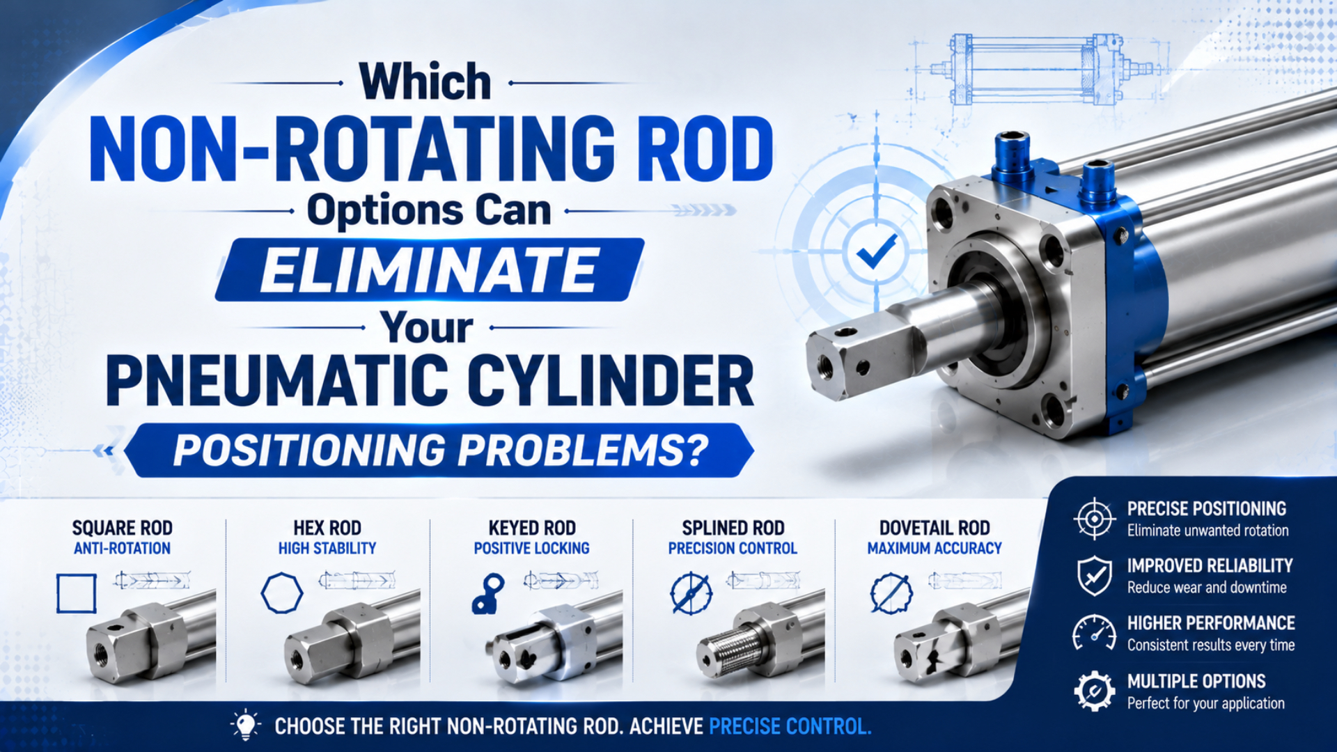
Non-rotating rod options should be compared by guide mechanism, angular play, allowable moment, stroke, and speed. An anti-twist pin or profiled rod can hold tool orientation under a light centered load. Dual-rod and guided cylinders add a wider mechanical constraint for offset tooling and transverse loads. A separately guided slide is usually the safer architecture when the load creates substantial moment.
Do not select from a universal claim such as “rotation-free” or “100% anti-rotation.” SMC, Festo, and Parker publish performance for specific constructions and test conditions. The installed tool can still move because of guide clearance, rod deflection, mounting compliance, loose fasteners, or an unsupported overhang.
Key Takeaways
- SMC attributes ±0.1° non-rotating accuracy to the dual-rod construction of its CXS2 series.
- Anti-twist protection controls angular orientation; a rod lock controls axial movement.
- Calculate offset moment before comparing catalog load and moment limits.
- Magnetic coupling and position sensing do not mechanically guide a load.
The best starting question isn’t “Which rod shape prevents rotation?” It is “Where should the machine react the load moment?” If the answer is a small guide inside the cylinder, a compact anti-twist option may work. If the answer is a pair of external bearings or guide rods, choose an actuator designed around that load path.
What Positioning Problem Are You Actually Trying to Remove?
A non-rotating solution should be chosen by the unwanted degree of freedom and the load acting on it. SMC lists ±0.1° non-rotating accuracy for its CXS2 dual-rod cylinder, while Festo describes a separate anti-twist option that prevents rod turning and an additional piston guide that absorbs higher transverse loads (SMC CXS2; Festo DPCA, accessed July 19, 2026).
Start by naming the error at the process datum:
| Observed problem | Mechanical question | Function normally required |
|---|---|---|
| Tool turns around the cylinder axis | Is angular clearance or guide twist moving the tool? | Anti-rotation constraint |
| Tool shifts sideways under an offset load | Where are transverse force and bending moment reacted? | Guide rods, slide bearings, or external linear guide |
| Rod drifts axially after stopping | Is trapped air leaking or compressing? | Motion control plus a suitable rod lock or brake |
| Sensor repeats but the part does not | Is the sensor upstream of a loose or flexible interface? | Output-side measurement and mechanical correction |
| Carriage pitches or yaws | Does the guide have enough spacing and moment capacity? | Guided slide selected for the relevant moment axes |
Non-rotating accuracy is the permitted angular orientation change around the actuator’s travel axis under the manufacturer’s stated conditions. It isn’t the same as linear position accuracy, repeatability, straightness, or resistance to side load. One cylinder can perform well in one category and poorly in another.
Likewise, a keyed or flattened piston rod is not automatically a linear bearing. Its anti-twist surfaces may resist limited torque, but the cylinder’s rod bushing can still be overloaded by a transverse force. If the tooling creates a moment, determine whether the catalog explicitly allows that load or requires an external guide.
Non-Rotating Rod Options and Their Mechanical Constraints
Current catalog designs use several distinct constraints. Parker’s 2MNR uses three hard-chrome-plated piston rods and a tooling plate, while SMC’s CXS2 uses a dual-piston, dual-rod construction and states ±0.1° non-rotating accuracy. Those architectures control orientation through rod spacing rather than an unsupported promise of zero clearance (Parker 2MNR; SMC CXS2, accessed July 19, 2026).
The practical choices are:
- Anti-twist pin or internal guide: A guide pin runs in a matching feature inside a compact cylinder. It preserves a familiar single-rod package and works best when the catalog permits the applied torque and transverse load.
- Profiled piston rod: A flat, keyed, polygonal, or otherwise shaped rod runs through a matching bushing. Availability and load capacity are manufacturer-specific. Clearance, sealing, wear, and contamination exposure still matter.
- Dual-rod or multiple-rod cylinder: Two or more rods create a wider constraint. A shared plate keeps the output orientation and can provide a convenient tooling face.
- Integrated guide cylinder or guided slide: Separate guide rods, bushings, or recirculating bearings carry side forces and moments while the pneumatic piston supplies thrust.
- Standard cylinder plus external linear guide: A floating joint lets the cylinder drive a separately supported carriage. This is often the clearest load path for long strokes, large moments, or an existing machine guide.
- Rodless actuator with guided carriage: Removing the protruding piston rod saves length, but the carriage still needs a guide when it carries pitch, yaw, or roll moments.
From our analysis of these catalog architectures, “non-rotating rod” is better treated as a result than a product family. Several mechanisms can deliver the result, but they route torque and side load through different bearings. The correct architecture becomes clearer once the force path is drawn from the tool back to the machine frame.
Compact Anti-Twist Pins and Profiled Rods
Festo offers its DPCA compact-cylinder anti-twist option across piston diameters from 1/2 to 4 inches, but it describes the anti-twist feature separately from the additional piston guide used for higher transverse loads. That distinction makes the compact option most defensible when angular torque is limited and the external load remains well supported (Festo DPCA, 2023).
Choose this architecture when all of the following are true:
- The primary problem is tool orientation around the rod axis.
- The payload is centered or supported by another structure.
- Applied torque and transverse force remain within the exact option’s ratings.
- Stroke and speed fall inside the catalog range.
- Some catalog-stated torsional clearance is acceptable.
- Dirt, washdown, lubricant, and temperature suit the guide surfaces and seals.
This solution can be attractive for a compact stopper, pin insertion tool, nozzle, marking head, or orientation-sensitive pusher. It keeps the package close to a standard cylinder and may simplify mounting. The tradeoff is that a small internal constraint has less bearing spacing than a broad external guide.
Do not bolt a long arm directly to the rod and assume the anti-twist feature will carry the resulting moment. A small transverse force becomes a large moment when the tool center is far from the guide. Wear can also increase angular clearance over time, so acceptance criteria should include the installed tool angle after representative cycling, not only a new-cylinder catalog value.
When Should You Choose a Dual-Rod or Guided Cylinder?
SMC’s MGG guide-cylinder catalog gives unloaded, retracted non-rotating guideline values from approximately ±0.07° to ±0.02°, depending on bore and bearing arrangement. The same document warns that these values exclude payload and guide-rod deflection. A precise catalog angle therefore doesn’t remove the need to calculate the installed load (SMC MGG, accessed July 19, 2026).
A dual-rod cylinder is useful when the shared plate needs to stay oriented and the load is moderate. An integrated guided cylinder goes further by providing dedicated guide rods and selectable bearing types. SMC describes slide bearings as suitable for wear resistance and heavy-load capacity, while ball bushings emphasize smooth movement and precision. The correct choice still comes from the series load charts.
Use a guided slide when the application includes:
- An offset gripper, clamp, stop, pusher, or tooling plate
- Repeated transverse force during contact with a part
- Pitch, yaw, or roll moment at the moving plate
- A requirement to mount the work directly on a guided output
- A need to control deflection as well as angular rotation
- A short or medium stroke where an integrated package saves assembly space
For a long stroke or an existing machine rail, a standard cylinder connected to the carriage with a floating joint may be more forgiving. The guide establishes the motion datum. The cylinder contributes thrust without being forced to act as a second, slightly misaligned guide. See How to Mitigate Side Load Issues in Linear Cylinder Applications for the alignment boundary.
How Do Side Load, Offset, and Moment Change the Selection?
One Festo DFM-25-20 guided drive lists 29.35 N·m maximum torque about one axis and 12.52 N·m about each of the other two, while its permissible torque as a function of stroke is lower. The example shows why “allowable moment” must include the axis, stroke, bearing, and load case (Festo DFM-25-20, accessed July 19, 2026).
For a force acting at a perpendicular offset, the first-pass moment is:
Applied moment is the turning effect created when a force acts away from the guide datum. It is a load demand, not the actuator’s allowable capacity.
where is the applied moment in newton-metres, is the transverse or process force in newtons, and is the perpendicular distance from the relevant guide datum to the force line in metres. Use the actual center of gravity and tool-contact point, not the face of the mounting plate.
Suppose a 60 N tool and process load acts 0.12 m from the guide datum:
That 7.2 N·m result is only one load component. Acceleration can increase the effective force, and a tool may create moments about more than one axis. Apply the selected manufacturer’s combined-load method when several forces or moments act together. Do not add unlike axis limits into an invented universal capacity number.
Also check deflection. A guide may remain below its structural load limit while deflecting too far for the process tolerance. Longer strokes, larger overhang, higher acceleration, weaker mounting surfaces, and worn bearings can all move the tool. Parker’s guided-cylinder data plots side load against stroke plus offset distance and shows a different deflection curve for each configuration (Parker HB guided cylinders, accessed July 19, 2026).
If cylinder thrust is still unknown, estimate it first with the Cylinder Force Calculator. Then calculate the offset moment separately and compare force, moment, deflection, kinetic energy, and speed against the exact actuator catalog.
Do Sensors, Rod Locks, or Magnetic Couplings Stop Rotation?
No. SMC lists 0.1 mm repeatability for its D-MP actuator position sensor, but that value describes sensing, not a mechanical angular constraint. A sensor can reveal a position while a rod lock holds axial motion and a guide reacts rotation. Each function needs its own component and acceptance test (SMC actuator position sensor, accessed July 19, 2026).
A rod lock is an axial holding or braking device used under its published engagement and load conditions. It does not provide continuous angular guidance along the cylinder stroke.
Keep the functions separate:
| Component | What it does | What it does not establish |
|---|---|---|
| Auto switch or position sensor | Detects piston or carriage position | Tool orientation, side-load capacity, or mechanical holding |
| Rod lock or clamping unit | Resists axial rod movement under stated conditions | Angular guidance or accurate positioning by itself |
| Magnetic coupling | Transfers axial force through the cylinder wall | Carrier rotation control or external moment capacity |
| Flow control | Changes cylinder speed by restricting airflow | Positive angular constraint |
| External stop | Establishes an endpoint datum | Guidance throughout the stroke |
| Linear guide | Constrains transverse and angular motion | Pneumatic thrust or safe load holding after air loss |
A magnetically coupled rodless actuator can still be an excellent choice for compact long-stroke motion. Its carriage needs an integral or external guide if the load applies roll, pitch, or yaw moment. Read How Does a Magnetic Rodless Cylinder Work? for the coupling mechanism, then use the guide’s moment charts for the load decision.
Similarly, a rod lock can stabilize a stopped axis without preventing the tool from twisting. The Pneumatic Rod Lock Units guide separates static holding from dynamic braking and safety duties.
What Data Should Drive the Final Non-Rotating Cylinder Choice?
SMC’s CXS2 listing combines ±0.1° non-rotating accuracy with a maximum piston speed of 800 mm/s and allowable kinetic energy of 0.016 J. Those are separate limits for one product family. A valid selection must pass every relevant limit rather than treating the angle value as a complete specification (SMC CXS2, accessed July 19, 2026).
Build the request around measurable inputs:
- Required stroke, extend and retract time, dwell time, and cycles per minute
- Supply pressure available at the cylinder while air is flowing
- Payload mass, tooling mass, and moving plate mass
- Center-of-gravity coordinates relative to the guide or plate datum
- Process forces and the points where they act
- Required angular orientation, linear repeatability, and allowable deflection
- Mounting orientation and gravity direction
- External guide arrangement, if one already exists
- Bearing preference, contamination, washdown, temperature, and lubrication limits
- End-impact, cushion, shock-absorber, and air-loss behavior
Then compare candidate catalogs in a common table:
| Selection item | Evidence to request | Common mistake |
|---|---|---|
| Non-rotating accuracy or torsional backlash | Exact model, load state, stroke position, and test condition | Applying one bore’s unloaded value to every size |
| Allowable force and moments | Axis-specific dynamic and static limits | Comparing only payload mass |
| Deflection | Curve at actual stroke and overhang | Assuming “within load limit” means accurate enough |
| Speed and impact | Piston-speed, kinetic-energy, cushion, and stop limits | Slowing the cylinder only after hardware is selected |
| Bearing and guide | Plain, slide, ball-bushing, or recirculating guide data | Choosing “precision” without checking contamination and duty |
| Mounting | Dowel datums, bolt pattern, flatness, and plate stiffness | Letting mounting compliance dominate the guide |
| Service | Lubrication, wear inspection, seals, guide parts, and adjustment | Calling any mechanism maintenance-free |
A useful acceptance specification puts the angle and load in the same sentence: “The tool shall remain within the stated angular window at the process datum under the maximum defined offset load, at both stroke ends, after warm-up.” That wording exposes whether the catalog figure and the machine requirement describe the same condition.
How Can Installation Avoid Binding and Lost Accuracy?
Parker’s HB guided-cylinder load charts are based on dynamic conditions corresponding to a 10-million-cycle bearing life; Parker notes that higher dynamic loads reduce life and that acceleration, velocity, vibration, and orientation can change the result. Installation must therefore preserve the load assumptions used during selection (Parker HB, accessed July 19, 2026).
Use one clear motion datum. If a guided cylinder drives a separate machine rail, rigidly locating both guides can create a closed tolerance loop and binding. A floating joint or compliant connection should accommodate the permitted offset without consuming stroke or allowing unwanted tool rotation.
During assembly:
- Clean and inspect the mounting faces.
- Use dowels only where the product drawing defines datum holes.
- Tighten fasteners in the specified sequence and torque range.
- Move the axis through the complete stroke at low speed before attaching the full process load.
- Confirm that the coupling remains centered and free to articulate.
- Measure tool angle and lateral position at both stroke ends and at the process point.
- Repeat the measurement under the lightest and heaviest operating loads.
- Inspect guide clearance, lubrication, seals, fasteners, and impact devices at documented intervals.
Do not use a cylinder rod, guide rod, or tooling plate as a convenient handle during installation. A small bend or impact can produce tight spots that are invisible at one stroke position. If the tool orientation changes only under load, measure plate and bracket deflection before blaming internal cylinder clearance.
For position feedback, place the measurement datum as close as practical to the process output. The Pneumatic Cylinder Position Sensing guide explains what common magnetic switches and continuous sensors can detect. The sensor verifies motion; it doesn’t repair the mechanical load path.
Non-Rotating Pneumatic Cylinder FAQs
SMC’s guided-cylinder comparison states that load capability changes with operating speed and overhang, while its CXS2 assigns ±0.1° to a particular dual-rod architecture. The answers below therefore avoid universal angle or payload promises and keep each decision tied to the selected model’s conditions (SMC guided-cylinder selection, accessed July 19, 2026).
Does a dual-rod cylinder always prevent rotation completely?
No. Two rods provide a strong angular constraint, but bearings and fits still have clearance and can deflect under load. Use the manufacturer’s non-rotating accuracy for the exact bore and bearing type, then verify the installed tool under its actual offset load. “Dual rod” describes the architecture, not zero angular movement.
Is a rod lock the same as an anti-rotation device?
No. A rod lock resists axial movement when engaged, subject to its holding or braking rating. An anti-rotation device constrains angular movement around the travel axis. An application may need both functions, plus a sensor and a guide, but one component’s presence doesn’t prove that the others are covered.
Can I retrofit a standard cylinder with an external guide?
Yes, when the machine has space for a properly sized linear guide and a coupling that tolerates alignment error. Let the guide establish the motion datum and carry moments. The cylinder should provide axial thrust without becoming a second rigid guide. Verify stroke alignment, coupling articulation, deflection, speed, and end-impact behavior after assembly.
Does a magnetic rodless cylinder keep its carriage from rotating?
Not by magnetic coupling alone. The magnets transfer axial force through the cylinder wall, but a separate integral or external guide must react carriage rotation and external moments. Select the guide from its roll, pitch, yaw, side-load, and deflection limits. Do not treat coupling force as a guide capacity.
What information should I provide when requesting a non-rotating cylinder?
Provide stroke, cycle time, pressure under flow, payload and tooling mass, center-of-gravity offsets, process forces, mounting direction, required angular window, permitted deflection, speed, environment, and air-loss behavior. Include a drawing showing force application points. That information lets suppliers compare guide architecture and catalog limits instead of guessing from bore alone.
Sources and technical references
- SMC CXS2 Dual Rod Cylinder, dual-rod construction, non-rotating accuracy, speed, kinetic-energy, and mounting data. Retrieved July 19, 2026.
- SMC MGG Guide Cylinder, guide-bearing choices, non-rotating guideline values, load-state caveats, stroke, and speed data. Retrieved July 19, 2026.
- SMC Basic Characteristics of Cylinders with Guide, non-rotating accuracy, deflection, overhang, speed, and model-selection boundaries. Retrieved July 19, 2026.
- Festo DPCA Compact Cylinders, anti-twist protection, piston guide, product range, and option compatibility. Retrieved July 19, 2026.
- Festo DFM-25-20 Guided Drive, model-specific force, moment, speed, stroke, and bearing data. Retrieved July 19, 2026.
- Parker 2MNR Non-Rotating Pneumatic Cylinders, multiple-piston-rod construction and tooling-plate design. Retrieved July 19, 2026.
- Parker HB Guided Cylinders, side-load, deflection, stroke, offset, bearing-life, and application-condition data. Retrieved July 19, 2026.
- SMC Compact Linear Guide Cylinder, MXZ Series, product demonstration uploaded January 4, 2018. Retrieved July 19, 2026.