

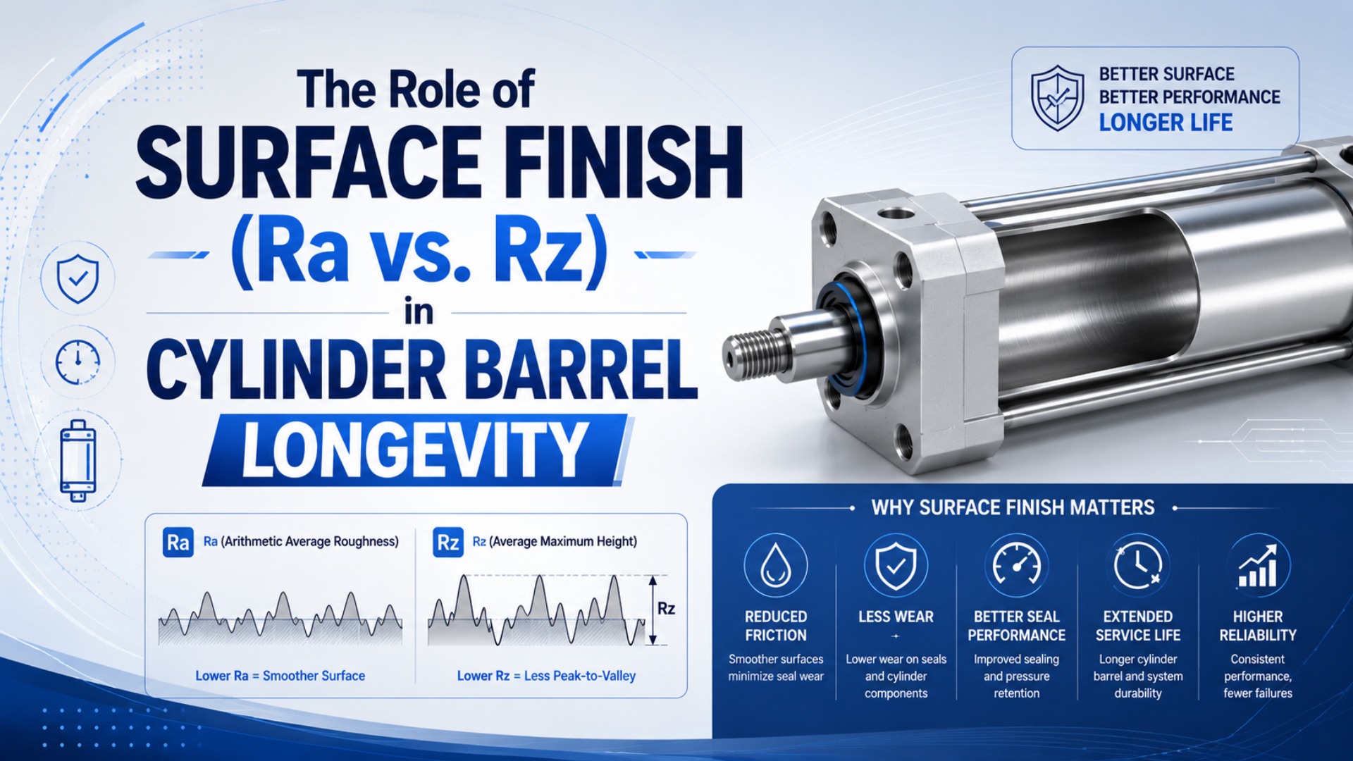
Cylinder barrel longevity depends on a complete surface-texture specification that matches the piston seal, barrel material, lubricant regime, and measurement method. Ra describes an average. Rz exposes more of the profile height, but neither value alone proves that a bore is free from sharp peaks, axial scratches, waviness, taper, or poor material support.
Parker’s pneumatic seal catalogue makes the dependency visible. Its dynamic-surface examples list Ra 0.2 µm / Rz 1.0 µm for rubber and PTFE products, but Ra 0.4 µm / Rz 1.6 µm for polyurethane products (Parker Pneumatic Seals, accessed 2026). Those are supplier examples for defined products, not universal pneumatic-cylinder limits.
That distinction matters during purchasing and failure analysis. A certificate showing one Ra result near the open end of a tube cannot describe the full seal path. It also cannot show whether the instrument, filter, evaluation length, trace direction, and measurement locations matched the drawing.
Key Takeaways
- ISO 21920-2:2021 defines profile-surface terms and parameters; ISO 21920-3:2021 defines the complete specification operator.
- Parker publishes different Ra/Rz examples for different pneumatic seal families, so there is no universal Ra-to-Rz conversion or best finish.
- Accept a barrel from a location-based inspection report, not from one roughness number or a visual claim that the bore is mirror smooth.
If you need the manufacturing-process view first, use the cylinder barrel honing guide. This article stays on the narrower question: what Ra and Rz tell you, what they leave out, and how to turn them into an inspectable cylinder-barrel requirement.
Ra and Rz: What Each Parameter Measures
ISO 21920-2:2021 contains the current published ISO terms, definitions, and parameters for profile surface-texture measurement, replacing ISO 4287:1997. Under that framework, Ra is calculated over the evaluation length, while Rz is averaged from maximum profile heights determined over the specified section lengths (ISO 21920-2, 2021).
Ra compresses the positive and negative departures of a roughness profile into one arithmetic average. In source form, the relationship is:
Here, is arithmetic mean height, is the evaluation length, and is the profile height relative to the mean line at position . The equation explains why isolated peaks and valleys can lose their identity inside an average. It does not predict seal life.
Rz adds information about vertical profile span across the specified section lengths. ISO 21920 renamed the older “sampling length” concept as section length and changed most parameters, including Ra, to evaluation-length calculation; peak parameters such as Rz retain section-based averaging (Digital Surf ISO 21920 Guide, accessed 2026). Taylor Hobson also distinguishes current Rz from Rz (JIS) and older ten-point conventions (Taylor Hobson Surface Finish Amplitude Parameters, 2022).
| Parameter | What it summarizes | What it cannot prove by itself |
|---|---|---|
| Ra | Mean absolute profile-height departure | Peak sharpness, one deep valley, lay, scratches, or waviness |
| Rz | Averaged peak-to-valley height behavior under defined section-length rules | Whether the feature repeats, where it occurs, or whether the seal material accepts it |
| Rp | Maximum profile peak height above the mean line | Valley structure or supporting material area |
| Rmr | Material ratio at a stated section level | Bore diameter, roundness, taper, cleanliness, or coating integrity |
What should an engineer remember? Ra is a screening statistic. Rz is another view of the same measured profile, not a substitute for the profile, its location, or the measurement specification.
Why Can Two Cylinder Bores With the Same Ra Behave Differently?
Parker shows several dynamic surfaces with nearly identical Ra values but visibly different profiles, then recommends evaluating multiple parameters for reciprocating seals. Its current engineering guide uses Ra, Rp, Rz, and Rmr because one average cannot distinguish a plateau from damaging peaks (Parker Performance Sealing Products, accessed 2026).
Imagine three bores that all pass the same Ra limit. The first has many small, evenly distributed features. The second has broad plateaus interrupted by isolated peaks. The third contains a directional groove aligned with piston travel. Their averages may be close, but the seal sees three different contact conditions.
This is where “smoother is always better” breaks down. A low Ra does not confirm lubricant retention or rule out a long scratch. Nor does a higher Ra automatically mean failure. The selected seal profile and compound set the counter-surface requirement.
The barrel also has geometry outside roughness. Taper changes seal squeeze along the stroke. Ovality changes it around the circumference. Waviness can alter contact over a longer spacing than the roughness filter retains. A profilometer reading and bore-gauge results answer different questions.
A useful acceptance package separates three layers: bore size and form, filtered surface-texture parameters, and unfiltered defect evidence. Passing one layer cannot compensate for failing another. That separation is more valuable than adding decimal places to Ra.
Can Ra Be Converted Directly to Rz?
No universal conversion is defensible. Parker’s pneumatic examples pair Ra 0.2 µm with Rz 1.0 µm for rubber/PTFE and Ra 0.4 µm with Rz 1.6 µm for polyurethane, already producing different ratios within one catalogue (Parker Pneumatic Seals, accessed 2026).
A ratio is only a correlation for a known family of surfaces produced and measured in a known way. Change the honing stone, feed, pressure, barrel material, coating, filtering, or defect population and the relationship can move. That is why converting a supplier’s Ra result into an invented Rz value creates false precision.
Older documents make the situation more confusing. Parker’s O-Ring Handbook discusses an Rz definition based on five consecutive trace lengths under older DIN practice, while Taylor Hobson distinguishes current Rz, Rz1max, and Rz (JIS). The same symbol can therefore be misunderstood when a drawing omits the standard and edition.
Use this decision rule:
- If the seal supplier specifies both Ra and Rz, measure and report both.
- If the drawing specifies only Ra, do not calculate Rz from a generic multiplier. Ask whether a supporting peak, material-ratio, or maximum-height limit is required.
- If an old drawing cites ISO 4287, DIN 4768, or a JIS convention, preserve the legacy requirement until engineering formally translates it to the current specification system.
- If supplier and customer standards conflict, resolve the measurement convention before production, not after a failed inspection.
Would two values on a certificate solve the problem? Not yet. They must come from the right place on the bore and from the same specification operator used to define the tolerance.
Drawing Requirements for a Verifiable Bore Finish
ISO 21920-1:2021 defines how profile surface texture is indicated in technical product documentation, while ISO 21920-3:2021 defines the complete specification operator used to decide compliance. A drawing therefore needs more than one number beside a roughness symbol (ISO 21920-1; ISO 21920-3, 2021).
Start with the functional interface. Identify the barrel drawing revision, bore material or coating, piston-seal profile and compound, intended lubricant policy, pressure range, speed range, temperature, and duty cycle. A generic material label such as “PU seal” is not enough when the supplier offers several profiles or compounds.
Then define the surface-texture requirement:
- Governing standard and edition. State ISO 21920 or the approved ASME/legacy system. Do not mix symbols and default rules from different systems without an engineering note.
- Required parameters and limits. Use the exact seal manufacturer’s values. Parker’s broader reciprocating guidance uses Ra, Rp, Rz, and Rmr as a functional group, but another product may require a different set.
- Filter and nesting-index settings. These separate shorter-spacing roughness from longer-spacing waviness. The chosen settings affect the reported result.
- Evaluation and sampling rules. State the length or the standard defaults that apply, plus any rule for multiple traces and maximum results.
- Trace direction. Measure in the direction required by the drawing. For a honed bore, record how the trace relates to the machining lay and piston travel.
- Measurement locations. Define axial stations, circumferential positions, excluded edges, and how the far end of a blind or assembled bore will be accessed.
- Separate defect criteria. Give acceptance rules for axial scratches, dents, pits, coating loss, embedded abrasive, corrosion, and damaged lead-in edges.
- Bore geometry. Specify diameter, taper, roundness, straightness, cylindricity, or other form controls independently from roughness.
ASME B46.1-2019 (R2026) remains an alternative surface-texture framework. ASME describes it as covering roughness, waviness, lay, and the parameters used to specify geometric surface irregularities (ASME B46.1, reaffirmed 2026). Use the system required by the contract, then keep the drawing, instrument setup, and report inside that system.
For tube procurement details beyond texture, the honed cylinder tube guide covers material, bore tolerance, straightness, cleaning, and RFQ information.
How Should Surface Finish Be Measured Inside a Cylinder Barrel?
ISO 25178-601:2025 now defines design and metrological characteristics for contact stylus instruments used for areal topography, and it also applies when profile measurements are extracted from areal data. ISO lists it as the published replacement for ISO 3274:1996 (ISO 25178-601, 2025).
Instrument access is the first practical limit. A portable roughness tester may reach the open end but not mid-stroke or the far end. A right-angle or bore probe may be needed. If the stylus cannot follow the required trace without skidding, tilting, or colliding with the wall, the result is not automatically comparable with an accessible flat calibration specimen.
Use a controlled sequence:
- Clean the barrel without polishing away evidence. Record abrasive residue, corrosion protection, and handling condition.
- Verify instrument status using a traceable reference appropriate to the expected roughness range. Taylor Hobson recommends a calibration standard close to the value being measured rather than relying on a much rougher reference (Taylor Hobson Surface Finish Calibration Methods, accessed 2026).
- Enter the governing standard, parameter set, filters, evaluation length, stylus details, and any non-default settings.
- Establish a location map. Measure near both ends and at one or more mid-stroke stations, with circumferential traces where the drawing or failure pattern requires them.
- Preserve directional evidence. Record where the port, guide load, rod side, or carriage load sits relative to each trace.
- Inspect defects separately with suitable lighting, magnification, or a borescope. Do not average a scratch into a normal roughness result.
- Pair texture readings with bore diameter and form measurements at corresponding locations.
- Run the specified cleaning, leak, and motion checks after assembly.
In our experience, a location map catches more repeat-failure causes than a single “best” trace. If one side of the seal and guide shows matching wear, compare the roughness and bore form at that clock position before changing compounds. The rod bearing and seal failure guide explains why guidance errors can imitate a surface-finish problem.
How Does Surface Finish Influence Cylinder Longevity?
ISO 19973-3:2015 reports pneumatic-cylinder lifetime in cycles or kilometres under defined reliability tests. It does not assign a universal life multiplier to Ra or Rz. Any claim such as “three times longer life” therefore needs matched cylinders, operating conditions, samples, and failure criteria (ISO 19973-3, confirmed 2021).
Surface finish influences longevity through contact, lubrication, and leakage paths. High or sharp peaks can abrade a dynamic seal. A groove aligned with travel may connect pressure regions. Inadequate supporting area can concentrate contact, while the wrong texture for the selected lubricant regime can contribute to stick-slip or unstable breakaway.
Those mechanisms do not operate alone. Seal profile and compound, piston guidance, side load, bore geometry, air cleanliness, pressure, speed, temperature, stroke, reversals, dwell, assembly damage, and lubricant policy can all change the result. The dynamic and static cylinder seal guide separates moving seal interfaces from fixed joints, and the seal material selection guide covers compound-dependent limits.
| Evidence found | Plausible surface-related mechanism | Checks needed before blaming roughness |
|---|---|---|
| Rapid, evenly distributed lip wear | Abrasive profile or contaminated surface | Seal identity, air quality, lubricant, speed, temperature |
| One deep cut in the seal | Isolated peak, burr, or axial scratch | Bore lighting, borescope, location-matched profile trace |
| Internal bypass after a rebuild | Groove, scoring, seal damage, or bore-form error | Connected valve path, seal orientation, ID, taper, roundness |
| Jerky start followed by smoother travel | Breakaway friction or guide/load issue | Pressure at the cylinder, flow control, alignment, side load, lubrication |
| Wear concentrated on one side | Uneven guidance or local bore condition | Piston guide, rod bearing, mounting, clock-position measurements |
If air passes between chambers, follow a controlled internal cylinder leakage diagnosis before ordering another seal kit. Surface data should narrow the fault tree, not replace it.
ISO 19973-1:2015 also requires reliability assessment to use declared test conditions and statistical evaluation (ISO 19973-1, 2015). A defensible comparison records cylinder series, bore, stroke, seal, pressure, speed, load, air quality, temperature, lubrication, sample size, test duration, permitted maintenance, and first-failure threshold.
The strongest surface-finish evidence is a traceable chain, not a low number: drawing requirement, instrument configuration, location-based results, defect and geometry record, then leakage and motion performance. Break any link and the surface certificate becomes weak evidence for longevity.
What Should a Cylinder Barrel Inspection Report Contain?
Parker’s reciprocating-seal guidance uses 4 complementary texture parameters, Ra, Rp, Rz, and Rmr, while ASME B46.1 separates roughness, waviness, and lay. A useful barrel report must preserve those distinctions and connect every result to a location, instrument setup, drawing revision, and acceptance decision (Parker; ASME, accessed 2026).
At minimum, request:
- customer and supplier part numbers, barrel serial or batch identity, and drawing revision;
- barrel material, coating or anodized condition, bore size, and seal identification;
- governing surface-texture standard, edition, parameters, tolerance limits, and acceptance rule;
- instrument model, probe or stylus details, software version where relevant, calibration or verification status;
- filter, nesting index or cutoff, evaluation length, trace direction, and any non-default settings;
- axial and circumferential measurement-location map with individual results, not only an average;
- bore diameter and specified form results at corresponding stations;
- visual or borescope findings for scratches, pits, coating damage, debris, and lead-in edges;
- cleaning method, preservation condition, ambient conditions when required, and operator/date traceability;
- final leak, breakaway, and motion-test results for the assembled cylinder when the control plan requires them.
Averages can still be useful for process control, but don’t let them hide the worst accepted location. When the drawing contains a maximum rule, report the individual result that controls acceptance. When it uses a population rule, identify the sample and decision method.
For a replacement RFQ, send the failed seal and bore evidence together. Photos should preserve orientation. Mark the installed clock position, direction of travel, and where the symptom occurs. That package helps a supplier distinguish surface damage from the load-path and contamination problems covered in the related maintenance guides.
Cylinder Barrel Surface Finish FAQs
Parker publishes at least 2 different dynamic Ra/Rz examples in one pneumatic seal catalogue, while ISO 21920 separates parameter definitions from the compliance operator. These 5 answers keep Ra, Rz, measurement settings, seal identity, and service evidence connected instead of assigning one universal cylinder-bore finish (Parker; ISO 21920-3).
Is a lower Ra always better for a pneumatic cylinder barrel?
No. Lower Ra does not show peak sharpness, deep valleys, directional scratches, waviness, material ratio, or bore geometry. It may also conflict with the lubrication needs of the selected seal. Start with the exact seal manufacturer’s counter-surface requirement, then specify the governing standard, supporting parameters, and measurement settings.
What is the correct Ra-to-Rz conversion factor?
There is no universal factor. The ratio depends on the surface profile, manufacturing process, material, filtering, and parameter definitions. Parker’s own pneumatic examples do not use one constant ratio across seal families. Measure both parameters when both are required; don’t calculate an acceptance result from a generic multiplier.
Can a portable profilometer inspect the whole cylinder bore?
Only when the probe can reach every required location and follow the specified trace without collision, tilt, or skid-related distortion. An easy reading near the tube entrance cannot represent mid-stroke or the far end. Define access, locations, stylus configuration, and calibration checks in the inspection plan before measurement begins.
Are scratches included in Ra and Rz acceptance?
Do not rely on Ra or Rz to accept scratches. A long axial scratch can be functionally serious even when the surrounding profile meets its roughness limits. Put scratches, pits, burrs, coating loss, and embedded debris under separate visual or defect criteria, then record their position relative to seal travel.
How can a supplier prove that surface finish increased cylinder life?
Use a controlled reliability comparison with declared cylinders, seals, pressure, speed, stroke, load, air quality, lubrication, temperature, samples, and failure thresholds. ISO 19973-3 reports cylinder life in cycles or kilometres under defined tests. A single customer anecdote, Ra certificate, or months-in-service claim cannot isolate surface finish as the cause.
Sources and technical references
- ISO 21920-1:2021, Geometrical product specifications (GPS) - Surface texture: Profile - Part 1: Indication of surface texture, drawing-indication rules for profile surface texture; retrieved 2026-07-22.
- ISO 21920-2:2021, Geometrical product specifications (GPS) - Surface texture: Profile - Part 2: Terms, definitions and surface texture parameters, current published ISO profile-parameter terminology; retrieved 2026-07-22.
- ISO 21920-3:2021, Geometrical product specifications (GPS) - Surface texture: Profile - Part 3: Specification operators, complete specification operator for compliance; retrieved 2026-07-22.
- ISO 25178-601:2025, Geometrical product specifications (GPS) - Surface texture: Areal - Part 601, contact stylus instrument characteristics applicable to areal and extracted profile measurements; retrieved 2026-07-22.
- ASME B46.1-2019 (R2026), Surface Texture (Surface Roughness, Waviness, and Lay), US surface-texture terminology and specification framework; retrieved 2026-07-22.
- Parker Pneumatic Seals, PTD3351, product-family examples for dynamic sealing surfaces and material-ratio limits; retrieved 2026-07-22.
- Parker Performance Sealing Products, 5371, Ra, Rp, Rz, and Rmr guidance for reciprocating sealing surfaces; retrieved 2026-07-22.
- Parker O-Ring Handbook, PTD5705, legacy roughness terminology and the need to identify the governing convention; retrieved 2026-07-22.
- Taylor Hobson, Surface Finish Amplitude Parameters, Ra, Rz, Rz1max, and Rz (JIS) distinctions; retrieved 2026-07-22.
- Taylor Hobson, Surface Finish Calibration Methods, calibration-standard selection near the measured roughness range; retrieved 2026-07-22.
- Digital Surf, ISO 21920 Surface Metrology Guide, evaluation-length and section-length changes from ISO 4287 practice; retrieved 2026-07-22.
- ISO 19973-1:2015, Pneumatic fluid power - Assessment of component reliability by testing - Part 1, general procedures, test conditions, statistical evaluation, and reporting; retrieved 2026-07-22.
- ISO 19973-3:2015, Pneumatic fluid power - Assessment of component reliability by testing - Part 3, reliability testing and lifetime reporting for pneumatic cylinders with piston rods; retrieved 2026-07-22.