

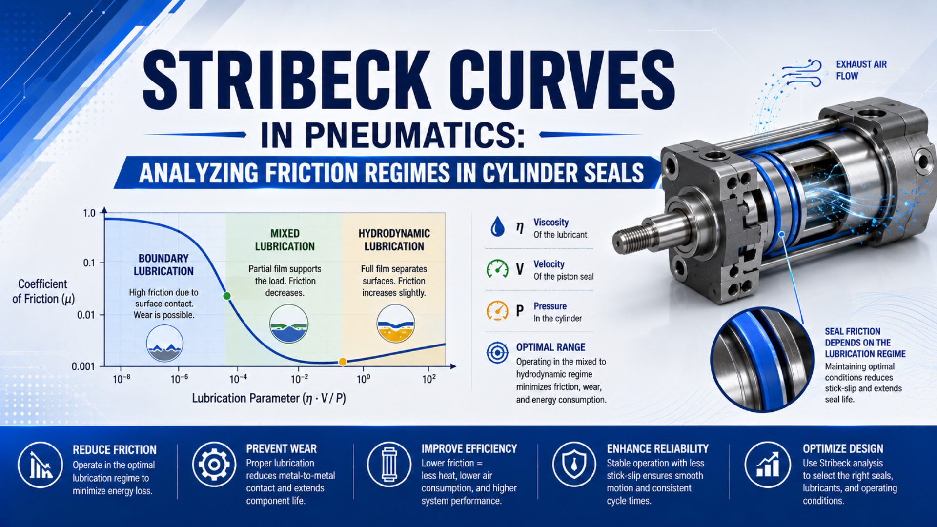
Stribeck curves in pneumatics are empirical maps of friction against speed or a defined lubrication parameter for one seal configuration under controlled pressure, temperature, lubrication, direction, and motion history. They help engineers distinguish breakaway, falling low-speed friction, and velocity-dependent drag. They do not supply universal regime boundaries for every cylinder.
A 2019 study of commercial pneumatic cylinders tested piston and rod seals separately. In those arrangements, piston seals produced 90% of measured cylinder friction, while pressure influenced friction more strongly than velocity. The result demonstrates why a useful map must identify the tested hardware and conditions rather than assign one coefficient to “NBR,” “polyurethane,” or “PTFE” (Azzi et al., 2019).
Key Takeaways
- Plot measured friction force against velocity first; calculate a friction coefficient only when seal contact load is known.
- Do not call dimensionless. With viscosity in Pa·s, speed in m/s, and pressure in Pa, the expression has units of length.
- Separate extension, retraction, breakaway, steady sliding, reversal, and dwell. Combining them can hide the behavior the test is meant to reveal.
- Pressure, seal profile, diameter, grease, counterface, temperature, wear, and external guidance can move or reshape the curve.
- A Stribeck-type fit can support control and comparison, but it cannot prove leakage performance or service life.
What Does a Stribeck Curve Mean for a Pneumatic Cylinder Seal?
The 2019 pneumatic-seal experiments varied pressure, velocity, seal profile, diameter, and stroke direction, then found strong interaction among those inputs. For a cylinder engineer, the curve is therefore a condition-specific friction map, not a material lookup table. Its value lies in comparing controlled states and locating unstable low-speed behavior (Azzi et al., 2019).
The classical Stribeck concept describes how a lubricated contact moves from substantial asperity interaction toward increasing film support as speed and lubricant entrainment rise relative to load. Friction commonly falls through part of that transition and may rise again when viscous shear becomes important. That recognizable shape is useful, but a pneumatic cylinder seal differs from the journal bearing used in many textbook explanations.
A cylinder seal is soft, pressure-energized, reciprocating, and continually reversing. Its lip deforms against a honed tube or rod. Grease is finite and redistributed by each stroke. Surface roughness creates local film-thickness variation, while the seal can see different contact gradients in the two directions. Research on reciprocating elastomeric seals describes simultaneous boundary and fluid-film behavior across different microscopic regions of the same contact (Bisztray-Balku, 1999).
That makes three terms worth separating:
- Stribeck curve: a general tribology relationship between friction and a defined lubrication parameter.
- Stribeck-type friction map: measured cylinder or seal friction plotted against speed, pressure, or a configuration-specific normalized variable.
- Stribeck friction model: an equation fitted to reproduce a falling low-speed friction component, normally combined with Coulomb and viscous terms for simulation or control.
Do not label every point “boundary,” “mixed,” or “hydrodynamic” from speed alone. Direct film-thickness or contact evidence is needed to assign a physical lubrication regime confidently. A friction minimum by itself is not proof of complete fluid-film separation.
Is the Stribeck Parameter Really Dimensionless in Pneumatic Seal Testing?
A 1999 reciprocating-seal review related film thickness to lubricant viscosity, sliding velocity, and the gradient of sealing-pressure distribution, not chamber pressure alone. This matters because the frequently repeated expression has units of length. It becomes dimensionless only after a valid geometric or load normalization is defined (Bisztray-Balku, 1999).
The dimensional check is straightforward. Dynamic viscosity has units of Pa·s, velocity has units of m/s, and pressure has units of Pa:
Calling that ratio dimensionless drops a length scale. One possible seal-specific duty parameter is:
Here is an average contact pressure and is the seal contact width. The ratio is dimensionless, but it is usable only when the definitions and estimation method for and are disclosed. Chamber air pressure is not automatically the seal’s average contact pressure. Interference creates preload, and pressure energization changes the lip contact distribution.
For most plant investigations, a friction-force map is more defensible than a universal coefficient curve. Record friction force in newtons against velocity at each chamber-pressure, direction, temperature, and dwell condition. This avoids inventing an effective normal load that cannot be measured from the assembled cylinder.
Use a coefficient only when the experiment or validated contact model supplies an effective normal force:
The result is an effective value for that model boundary, not an intrinsic material constant. Surface finish, grease, seal geometry, radial interference, pressure, and temperature remain part of its identity.
Variables That Reshape Pneumatic Seal Friction
Azzi and colleagues tested commercial cylinders and found pressure more influential than velocity in their configurations; their piston and rod seals also responded to profile, diameter, and motion direction. A useful Stribeck-type map must therefore hold the non-plotted variables constant or represent them as separate curve families (Tribology International, 2019).
| Variable | Why friction changes | What to control or record |
|---|---|---|
| Chamber pressure | Pressure energizes lips and changes contact stress | Both cylinder-port pressures, not regulator setting alone |
| Velocity | Changes lubricant entrainment, shear, and time for seal deformation | Signed velocity and stable-speed window |
| Direction | Lip orientation, rod area, load, and film transport differ | Separate extension and retraction curves |
| Dwell | Adhesion, elastomer relaxation, and grease redistribution alter breakaway | Previous direction and fixed dwell intervals |
| Temperature | Changes grease viscosity, elastomer response, dimensions, and recovery | Cold-start and stabilized seal-housing temperature |
| Seal geometry | Lip angle, contact width, interference, and energization differ | Exact profile, compound, groove, and production revision |
| Counterface | Roughness, waviness, coating, scratches, and contamination affect film and wear | Tube or rod specification plus inspected condition |
| Alignment | Side load changes local contact stress and adds guide friction | Mount, external guide, load center, and rod reactions |
| Wear history | Lip shape, preload, roughness, and grease quantity evolve | Cycles or travel, conditioning procedure, and inspection state |
Parker’s PTFE design guide illustrates why a material-only ranking fails. Its Slipper Seal uses a polymer ring plus an elastomeric O-ring energizer. The energizer supplies low-pressure contact and adds pressure-dependent loading, while the PTFE-based ring provides the sliding surface. Changing the O-ring, interference, groove, filler, or pressure changes the system even if the visible sealing material is still called PTFE (Parker PTFE Seals Design Guide).
Water contamination should not be treated as the intended lubricant. Pneumatic seals commonly depend on assembly grease, transferred lubricant, or a profile designed for the approved lubrication condition. Condensate can dilute or displace grease and promote corrosion. Check air quality and the exact cylinder instructions before adding airline oil or changing grease.
For a deeper material and temperature screen, use the cylinder seal temperature guide. When the symptom is a high first-motion threshold after a stop, the breakaway-force guide provides the separate starting-force workflow.
A Repeatable Stribeck-Type Friction Test Method
A 2026 study measured position and both chamber pressures at 1.16 ms intervals, then estimated equivalent friction through the piston force balance. Its authors also warned that guide friction was included in the result. That distinction should govern every plant test: measure the complete resistance first, then isolate components only with additional fixtures (Ngoc et al., 2026).
Begin with a guarded test fixture and the machine’s approved energy-control procedure. Pneumatic breakaway tests store energy before motion begins. Secure the payload, define hard travel limits, verify sensor ranges, and keep personnel outside the movement envelope.
For extension defined as the positive direction, an equivalent opposing force can be estimated as:
The cap-end pressure acts on full piston area . Rod-end pressure acts on annular area . External force and acceleration must follow the same sign convention, while includes the accelerated cylinder and load mass represented by the model. The calculated may contain piston-seal, rod-seal, bearing, external-guide, cable, hose, and alignment resistance.
At stable velocity, the inertia term approaches zero. It cannot be discarded during acceleration, deceleration, reversal, or stick-slip. Numerical differentiation also amplifies position noise, so document the sampling, filtering, and time alignment used for every signal. Never smooth away the breakaway peak and then describe the filtered value as static friction.
Use this sequence for a repeatable map:
- Freeze the configuration. Record cylinder code, bore, rod, stroke, seal profile, compound, groove revision, lubricant, mount, guide, load, tubing, valve, and cushions.
- Condition the assembly. Define prior strokes, speed, temperature stabilization, and whether the test starts from new, run-in, or worn condition.
- Define dwell and first motion. Use fixed dwell intervals and a documented displacement or velocity threshold.
- Measure both ports. Install synchronized pressure sensors close enough to the cylinder to capture chamber behavior rather than regulator pressure alone.
- Acquire position and force evidence. Use a calibrated linear sensor; add a load cell when the fixture permits direct resistance measurement.
- Sweep speed in both directions. Use controlled plateaus or slow ramps, retaining enough stable travel outside cushion zones.
- Repeat pressure states. A single velocity sweep cannot show pressure energization.
- Repeat and preserve scatter. Plot individual cycles or confidence bands instead of presenting one smoothed line as exact behavior.
- Inspect after testing. Record temperature, leakage, grease movement, surface marks, particles, and one-sided wear before cleaning.
The cylinder force-loss guide explains the two-port force balance in more detail. If an external guide or side load is suspected, test it separately before attributing the entire residual to the seals.
Interpreting Curve Features Without Overdiagnosis
The 2026 three-cylinder investigation found that airflow, source pressure, external load, initial position, chamber volume, and dwell-dependent static friction all affected stick-slip. A negative low-speed friction slope may participate, but the complete oscillation is a pneumatic-system event involving pressure accumulation and release, not seal friction acting alone (Ngoc et al., 2026).
Start by separating observations that are often combined:
| Curve feature | Defensible interpretation | What it does not prove |
|---|---|---|
| High force at first movement | Breakaway resistance for the stated dwell and history | A fixed static-to-kinetic friction ratio |
| Friction falls as speed rises | Stribeck-like low-speed behavior in that test | Exact boundary-to-mixed transition |
| Friction reaches a minimum | A measured operating minimum | Complete fluid-film separation |
| Friction rises at higher speed | Viscous shear, seal deformation, pressure, or other speed-linked loss may be increasing | One universal hydrodynamic regime |
| Extension and retraction differ | Directional seal, area, load, alignment, or film-transport effects | A defective seal without further inspection |
| Curve moves after warm-up | Temperature or lubricant redistribution affects the assembly | The seal material alone caused the shift |
| Scatter grows near zero speed | Reversal, dwell, sensor noise, pressure dynamics, or stick-slip needs resolution | Random variation that can be averaged away |
Treat the result as a surface, not one curve. Velocity can occupy one axis, while pressure, direction, temperature, dwell, and wear state define separate slices. The approach prevents a low-friction curve measured warm in one direction from being used to predict a cold start after an eight-hour shutdown.
Hysteresis is useful evidence. If acceleration and deceleration sweeps do not follow the same path, the interface retains history through lubricant transport, thermal state, viscoelastic response, or presliding behavior. Do not force both branches into one static equation before confirming that the intended controller can tolerate the lost information.
When motion repeatedly stops and restarts, inspect chamber-pressure traces alongside position. Pressure rising during each stationary interval and dropping when motion resumes indicates stored pneumatic energy interacting with resistance. The dedicated stick-slip diagnostic covers the valve, flow-control, load, and compressibility checks that a seal-only map cannot replace.
Applying Stribeck Analysis to Seal Selection and Control
Parker describes its Slipper Seal as two functional elements: a low-friction polymer ring and an elastomeric energizer that maintains contact and responds to pressure. That construction shows the right design logic. Engineers should optimize the complete sealing system across leakage, friction, wear, chemistry, and tolerance, not pursue the lowest point on one curve (Parker).
Use measured maps for four decisions:
Define the operating window. Overlay the commanded speed, pressure, temperature, direction, and dwell envelope on the tested data. If production spends most of its time in a high-scatter region, moving the operating point may be easier than designing a complex friction compensator.
Compare seal configurations. Test the baseline and candidate with identical hardware, lubricant quantity, conditioning, temperature, pressure, speed sequence, and acceptance limits. A lower friction value is meaningful only if internal leakage, external leakage, wear, and low-pressure sealing still pass.
Improve the mechanical system. Check guidance and alignment before redesigning the lip. A side-loaded rod or carriage can change local seal pressure and add bearing resistance. A new seal cannot correct a bent rod, barrel defect, off-axis load, dragging cable carrier, or misaligned external guide.
Fit a control model. A Stribeck, LuGre, or other dynamic friction model can reproduce selected behavior after its parameters are identified from data. The 2026 study found that including dwell-dependent static friction improved stick-slip prediction compared with a velocity-driven model alone. Keep the model’s validated pressure, load, cylinder, and temperature range attached to its parameters.
Do not release a design from friction data alone. ISO 19973-3 covers test procedures and reporting for reliability assessment of pneumatic piston-rod cylinders and expresses life in cycles or kilometres. It is not a Stribeck-test standard, but its emphasis on defined equipment, thresholds, conditions, and reporting is a sound template for durability evidence (ISO 19973-3:2015).
| Approval item | Evidence required |
|---|---|
| Breakaway | Force by direction, dwell, temperature, and first-motion definition |
| Running friction | Speed-pressure map with repeatability and filter details |
| Motion quality | Velocity variation, stops, reversal response, and pressure traces |
| Leakage | Internal and external methods, pressures, stabilization, and limits |
| Durability | Cycles or travel, duty, inspection intervals, and failure thresholds |
| Hardware condition | Seal, bore or rod, guide, lubricant, particles, and wear records |
| Traceability | Part code, seal lot, drawing revision, sensor calibration, and raw data |
In our experience with replacement reviews, the most useful request is not “supply a lower-friction seal.” It is a bounded requirement: identify the cylinder, motion profile, pressure range, temperature, air quality, lubricant, dwell, measured force traces, leakage limit, and life target. That gives the seal or cylinder supplier enough evidence to approve a configuration rather than guess from a polymer name.
The piston-seal breakaway-friction guide explains how to compare two seal designs without hiding the baseline. Publisher details and a route for technical corrections are available through About Us and Contact.
Pneumatic Seal Stribeck Curve FAQs
The 2019 seal study separated piston and rod friction, while the 2026 system study measured three cylinders and incorporated dwell-dependent static friction. Together they show why pneumatic Stribeck analysis must preserve hardware, pressure, direction, and motion history instead of applying one universal curve (Azzi et al.; Ngoc et al.).
What should be on the axes of a pneumatic seal Stribeck curve?
Start with measured equivalent friction force on the vertical axis and speed magnitude on the horizontal axis. Create separate traces for pressure, direction, temperature, and dwell. Use friction coefficient or a dimensionless duty parameter only when the effective contact load, contact width, viscosity, and normalization method are available and documented.
Can chamber pressure replace seal contact pressure in the Stribeck parameter?
No. Chamber pressure can energize a seal, but installed interference and lip geometry also create contact stress, and that stress is distributed rather than uniform. Chamber pressure remains an essential test variable; it is not automatically the average contact pressure required by a seal-level dimensionless model.
Does a friction minimum prove hydrodynamic lubrication?
No. A minimum proves only that the measured friction reached a minimum under those test conditions. Establishing a hydrodynamic regime requires appropriate film, contact, or validated model evidence. Reciprocating elastomeric seals can contain boundary and fluid-supported micro-regions simultaneously, particularly near reversals and across a rough counterface.
Why should extension and retraction curves be separated?
The effective piston areas differ, lip orientation can be directional, external load may reverse sign, and lubricant transport can change with stroke direction. Combining both directions can average away real asymmetry. Calculate each force balance with its own sign convention, then investigate differences in seals, guidance, alignment, and counterface condition.
Can a Stribeck model eliminate pneumatic cylinder stick-slip?
Not by itself. A fitted friction model can improve simulation or compensation inside its validated range, but stick-slip also depends on valve flow, air compressibility, chamber volume, pressure buildup, load, dwell, and control logic. Use synchronized position and two-chamber pressure traces to verify the system-level mechanism before changing controller parameters.
Sources and technical references
- Azzi et al., “Experimental study of friction in pneumatic seals”, Tribology International 135, 432-443, 2019; retrieved 2026-07-22.
- Ngoc, Pham, and Xuan, “Experimental and System-Level Simulation Study of Stick-Slip Characteristics in Pneumatic Cylinders”, Actuators 15(5), 243, 2026; retrieved 2026-07-22.
- Çelik and Kılıç, “Development of a Test Apparatus for Estimation of Friction Parameters at Linear Pneumatic Cylinders”, 2019; retrieved 2026-07-22.
- Bisztray-Balku, “Tribology of Elastomeric Seals”, Periodica Polytechnica Mechanical Engineering 43(1), 63-80, 1999; retrieved 2026-07-22.
- Bauer et al., “Elastohydrodynamic Simulation of Pneumatic Sealing Friction Considering 3D Surface Topography”, Chemical Engineering & Technology, 2023; retrieved 2026-07-22.
- Parker PTFE Seals Design Guide PTD3354, seal construction, contact loading, materials, and application limits; retrieved 2026-07-22.
- ISO 19973-3:2015, reliability testing and reporting for pneumatic piston-rod cylinders; retrieved 2026-07-22.