

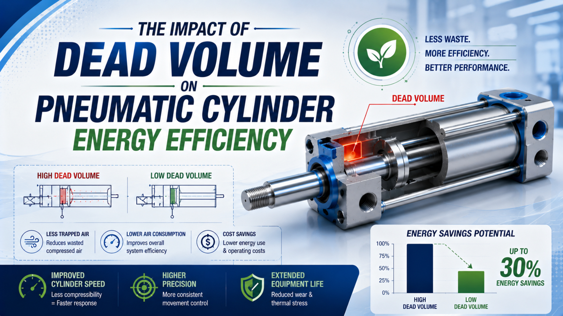
Dead volume affects pneumatic cylinder energy efficiency when a fixed cavity or line is repeatedly pressurized and exhausted without adding useful piston travel. Quantify that volume, convert its pressure change to standard-air demand, multiply by accepted cycles, and then verify the result with a flow meter. There is no universal 30% or 50% efficiency penalty.
The calculation boundary matters. Cylinder clearance, port drillings, valve-to-cylinder tubing, fittings, and connected valve passages can all add chargeable volume, but only when the valve state makes them part of the switched path. Supply headers upstream of the directional valve usually remain pressurized and should not be counted as though they refill every stroke.
Key Takeaways
- SMC’s published example combines 13 L (ANR) of cylinder air with 0.56 L of switched piping per cycle.
- Physical volume, standard-air consumption, and compressor electricity are different quantities.
- Pressure decay alone measures leakage, not unknown volume.
- Verify savings as standard air per accepted production cycle.
What Counts as Dead Volume in a Pneumatic Cylinder Circuit?
SMC defines cylinder air consumption to include air used inside the cylinder and in the piping between the cylinder and switching valve. Its worked example reports 13 L (ANR) for the cylinder and 0.56 L for the piping per cycle (SMC Air Cylinders Model Selection, accessed 2026-07-22).
Use three separate volume names:
- Clearance volume is the chamber space remaining when the piston reaches its mechanical end position. It can include the end-cap pocket, cushion passages, port drilling, and the unavoidable gap between the piston and end cap.
- Switched line volume is the connected tube, hose, fitting, speed controller, manifold passage, and valve passage that changes pressure when the directional valve switches.
- Swept volume is the effective piston area multiplied by stroke. It changes as the piston moves and produces mechanical displacement.
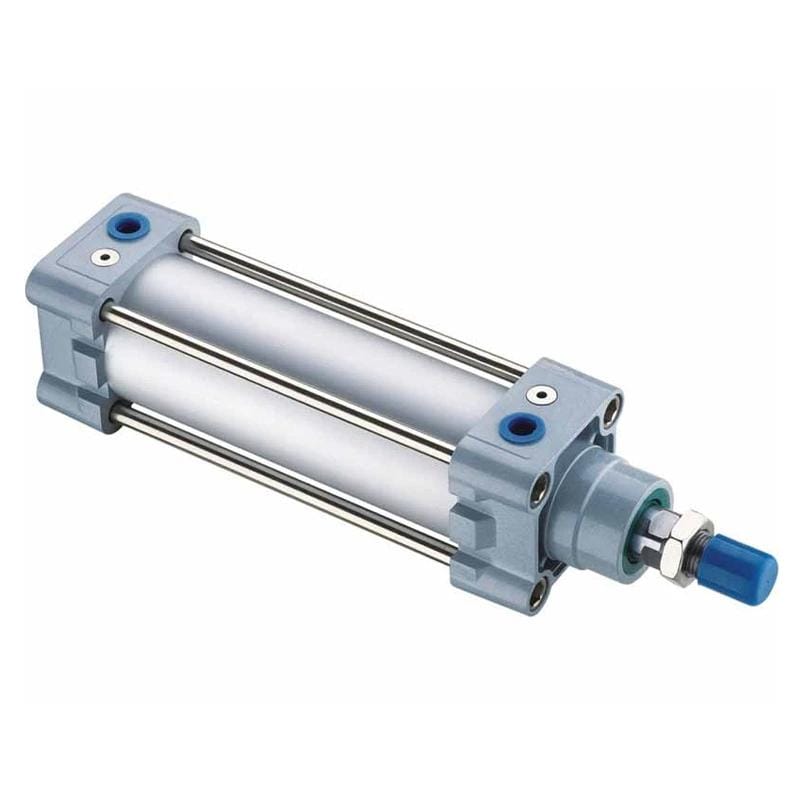
DNC Series ISO-style pneumatic cylinder
Calling every internal space “dead volume” creates bad calculations. A valve supply gallery that stays at pressure isn’t consumed again on every cycle. A valve exhaust gallery may serve several ports. A cushion pocket can be connected differently as the piston enters the cushion zone. Trace the actual state-dependent path before adding volumes.
Dead volume also does not reduce the cylinder’s geometric stroke. The piston still sweeps the specified distance. The penalty is additional air mass, fill and exhaust time, and stored pneumatic energy associated with a fixed volume that does not create extra travel.
Single-rod cylinders are asymmetric because the rod reduces the effective area and chamber volume on one side. Rodless cylinders aren’t automatically symmetric or lower-volume; internal bands, carriage passages, end-cap geometry, cushions, and port routing vary by design. Use the selected model’s drawings or measured data.
For the timing effect of these same volumes, see the separate cylinder response-time and dead-volume analysis. This article keeps a different boundary: repeated standard-air consumption and verified energy impact.
How Do You Calculate the Air Added by Fixed Dead Volume?
SMC’s air-consumption equations use absolute-pressure ratio for swept cylinder chambers and gauge-pressure ratio for switched piping. In its 0.5 MPa example, 2 m of 6 mm-bore piping adds about 0.56 L (ANR) to each complete cylinder cycle (SMC, accessed 2026-07-22).
Start with physical tube volume:
is internal tube volume, is actual inside diameter, and is length. Keep units consistent. If both dimensions are in millimetres, divide cubic millimetres by 1,000 to obtain cubic centimetres.
For a fixed volume charged from an initial absolute pressure to a final absolute pressure, the added equivalent free-air volume is, under an isothermal screening assumption:
is the physical connected volume, and are final and initial absolute pressures, and is the selected reference pressure. State the reference temperature and standard-volume convention beside the result.
When the volume begins at atmospheric pressure, the numerator equals gauge pressure. This explains why a switched tube-volume term differs from a swept chamber term: the tube already contains air before charging, while the piston movement creates new chamber volume that must also be filled.
Count each fixed volume only when its pressure actually cycles. For one complete extend-and-retract cycle, the cap-side line and rod-side line are normally charged once each in a conventional 5/2 circuit. A center-closed, pressure-center, quick-exhaust, two-pressure, or early-cutoff circuit changes that boundary.
The Pneumatic Tube Volume Calculator can provide physical and equivalent free-air volume for a line. The Air Consumption Calculator supplies the swept-cylinder baseline. Neither tool knows the selected valve’s internal passages or end-cap clearance, so add documented fixed volumes separately.
A Worked SMC Example Shows the Real Scale
SMC’s published case uses ten 50 mm bore cylinders with 600 mm strokes, 0.5 MPa pressure, five cycles per minute, and 2 m of 6 mm-bore piping. It calculates 13 L per cylinder cycle plus 0.56 L for piping, for 678 L/min total demand (SMC, accessed 2026-07-22).
The volume of one 2 m line with 6 mm inside diameter is:
At 0.5 MPa gauge with a 0.1 MPa reference pressure, the additional free-air volume for one line is approximately:
Two lines give about 0.565 L, matching SMC’s rounded 0.56 L piping value. The complete per-cylinder cycle becomes:
| Component | Standard-air volume per cycle |
|---|---|
| Cylinder swept chambers | 13.00 L (ANR) |
| Two switched lines | 0.56 L (ANR) |
| Total | 13.56 L (ANR) |
The line share is approximately:
That is about 4.1% for this example. It is not a general dead-volume percentage. Smaller cylinders, shorter strokes, longer tubing, larger inside diameters, higher pressures, and more frequent cycling can make the fixed-volume share much larger. Conversely, a long-stroke large-bore cylinder may have a small line-volume share even though the absolute line consumption remains worth measuring.
The ratio is useful for prioritization, but the absolute standard-air reduction determines plant demand. Report both. A 20% fixed-volume share on an occasional small actuator may be less important than a 3% share on hundreds of high-cycle actuators.
The existing double-acting cylinder air-consumption guide covers the full swept-volume calculation. Use this article to isolate the fixed, repeatedly switched part of that total.
Why Air Savings and Electricity Savings Are Not the Same Percentage
CAGI states that a 2 psi increase in compressor discharge pressure raises required horsepower by about 1%, before artificial demand is included. Its 100-to-110 psig example reaches about 14% combined impact because pressure and demand both change (CAGI Compressed Air System Design, 2021).
This system dependence is why a 4.1% reduction in one cylinder’s calculated air per cycle does not automatically reduce the electricity bill by 4.1%. The result also depends on:
- how much of the plant’s total standard-air demand the modified cylinder represents;
- compressor type, specific power, unloading and modulation behavior;
- receiver storage and pressure-control strategy;
- leakage and other unregulated demand;
- production rate, idle time, and simultaneous pneumatic loads;
- whether reduced demand changes compressor sequencing or only increases unloaded time.
First calculate annual standard-air savings:
is the measured or calculated reduction per accepted cycle, and is the annual number of complete accepted cycles. Exclude rejected or diagnostic cycles only if the process change genuinely removes them; otherwise they remain part of demand.
Then estimate electricity using a measured site-specific energy intensity:
is compressor-system electricity per standard cubic metre or standard cubic foot delivered across the same measurement boundary. Obtain it from synchronized compressor power and delivered-air data. A generic electricity price alone cannot convert cylinder volume into energy.
ISO/TR 22165:2018 advises improving pneumatic-system efficiency while considering functionality and economic efficiency (ISO/TR 22165, confirmed 2026-07-22). Force, response, cushioning, safety, maintainability, and production quality therefore remain acceptance conditions, not optional checks after an air-saving change.
How Can Unknown Dead Volume Be Measured Correctly?
NIST’s PVTt flow standards use known collection-vessel volume together with pressure, temperature, time, and an equation of state. NIST also describes a separate volume-expansion method in which a known volume is pressurized, connected to an unknown evacuated volume, and solved from the resulting density change (NIST Gas Flow Standards, accessed 2026-07-22).
Use one of three methods, matched to the needed uncertainty:
- Geometric calculation. Calculate tube and simple drilled-passage volumes from measured dimensions. Use supplier CAD or drawings for end-cap and valve cavities. Record whether dimensions are nominal or measured.
- Reference-volume expansion. Connect a calibrated reference vessel to the isolated unknown volume, record initial and final absolute pressures and temperatures, allow thermal equilibrium, and solve conservation of mass.
- Cycle-normalized flow measurement. Measure accumulated standard air over a known number of repeated cycles, then compare configurations under the same load, pressure, timing, and valve state. This captures the complete circuit but does not identify each cavity by itself.
Under an ideal-gas, equal-temperature screening assumption, a reference volume initially at connected to an unknown volume initially at and equalized at gives:
is the unknown volume and is the calibrated reference volume. All pressures must be absolute. For defensible measurement, include temperature terms, connecting volume, leakage, sensor uncertainty, pressure-dependent component deformation, and adequate stabilization time. NIST’s detailed method uses density rather than the simplified equal-temperature pressure form (NIST SP 250-63).
Pressure decay alone cannot determine unknown volume. A decay trace combines leakage conductance, volume, absolute pressure, temperature change, and time. Without known volume or known leak flow, different volume-leak combinations can create similar curves. Use pressure decay to detect or quantify leakage after the test volume has been established.
Do not fill an assembled production cylinder with water merely to measure volume unless the manufacturer has approved the procedure and the component can be completely cleaned, dried, relubricated, and recommissioned. Water can contaminate grease, promote corrosion, damage seals, and leave an unsafe residual condition.
Measure the boundary the valve actually switches. A bench test that includes a long temporary hose, large isolation manifold, or test instrument cavity can report more “dead volume” than the production circuit contains. Conversely, excluding the installed fitting and speed controller understates the real cycled volume.
Which Dead-Volume Changes Deserve Priority?
Festo identifies repeatedly filling and exhausting long or large-diameter pipe runs as energy waste, and recommends moving valves closer to actuators. It also warns that smaller pipe diameters can restrict pressurization and exhaust, so tube size must still satisfy performance requirements (Festo, accessed 2026-07-22).
Prioritize changes by measured standard-air reduction and verified machine performance:
| Change | Volume or demand affected | Main check before acceptance |
|---|---|---|
| Move directional valve nearer the cylinder | Shortens switched line volume | Environment, wiring, service access, exhaust and safety zoning |
| Shorten unnecessary tubing loops | Reduces line volume without changing ID | Bend radius, movement, strain relief and maintenance access |
| Reduce tube inside diameter | Reduces volume strongly because area follows diameter squared | Dynamic pressure drop, fill time, exhaust time and cylinder speed |
| Use compact fittings or direct mounting | Removes connecting cavities | Flow coefficient, orientation, replacement access and vibration |
| Reduce end-cap or port cavity | Reduces cylinder clearance volume | Cushion capacity, piston clearance, manufacturability and strength |
| Lower verified working pressure | Reduces added air mass in fixed and swept volumes | Force, breakaway, acceleration, process load and supply dips |
| Remove unnecessary cycles | Eliminates the whole cycle demand | Production logic, diagnostics and fault recovery |
The valve-placement guide covers the central-versus-distributed architecture decision. A local valve can reduce line volume, but it may create new exposure to washdown, heat, vibration, inaccessible manual overrides, or unsafe stored-energy boundaries.
Don’t optimize line volume before checking larger demand sources. Leakage, an oversized bore, excess pressure, unnecessary stroke, idle pressurization, blow-off, and redundant motion can exceed the fixed-volume penalty. The bore-size and operating-cost analysis helps determine whether cylinder geometry, rather than line volume, controls consumption.
The best first target is not the largest percentage. Rank each candidate by annual standard-air reduction, implementation risk, and verified production impact. A short high-cycle clamp can justify a local valve before a long-stroke low-cycle transfer cylinder, even when the transfer cylinder has more physical volume.
A Before-and-After Verification Protocol
SMC’s worked example totals 678 L/min for ten cylinders, but the guide still calls for compressor allowance for temperature drop, leakage, and intermediary equipment. Calculated cylinder and piping volume is therefore a baseline, while final acceptance requires measured demand at the chosen machine boundary (SMC, accessed 2026-07-22).
Use the same procedure before and after one controlled change:
- Define the boundary. Name the cylinder branch, valve island, machine, or compressor system included in the measurement.
- Record the configuration. List cylinder model, bore, rod, stroke, valve model, fitting family, tube inside diameter and length, regulator setting, and control state.
- Stabilize the process. Use the same product, payload, cycle program, temperature, supply condition, and accepted-output criteria.
- Measure accumulated standard air. Divide the total by complete accepted cycles. Also record idle flow with the machine in its normal pressurized waiting state.
- Capture dynamic pressure. Measure valve-inlet pressure and both cylinder-port pressures during the highest-flow and highest-force portions of the stroke.
- Check timing and quality. Confirm command-to-motion delay, stroke time, cushioning, impact, repeatability, reject rate, and required force.
- Change one variable. Do not shorten tubing, lower pressure, repair leaks, and alter control logic in the same comparison if the goal is to isolate dead-volume savings.
- Repeat enough cycles. Report individual runs plus the mean or median and observed spread. Keep meter resolution and uncertainty with the result.
The acceptance metric is:
is standard-air volume per accepted cycle. is accumulated standard air across the defined boundary, and is the corresponding accepted-cycle count. A lower value is useful only when force, timing, safety, and product quality still pass.
Pneumatic Cylinder Dead Volume FAQs
SMC’s 0.5 MPa example assigns 0.56 L (ANR) to switched piping and 13 L to cylinder chambers per cycle. That 4.1% piping share belongs only to the stated 50 mm bore, 600 mm stroke, 2 m piping and pressure conditions (SMC, accessed 2026-07-22).
What is the difference between clearance volume and dead volume?
Clearance volume is the chamber space remaining at a mechanical end position. Dead volume is a broader application term that may also include connected port, fitting, tube, controller, manifold, and valve passages that are pressurized and exhausted without adding piston travel. State the circuit boundary whenever quoting either value.
Does dead volume reduce pneumatic cylinder force?
Not directly at steady pressure. Cylinder force follows the pressure difference acting on effective piston areas, minus mechanical resistance. Extra fixed volume can delay pressure buildup, increase air consumption, and store more pneumatic energy. A restricted path may also cause dynamic pressure loss, which can reduce force during motion.
Can pressure decay testing measure cylinder dead volume?
Not by itself. Pressure decay combines leakage, volume, temperature and time. To solve unknown volume, use measured geometry, a calibrated reference-volume expansion test, or a known mass-flow method with pressure and temperature data. Pressure decay becomes useful for leakage only after the connected test volume is known.
Will mounting the valve on the cylinder always save energy?
It usually removes part of the switched tube volume, but the complete result depends on cycle frequency, pressure, valve passages, pilot demand, exhaust routing and the previous tube length. The installation must also pass flow, timing, environment, electrical, service-access, stored-energy and machine-safety requirements.
How should dead-volume energy savings be reported?
Report calculated and measured standard-air reduction per accepted cycle, annual accepted cycles, idle flow, pressure, configuration, and measurement uncertainty. Convert air savings to electricity with site-specific compressor-system energy intensity. Do not report a universal percentage or annual cost without defining the complete calculation and measurement boundary.
Sources and technical references
- SMC, Air Cylinders Model Selection, cylinder and piping air-consumption example; accessed 2026-07-22.
- SMC, Best Pneumatics Air Consumption and Required Air Volume, cylinder and piping formulas; accessed 2026-07-22.
- Festo, Save Compressed Air Costs and Reduce Energy Consumption, dead-volume and pipe-sizing tradeoff; accessed 2026-07-22.
- ISO/TR 22165:2018, pneumatic-system energy-efficiency guidance; confirmed 2026-07-22.
- CAGI, Compressed Air System Design, system pressure, demand and compressor-power relationship; 2021.
- NIST, Gas Flow Standards, PVTt and rate-of-rise measurement principles; accessed 2026-07-22.
- NIST Special Publication 250-63, reference volume-expansion method; accessed 2026-07-22.