

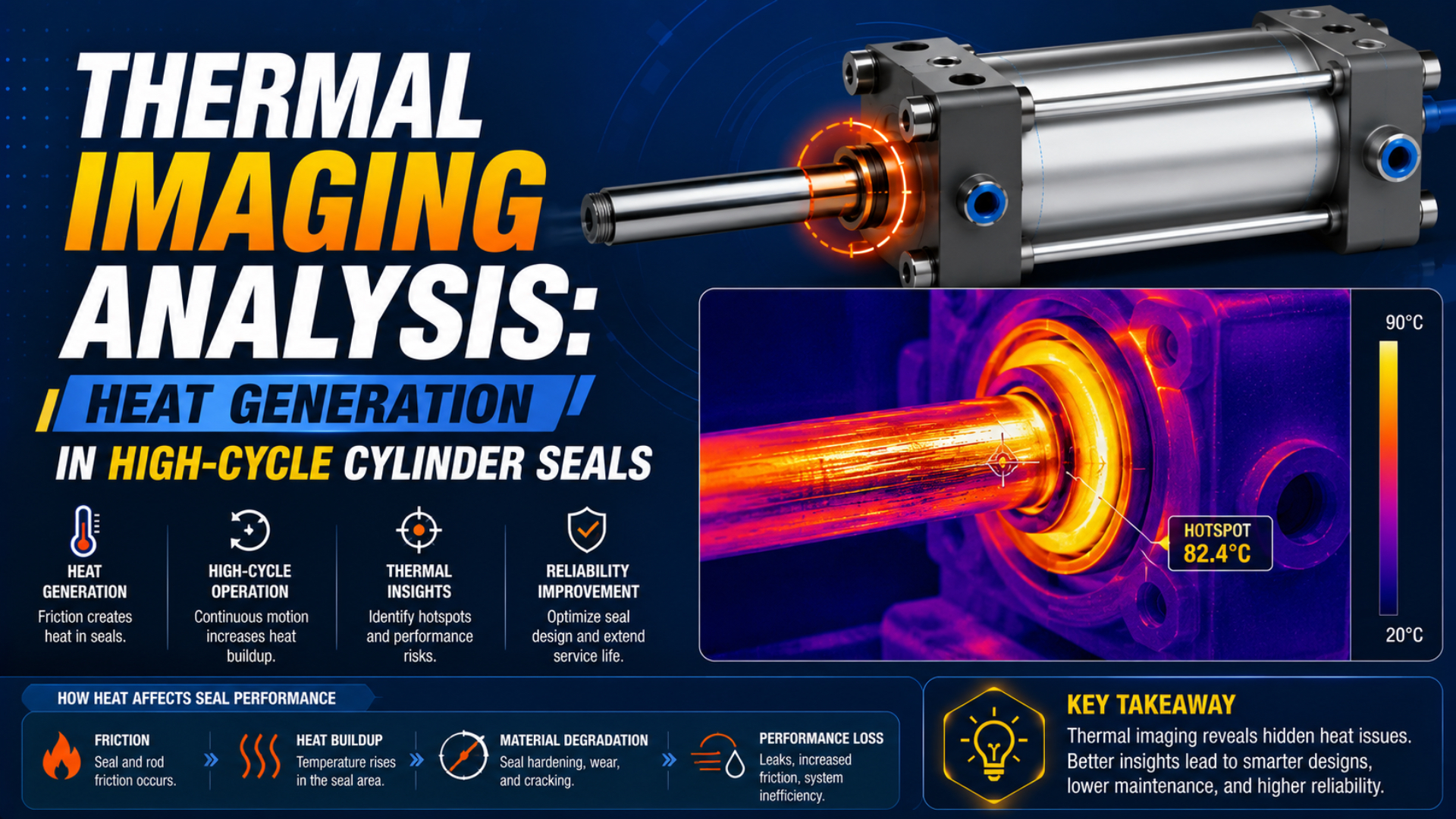
Thermal imaging analysis of cylinder seals is a controlled comparison of apparent surface temperature around a pneumatic actuator. It can locate a thermal anomaly without touching moving hardware, but it does not see through the gland, identify the seal compound, or prove why heat was generated. Useful inspections connect the thermal pattern with load, pressure, speed, alignment, leakage, surface condition, and a repeatable baseline.
High-cycle operation can produce heat through seal and bearing friction, gas compression, cushion losses, impact, and heat conducted from nearby machinery. Expansion and exhaust can create local cooling at the same time. The camera therefore shows the net surface response after heat generation, heat rejection, reflection, and instrument effects have all interacted.
Key Takeaways
- FLIR recommends at least a 3 × 3 pixel target for reliable spot measurement.
- A thermal image shows apparent surface temperature, not internal seal temperature.
- Compare identical operating states before treating a hot region as a fault.
- Confirm every anomaly with mechanical, pneumatic, and contact-temperature evidence.
What Does a Thermal Camera Actually Measure at a Cylinder Seal?
ISO 18434-1 identifies at least 3 corrections for quantitative machine thermography: target emissivity, reflected apparent temperature, and attenuating media. A camera therefore estimates the surface temperature represented by received infrared radiation; it does not directly measure the elastomer inside the gland (ISO 18434-1, confirmed 2023).
The distinction matters because the hottest internal contact can be hidden by the head, bearing, seal cartridge, or barrel. Heat must conduct through those parts before appearing at the visible surface. Airflow, mounting brackets, guards, paint, and nearby hot equipment change that surface response. The hand-held image maps the accessible boundary, not a section view of the seal.
Use ambient-corrected surface temperature rise for comparison:
Here, is the surface rise above local ambient, is the corrected temperature at a named cylinder location, and is the nearby air temperature recorded at the same time. Use degrees Celsius or kelvin consistently. This relationship normalizes the environment; it does not calculate internal seal temperature. Define every measurement point before testing, including the rod gland or rodless sealing slot, each end cap, barrel mid-stroke, mounting bracket, valve body, speed controller, and exhaust device. Compare these points with the broader high-cycle cylinder thermal analysis method, which covers contact sensors and thermal time constants in more detail.
What changed: the machine, the surface, or the measurement?
How Is Heat Generated During High-Cycle Cylinder Operation?
One 2017 experiment on a 50 mm-bore pneumatic cylinder recorded a 23 K chamber-temperature rise during compression and a 17 K drop during expansion. The same actuator can therefore experience heating and cooling within one cycle; neither value is a universal seal-temperature allowance (Hassan et al., 2017).
Several mechanisms can contribute to the temperature map:
- Sliding friction. Rod seals, piston seals, guide rings, bearings, scrapers, and sealing bands resist motion. Heat depends on actual friction force, sliding distance, speed, lubrication, contact pressure, surface condition, and material pair.
- Gas compression and filling. Chamber gas can warm rapidly. Metal and elastomer respond more slowly.
- Expansion and exhaust. Gas may cool across chamber blowdown, valve restrictions, speed controllers, and silencers. A cold exhaust path can coexist with a warm gland, so scan the valve and exhaust hardware instead of assuming the gland contains the only thermal event.
- Elastic losses. Repeatedly deformed elastomers dissipate energy. Quantification needs compound-specific loss data and the real strain cycle.
- Impact and cushioning. End-of-stroke energy can become heat in cushion restrictions, bumpers, seals, end caps, external stops, and the moving machine. Measure actual impact speed and inspect the hard-stop condition before changing seal material.
- External transfer. Ovens, motors, hot product, and sunlight can warm the actuator independently.
Hot glands are the end of an energy path, not the beginning of a diagnosis. The same surface rise could result from greater friction, less airflow, heat conducted through a bracket, a changed cycle recipe, or a reflective target. Compare heating and cooldown curves. If operating temperature changes but cooldown does not, generation deserves priority. If both change, investigate heat rejection and the surrounding machine.
That ambiguity is the point.
Do not estimate surface temperature from an ideal adiabatic pressure-ratio equation. That model describes a gas-process boundary under stated assumptions, not the temperature of a hidden seal or visible housing. Use the separate guide to adiabatic expansion and cooling in pneumatic cylinders when the gas path itself needs analysis.
Why Do Polished Cylinder Surfaces Produce False Hot or Cold Spots?
FLIR states that polished stainless steel can have an emissivity around 0.14, compared with about 0.93 for structured PVC. Low-emissivity surfaces act more like infrared mirrors, so the camera can display radiation reflected from people, heaters, lights, or nearby machinery instead of the target’s own emission (FLIR).
This problem is common around chrome-plated rods, polished stainless components, anodized aluminium, bare fasteners, and oily surfaces. Adjacent paint, labels, seals, and metal finishes may have different emissivities while sitting at nearly the same true temperature. A dramatic color boundary can therefore be optical, not thermal.
Treat the camera and its manual as one measurement system:
- Record the camera, lens, and calibration status.
- Determine target emissivity with a documented method. Never assign one value to every material simply because they appear in the same frame; record the condition of paint, plating, oxidation, oil, labels, and reference treatments.
- Compensate for reflected apparent temperature when quantitative results matter.
- Keep distance, angle, focus, lens, range, and environmental conditions consistent. Save a visible-light image with each thermogram.
- Confirm the measured region is large enough for the instrument’s field of view. Reposition the camera rather than relying on digital zoom, and document the pixel coverage used for the reported maximum.
- Validate critical locations with a repeatable contact sensor.
FLIR recommends covering the hot target with at least 3 × 3 pixels for a more reliable spot measurement. Seeing a small gland on the display does not prove enough pixels fall entirely on that surface (FLIR distance-to-size guidance). Digital zoom enlarges the display but does not improve the optical measurement area. NETD creates another common mistake: it describes the detector’s ability to distinguish small temperature differences from temporal noise, not absolute temperature accuracy. A camera with a low NETD may produce a detailed pattern while the reported temperature remains biased by emissivity, reflections, focus, calibration, or spot-size error.
Move the camera. Does the hot spot move too?
A Six-Step Thermal Imaging Inspection Workflow
ISO 18434-1 covers 2 broad thermography uses for machinery: condition monitoring and performance assessment. It also requires documented procedures, interpretation, assessment criteria, and reporting. A cylinder survey should follow the same discipline: control the operating state, preserve settings, compare equivalent assets, and verify anomalies before assigning a cause (ISO 18434-1).
1. Define the question and acceptance boundary
Decide whether the survey is screening a cylinder bank, investigating one repeat failure, validating a design change, or establishing a new baseline. Record the exact cylinder model, bore, stroke, seal option, lubricant policy, load, mounting, pressure, speed, cycle rate, duty period, cushion setting, valve, tubing, and environment.
2. Establish repeatable measurement points
Mark the rod gland, each end cap, barrel, bracket, valve, speed controller, and exhaust device. Include one local ambient point away from direct discharge and radiant sources. Keep the camera position, distance, angle, focus, palette, range, emissivity method, and reflected-temperature correction consistent.
3. Capture the idle and known-good baselines
Record the machine at idle after thermal stabilization. Then compare cylinders of the same model performing the same load and recipe. A neighboring actuator is not a valid reference when its bore, stroke, pressure, mounting, airflow, load, or duty differs. Baseline quality controls every later alarm.
4. Run the production duty without hidden changes
Record local ambient temperature, surface map, cycle count, elapsed time, supply pressure, both port pressures if available, motion time, leakage, and load state on a common time base. Continue long enough to see whether temperature approaches a plateau, keeps rising, or changes after a specific event.
5. Verify each anomaly independently
Verify quantitative temperature at a safe accessible surface with a contact probe. Check alignment, side load, rod and bearing condition, seal leakage, lubricant history, exhaust restriction, cushion impact, mount conduction, guards, and airflow. The cylinder side-loading guide explains how to preserve clock-position wear evidence.
6. Change one factor and repeat
Correct one measured cause, then repeat the same recipe, camera setup, and logging period. A lower apparent temperature after changing camera angle is not a machine improvement. A defensible result is a repeatable thermal change accompanied by corrected pressure, motion, alignment, leakage, or component condition.
What Can a Thermal Pattern Reveal, and What Can It Not Prove?
One NIST metal-cutting thermography example reported an expanded uncertainty of 54.3°C, with emissivity and point-spread function as the largest contributors. That demanding experiment is not a cylinder-camera accuracy claim. It demonstrates why an attractive color image cannot substitute for an uncertainty review (NIST, 2013).
Let pattern shape prioritize the next check, not close the investigation:
| Thermal observation under a controlled duty | Inspect next | Competing explanation |
|---|---|---|
| One gland sector warmer than the rest | Alignment, guide load, rod runout, bearing wear, installed clock position | Reflection, mixed surface finish, nearby radiant source |
| Circumferential gland rise | Seal friction, pressure, lubrication, rod surface, gland clearance | Uniform heat conducted from the head or chamber |
| One end cap warmer near stroke completion | Cushion setting, impact speed, external stop, restriction, piston condition | External bracket or process heat at that end |
| Barrel rise with warm valve and tubing | Cycle duty, chamber gas, leakage, restriction, supply temperature | Enclosure airflow or common external source |
| Cold speed controller or muffler | Local expansion, back pressure, moisture, exhaust restriction | Air jet cooling the visible housing |
| Image changes when the camera moves | Emissivity, angle, focus, reflection, measurement spot | A real transient occurring at the same time |
Hot rings do not prove misalignment. Alignment faults tend to leave directional mechanical evidence: one-sided bearing polish, asymmetric rod or seal wear, changing friction through the stroke, guide conflict, or mount movement. Compare the thermal clock position with these marks before correcting geometry. Likewise, a uniform rise does not prove “seal degradation.” It may reflect normal stabilization at a higher ambient temperature or duty. Check leakage, breakaway behavior, running speed, pressure traces, noise, surface condition, and cooldown. The guide to dynamic versus static cylinder seals helps separate rod-end leakage, internal bypass, guide wear, and fixed-joint faults.
The pattern is a lead, not a verdict.
In our experience, the fastest way to destroy the value of a thermal survey is to change several conditions between images. Changing the palette, automatic range, angle, guard position, cycle rate, or surface condition can create a persuasive “improvement.” Freeze the measurement method before comparing colors or maximum values.
How Should Seal Temperature Limits and Thermal Aging Models Be Used?
ISO 11346:2023 defines 2 approaches for estimating rubber thermal endurance, Arrhenius and WLF, using changes in selected properties after elevated-temperature exposure. It also warns that different rubber properties age at different rates, so compounds can only be compared using the same property and test basis (ISO 11346:2023).
That boundary rules out a universal claim that every 10°C rise halves the service life of every cylinder seal. An Arrhenius fit requires compound-specific data, selected failure property, exposure duration, temperature range, and a justified extrapolation. Dynamic reciprocation adds friction, wear, pressure, media, lubricant, surface, and deformation that a thermal-aging curve alone does not represent. Parker explains that its high-temperature recommendations for compounds are based on approximately 1,000 hours of continuous service in typical compatible media. It also notes that the upper limit varies with the medium and that the seal and fluid limits must both be considered (Parker O-Ring Handbook). Generic NBR, FKM, PTFE, or polyurethane labels are therefore insufficient.
Which documented limit actually governs?
For an installed cylinder, obtain the complete model code and seal option. Confirm:
- assembly temperature range;
- dynamic rating for the exact seal profile and compound, including the stated medium and lubrication condition;
- lubricant identity, compatibility, and its separate temperature boundary;
- permissible speed, pressure, stroke, cycle duty, side load, and cushioning under the selected mounting arrangement;
- exposure to cleaning chemicals, process fluids, ozone, water, compressed-air contaminants, radiation, and outdoor weather;
- the manufacturer’s complete inspection, replacement, repair, test, and return-to-service instructions for that model code.
Consult the cylinder seal temperature and material-selection guide for compound-specific questions. Thermal imaging supplies field evidence. It does not replace the product rating or material qualification.
The full assembly sets the boundary.
Set two different thresholds. The first is a diagnostic trigger based on repeatable deviation from a qualified baseline. The second is a hard operating boundary from the exact component documentation. A baseline trigger tells maintenance to investigate. A product limit tells engineering whether operation is permitted. Neither should be invented from a generic color scale.
Corrective Actions and Return-to-Service Evidence
ISO 19973-3 expresses pneumatic-cylinder life in cycles or kilometres and evaluates reliability under declared test conditions. Thermal trends can support maintenance decisions, but they cannot convert one surface temperature into a remaining-life prediction without validated failure data for the exact cylinder and duty (ISO 19973-3, confirmed 2021).
Match the correction to verified evidence:
- Correct the verified alignment fault.
- Replace damaged seals, bearings, rods, wipers, or barrels only after checking the mating surface, measurement limits, and initiating cause. Keep removed parts in their installed orientation until the evidence is documented.
- Restore the model-approved lubricant policy. Never add arbitrary low-friction grease to a factory-greased or process-sensitive cylinder.
- Measure exhaust back pressure, correct flow-control installation, and verify cushion energy when heating coincides with a restriction or end impact. Recheck stroke time and machine stability after the change.
- Improve shields, cleaning, filtration, drainage, or air quality when contamination or corrosion is confirmed.
- Restore ventilation or isolate conducted and radiant heat when the cooldown path changed without a matching friction increase. Check the guard position, bracket contact, enclosure airflow, and nearby process temperatures before altering the cylinder.
If the rod or seal surface is damaged, follow the failure evidence path in boundary lubrication and cylinder rod scoring. Do not use a lower thermal reading to approve a rough rod, leaking pressure seal, damaged bearing, or unsafe mount. Return to service under the machine’s approved energy-control and commissioning procedure. Leak-test both directions, cycle slowly, confirm full travel and sensor operation, then restore the representative load. Record dynamic pressure, motion time, temperature map, ambient reference, camera settings, contact reading, leakage, cushion behavior, alignment, and the accepted configuration.
Correct the cause, then repeat the evidence.
Schedule an early repeat survey after the corrective action. The image should reproduce under the same duty and measurement method. More importantly, the associated functional evidence should improve. A cooler color palette alone is not acceptance.
High-Cycle Cylinder Seal Thermography FAQs
FLIR recommends at least a 3 × 3 pixel target for spot measurement, while ISO 18434-1 requires compensation for emissivity and reflected apparent temperature. These 5 answers keep thermography within those measurement limits and separate screening, diagnosis, material ratings, and inspection intervals (FLIR; ISO 18434-1).
Can a thermal camera measure the internal cylinder seal temperature?
Not directly. It estimates temperature at the visible radiating surface after emissivity, reflection, atmosphere, optics, and heat conduction have affected the signal. The hidden seal contact may be hotter, cooler, or responding faster. Validate critical locations with an approved contact method and use model-specific limits rather than an assumed offset.
Does a hot band around the rod gland prove misalignment?
No. Hot bands can result from friction, conducted heat, surface finish, reflection, pressure, lubricant condition, or restricted cooling. Misalignment becomes more credible when the thermal direction agrees with one-sided bearing or seal wear, rod runout, guide conflict, mount movement, and a repeatable change after mechanical correction.
What emissivity should I use for a chrome-plated cylinder rod?
Do not use one universal value. Emissivity depends on finish, oxidation, coating, contamination, wavelength, temperature, and viewing geometry. A polished rod can reflect nearby radiation strongly. Follow the camera maker’s method, use a safe approved high-emissivity reference when appropriate, and document reflected-temperature compensation and angle.
What temperature rise means a high-cycle seal is failing?
There is no universal rise that proves failure across cylinder models and compounds. Use a repeatable deviation from a qualified baseline as an investigation trigger, then compare the corrected surface and contact measurements with leakage, friction, pressure, alignment, damage, and the exact cylinder’s allowable operating range before taking action.
How often should pneumatic cylinders receive thermal imaging inspections?
Set frequency from machine criticality, failure consequence, duty, previous trend stability, and the plant’s condition-monitoring program. A new or recently corrected fault may justify short-interval checks; a stable low-risk asset may not. ISO 19973-3 test life does not provide a universal field inspection calendar, so document the risk basis.
Sources and technical references
- ISO 18434-1:2008, machinery thermography procedures, emissivity, reflected apparent temperature, interpretation, and reporting; confirmed 2023.
- FLIR, How Does Emissivity Affect Thermal Imaging?, low-emissivity reflective surfaces and reflected temperature; retrieved 2026-07-22.
- FLIR, Understanding Distance:Size Ratio, measurement spot size and 3 × 3 pixel guidance; retrieved 2026-07-22.
- NIST, Uncertainty of Temperature Measurements by Infrared Thermography, uncertainty contributors in a demanding metal-cutting example; published 2013.
- ISO 11346:2023, thermal-endurance estimation for vulcanized and thermoplastic rubber; published 2023.
- Parker O-Ring Handbook, ORD 5700, compound, medium, duration, lubricant, and temperature boundaries; retrieved 2026-07-22.
- ISO 19973-3:2015, reliability testing and reporting for pneumatic cylinders with piston rods; confirmed 2021.