

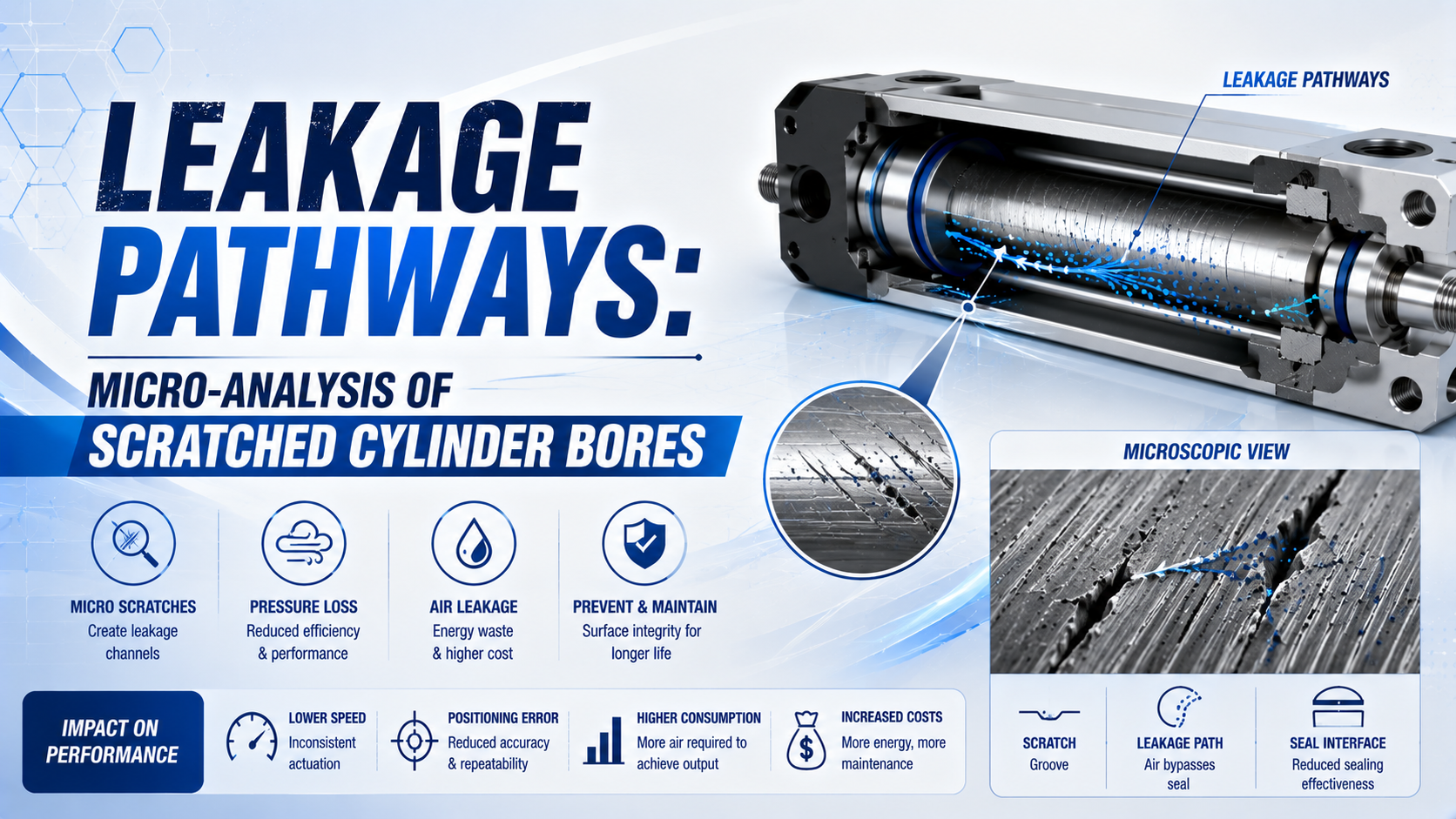
A scratch in a pneumatic cylinder bore becomes a leakage pathway only when it leaves a continuous, insufficiently sealed channel across the piston’s effective contact band. Scratch depth alone cannot tell you whether that channel exists or how many standard litres per minute it will pass.
The diagnosis must connect three kinds of evidence: where the air goes, whether leakage changes with piston position, and what the bore and seal actually look like. This prevents a valve leak, damaged end-cap seal, cut piston seal, or geometry error from being misreported as a scratched bore.
Key Takeaways
- Scratch depth alone cannot predict leakage.
- The defect must bridge the seal contact band.
- Pressure decay measures the complete isolated boundary, not one component.
- ISO 21920-2:2021 defines current profile parameters; inspect discrete scratches, bore geometry, coating, and seal damage separately (ISO).
What Turns a Bore Scratch Into a Leakage Path?
A 2025 elastomer-seal study used three experimental datasets to validate a leakage model and reported an average relative error below 10 percent. The model combined surface topography with non-uniform contact pressure instead of assigning leakage to groove depth alone (Industrial Lubrication and Tribology, 2025).
Seal contact band is the finite area where the piston seal presses against the bore and separates the two working chambers.
Leakage pathway is a connected, insufficiently sealed route from the high-pressure side of that band to the low-pressure side. A scratch matters when it helps form that route under the actual pressure, temperature, lubrication, speed, and deformation conditions.
This distinction changes how scratch geometry should be described:
| Observation | What it can indicate | What it cannot prove alone |
|---|---|---|
| Axial scratch along the piston travel | It may repeatedly cross the piston-seal contact band | A specific leak rate |
| Circumferential mark | Local wear, debris, or assembly damage | A continuous chamber-to-chamber path |
| Deep but isolated pit | Local coating or material loss | That high and low pressure are connected |
| Polished band on one side | Uneven contact, side load, or geometry error | That surface roughness was the original cause |
| Matching cut in the seal lip | The bore or trapped debris contacted the seal | That the bore is the only remaining leak source |
Rubber-seal leakage models require both microscopic surface topography and macroscopic contact pressure. Recent experimental work on elastomer sealing interfaces likewise shows that material properties and local contact pressure can strongly change leakage near the point where a connected channel forms (Xu et al., Tribology International, 2026). That is why assigning one fixed SCFM value to every scratch of a stated depth is not defensible.
Channel length also needs careful wording. For a given open cross-section and pressure difference, a longer gas-flow path generally creates more resistance, not less. The relevant distance is the route through the seal’s contact zone. A scratch can extend along much of the barrel while the pressure-connected section through the seal remains close to the contact-band width.
Multiple scratches do not automatically create exponential leakage. If separate open channels experience similar boundary conditions, their flows may approximately add. In a real dynamic seal, however, local deformation, lubrication, wear, and interacting surface features make even that approximation configuration-specific.
First Separate Bore Damage From Other Leakage Sources
For example, one SMC cylinder document specifies 10 cm3/min (ANR) internal leakage and 5 cm3/min external leakage for a C95SB160 actuator. This model-specific limit shows why a test must identify where the air travels before it can classify the fault (SMC CP80-TFR12, 2013).
A falling pressure reading does not identify a scratched bore. It shows that gas left the test volume or changed state. Before disassembly, separate the possible destinations:
- Chamber-to-chamber bypass: air crosses the piston sealing interface and reaches the opposite cylinder port.
- External cylinder leakage: air escapes at a rod seal, end cap, port, fitting, or sealing band.
- Circuit leakage: air crosses a directional-valve spool, check valve, regulator, tube connection, or test fixture. It can reproduce the same drift or pressure-loss symptom while the cylinder bore remains serviceable, so test the circuit separately before condemning or dismantling the barrel.
The distinction is especially important for rodless cylinders. A magnetically coupled rodless cylinder uses a closed tube and does not have the same external sealing-band path as a mechanically coupled slotted-tube design. On a slotted-tube cylinder, leakage at an inner or outer band is not automatically piston-seal bypass. Diagnose the actual construction before assigning the fault to the bore.
Compressed air is stored energy. Isolate motion hazards, support suspended loads, exhaust trapped energy, and follow the machine’s lockout procedure before disconnecting components. Any pressurized component test should use the cylinder manufacturer’s method, rated fixtures, and trained personnel.
A useful sequence is:
- Record the cylinder model, bore, stroke, seal kit, pressure, temperature, speed, load direction, lubrication policy, and exact symptom.
- Check fittings, tubing, ports, end caps, the rod gland, sealing bands, and valve exhausts for external leakage.
- Measure both cylinder-port pressures during the faulty motion or hold state. Regulator pressure alone does not describe the seal differential.
- Separate the valve and cylinder test boundaries using an approved procedure.
- Test in both directions and at several piston positions, including positions immediately before and after the suspected damaged region. Repeat any abrupt change so one unstable reading doesn’t become the diagnosis.
- Compare the result with a model-specific limit or a documented new-condition baseline. Keep the trace.
- Disassemble only after the operating evidence has been preserved.
Position sensitivity is useful but not conclusive. If leakage rises only when the piston seal crosses one location, local bore damage becomes more plausible. If the measured leak remains unchanged throughout the stroke, investigate the piston seal, end-cap seals, valve, fixture, and general bore geometry before focusing on one scratch.
For a broader separation of internal and external losses, use the pneumatic cylinder internal-leakage guide. It explains why valve state and test boundary matter before leakage is converted into an energy cost.
Pressure Decay Measures a Boundary, Not a Scratch
NASA’s pressure-decay validation records four essential quantities: known volume, absolute pressure, absolute temperature, and time. It also warns that a large volume combined with a small leak can extend a test for days, while a large leak in a small volume can leave too little data for low uncertainty (NASA, 2017).
Pressure data without a defined boundary is only a symptom.
Pressure decay can estimate the total gas lost from a known isolated volume. It cannot name the physical path without additional boundary tests.
For a constant-volume screening test, the normalized leakage estimate follows the ideal-gas relationship:
Q_N = V / delta_t
      x [(P_1,abs / T_1) - (P_2,abs / T_2)]
      x (T_N / P_N)
where V is the full isolated volume, P_1,abs and P_2,abs are absolute pressures, T_1 and T_2 are absolute gas temperatures, and P_N and T_N define the stated normal reference condition. Include the cylinder chamber, fittings, tubes, sensor cavities, and fixture dead volume.
For example, if temperature is stable, a 2.0 L isolated volume falling from 7.0 bar absolute to 6.9 bar absolute in 60 seconds gives a screening result of about 0.20 normal L/min when referenced near 1.013 bar absolute. This is a transparent calculation, not a claimed test result. It describes the whole boundary without saying whether the loss crossed a bore scratch, an end-cap O-ring, a tube fitting, or the isolation valve.
Pressure can change without leakage when compressed air cools after filling, ambient temperature shifts, a tube expands, a seal relaxes, or a fixture moves. Wait for equilibrium. Record temperature, verify the fixture with a reference or blank test, and use repeat measurements. A fixed percentage-over-time pass condition is meaningless without the volume, pressure, temperature behavior, sensor capability, and model-specific acceptance limit.
Direct flow measurement at the opposite cylinder port can be more diagnostic for piston bypass, provided the valve is excluded and the meter range and reference condition are suitable. Record whether the result is in ANR, NL/min, SLPM, SCFM, or actual volumetric flow. Never compare numbers that use different reference conditions as though they were identical.
Inspect the Bore Without Erasing the Failure Evidence
ISO 21920-2:2021 defines profile surface-texture parameters, while ISO 8785:1998 addresses discrete surface imperfections and was confirmed in 2025. The two-standard split supports a practical rule: don’t average a local scratch into a general Ra result and call the inspection complete (ISO 21920-2; ISO 8785).
Begin with the failed assembly in its received condition. Preserve the pattern. Mark the installed orientation, piston position, load direction, port locations, and clock position of each defect. Photograph the seal, wear rings, lubricant distribution, debris, polished bands, corrosion, and scratches before cleaning.
A clean image alone still cannot identify the flow path.
Then clean with the method permitted by the cylinder manufacturer. Do not use abrasive pads, metal picks, or improvised polishing to “see the scratch better.”
Those methods can change the evidence and create a new sealing defect. A fingernail, cotton swab, or spare seal lip cannot quantify micrometre-scale depth and may contaminate or damage a controlled surface.
Inspection should separate three layers:
| Inspection layer | Suitable evidence | Decision it supports |
|---|---|---|
| Local surface imperfection | Borescope or microscope image, location, orientation, length, width, profile across the feature | Whether a discrete scratch, pit, dent, or coating break exists |
| Surface texture | Ra plus the specified supporting parameters, trace direction, filters, evaluation length, instrument and calibration status | Whether the surrounding manufactured texture meets the drawing |
| Bore geometry and material system | Diameter at several stations and directions, taper, roundness or cylindricity, coating type and remaining condition | Whether the barrel can support the seal within dimensional limits |
ISO 21920-2:2021 defines current profile surface-texture terms and parameters, while ISO 21920-3:2021 defines the specification operator. ISO lists ISO 4287 and ISO 4288 as withdrawn predecessors (ISO 21920-2; ISO 21920-3). Surface imperfections have a separate vocabulary in ISO 8785:1998, which ISO confirmed in 2025 while a replacement remains under development.
That separation matters because Ra averages deviations over an evaluation length. Two bores can share the same Ra while one contains an isolated groove that crosses the seal track. Mitutoyo’s surface-roughness guide explicitly treats scratches, cracks, and dents as imperfections rather than normal roughness-profile content (Mitutoyo Quick Guide to Surface Roughness Measurement, accessed 2026).
When profiling a suspected scratch, place a trace across the feature to characterize its local profile, then measure the surrounding texture according to the drawing. Record the stylus-tip radius or optical method, access angle, filtering, uncertainty, and exact location. A trace along the bottom of a longitudinal scratch can miss its depth.
Do not let a good texture reading overrule a bad diameter or coating result. Geometry still wins. Taper, ovality, barrel shape, local deformation, coating breakthrough, and embedded abrasive can all change seal contact without producing a dramatic Ra value. The companion guide to Ra and Rz in cylinder barrels covers the measurement settings and inspection map in more detail.
The strongest bore-damage diagnosis is a location correlation: leakage changes as the piston crosses a recorded position, the bore shows a defect at that position and clock angle, and the seal or wear ring carries matching damage. None of those observations is as persuasive alone.
In our experience reviewing application data, a location map is usually more useful than a binary “scratched” label. It makes the operating symptom, bore feature, and damaged sealing component comparable on one record without pretending that appearance alone proves causation.
Repair or Replace the Barrel?
Festo’s DSBC repair instructions say the complete ISO cylinder must be replaced when the cylinder barrel is significantly damaged. That is a model-family instruction, not a universal pneumatic rule, but it demonstrates why a generic micrometre threshold cannot authorize honing across different barrel constructions (Festo DSBC Repair Instructions).
There is no universal scratch-depth table that decides between monitoring, honing, and replacement. The decision begins with the exact cylinder drawing, barrel material, surface treatment, finished-bore tolerance, available seal sizes, and manufacturer repair instructions.
SMC’s CY-series rodless-cylinder manual advises considering cylinder replacement when excessive scratches or damage are observed and recommends cylinder replacement for specific wear-related tube-contact failures (SMC CY Series Operation Manual, 2025). Festo’s DNCB instructions require trained repair personnel and state that damage to the cylinder barrel calls for repair of the complete cylinder rather than an improvised seal-only intervention (Festo DNCB Repair Instructions).
Use a decision record like this:
| Evidence | Rebuild may remain viable | Replacement or factory repair is safer |
|---|---|---|
| Defect | No prohibited scratch, pit, burr, or coating break after approved inspection | Defect crosses the seal track or exceeds the manufacturer’s limit |
| Bore size and form | All locations remain inside the released drawing | Cleanup would exceed diameter, taper, roundness, or cylindricity limits |
| Surface system | Approved finishing process preserves the required layer | Honing would remove anodizing, plating, coating, or hardened material |
| Seal path | Correct kit, groove, squeeze, lubricant, and future spares remain controlled | Repair requires an undocumented oversize seal or altered groove |
| Root cause | Debris, assembly, guidance, or alignment cause has been corrected | Side load, worn guides, bent structure, or repeat damage remains unresolved |
| Verification | Model-specific leak and motion acceptance test is available | No traceable acceptance method or baseline exists |
Honing is a controlled stock-removal and geometry-correction process, not a generic scratch eraser. On anodized or coated aluminium, a visually smooth bare-metal track may have lost the hardness, corrosion resistance, and tribological behavior the seal was designed to run against. Even on steel, material removal can alter bore diameter, straightness, taper, and crosshatch.
Follow the barrel and seal manufacturer’s approved repair allowance. The separate cylinder-barrel honing guide explains why final geometry, coating integrity, cleaning, and functional testing must be verified together.
ISO 15552 does not supply a universal repair depth or bore-finish rule. Its scope is basic, mounting, and accessory dimensions needed for interchangeability of specified pneumatic cylinders (ISO 15552:2018, confirmed 2025). An ISO-compatible mounting envelope therefore does not make two internal barrel finishes, seal systems, or repair procedures equivalent.
Prevent Repeat Scoring by Tracing the Entry Path
ISO 8573-1 classifies compressed-air purity across three principal contaminant groups: particles, water, and oil. It does not prescribe one filter grade for every actuator, and it does not cover external grit entering through a rod interface or sealing band (ISO 8573-1:2010).
A replacement barrel can fail again if the damage mechanism remains in the machine. Divide contamination and loading evidence by entry path:
- Supply-air contamination: particles, condensate, corrosion products, pipe scale, seal fragments, or assembly debris entering through the ports.
- External contamination: dust, abrasive slurry, weld spatter, washdown chemicals, or chips reaching a piston rod, wiper, carriage, guide, or sealing band.
- Internal generated debris: a failing seal, wear ring, guide, coating, or misaligned piston creating particles inside the actuator. Match the debris to the worn component before replacing either part.
- Mechanical contact: side load, incorrect mounting, excessive moment, impact, or tube deformation.
- Assembly damage: burrs, dirty tools, forced seals, or incompatible lubricant.
Set the air-quality requirement from the exact actuator, process, environment, and downstream sensitivity. Then verify the delivered condition at the relevant point in the system.
Mechanical evidence deserves equal weight. SMC warns that misalignment between the piston rod and load can damage the cylinder tube, bushing, rod surface, and seals, and that tube-bore deformation can cause malfunction (SMC CS2 Series Operation Manual). One-sided polishing on the piston seal and wear ring should therefore trigger alignment, guide, moment, and mounting checks before a new barrel is installed.
Close the corrective-action loop with:
- retained failed parts and a location-based damage map;
- branch-point particle, water, oil, and drain results compared with the actuator requirement;
- flushed contaminated tubing;
- inspected port edges, clean assembly tools, and the approved lubricant;
- measured alignment;
- documented model-specific seal, pressure, speed, load, and lubrication settings;
- post-repair leakage and motion baselines;
- a follow-up inspection interval selected from duty, environment, failure consequence, and observed wear rather than a universal calendar rule.
If the failure investigation shows repeated seal damage without a stable material specification, compare the wear pattern with the material science of cylinder piston seals. Seal compound, hardness, profile, lubrication, temperature, and chemical exposure can change conformity and wear even when the bore is unchanged.
Build a Traceable Bore-Damage Report
NASA’s pressure-decay method derives gas mass from absolute pressure, temperature, and known volume at each time step. That measurement chain is a useful reporting model: preserve the inputs, boundary, conditions, and repeated observations so another engineer can reproduce the conclusion (NASA/TM-2008-215428, 2008).
A useful bore-damage report should include:
- cylinder manufacturer, complete model code, bore, stroke, serial or batch identity, and service hours or cycles if known;
- installed orientation, mounting, external guide, load, moment, speed, pressure at both ports, temperature, and valve state;
- leak-test boundary, included volume, sensor ranges, resolution, calibration status, reference conditions, stabilization time, fixture result, raw pressure and temperature traces, and repeated measurements;
- leakage versus piston position and direction;
- photographs keyed to axial position and clock angle;
- seal, wear-ring, wiper, end-cap, rod, sealing-band, and lubricant condition;
- bore diameter and form results at declared locations;
- surface-texture settings and separate defect measurements;
- barrel material, coating or anodizing specification, and remaining repair allowance;
- root-cause evidence, corrective action, and post-repair acceptance results.
This record supports a defensible supplier conversation. It also prevents a recurring failure from being reduced to “replace the seal again.” For an application review, send the cylinder model, drawings, failure map, measured leakage, operating conditions, and photos through the technical contact page. A replacement recommendation should follow the evidence, not precede it.
FAQs About Scratched Cylinder Bores
How deep must a cylinder-bore scratch be before it leaks?
There is no universal depth. Leakage depends on whether the defect creates a connected channel across the seal contact band, plus scratch profile, seal geometry, compound, contact pressure, lubrication, temperature, speed, wear, and bore form. Compare measured leakage and inspected damage with the exact cylinder and seal manufacturer’s limits.
Can pressure decay confirm that a bore scratch is leaking?
No. Pressure decay confirms a pressure or gas-mass change within the isolated test boundary. It cannot identify the path by itself. Exclude the valve and fixture, check external leakage, repeat at several piston positions, and correlate the result with bore and seal inspection.
Should a scratched aluminium cylinder barrel be honed?
Only when the manufacturer permits it and the finished barrel will retain the specified diameter, form, surface treatment, texture, and seal compatibility. Many aluminium barrels use anodized or engineered surfaces. Removing that layer can make a visually smooth repair functionally unacceptable.
Does a new piston seal that still leaks prove the bore is damaged?
No. The replacement seal may be cut, installed incorrectly, incompatible, or poorly lubricated. Leakage may also cross the valve, test fixture, end-cap seals, rod seal, sealing band, or an out-of-round bore. Preserve the operating evidence and isolate each boundary before assigning the cause.
Are rodless cylinders more vulnerable to scratched bores?
Not as a universal rule. Mechanically coupled slotted-tube and magnetically coupled sealed-tube rodless cylinders use different sealing architectures and contamination paths. Risk depends on construction, guidance, environment, loading, maintenance, and protection. Diagnose the exact cylinder series rather than treating every rodless cylinder as an exposed bore.
Sources and Technical References
- ISO 21920-2:2021, Surface texture: Profile - Terms, definitions and surface texture parameters, current profile-parameter framework; retrieved 2026-07-23.
- ISO 21920-3:2021, Surface texture: Profile - Specification operators, rules defining the complete profile-surface specification operator; retrieved 2026-07-23.
- ISO 8785:1998, Surface imperfections - Terms, definitions and parameters, vocabulary for scratches and other discrete imperfections; confirmed 2025.
- ISO 8573-1:2010, Compressed air - Contaminants and purity classes, particles, water, and oil purity classification; retrieved 2026-07-23.
- ISO 15552:2018, Pneumatic cylinders - Basic, mounting and accessory dimensions, interchangeability scope; confirmed 2025.
- SMC CY Series Operation Manual, CYxR-OM0001H, troubleshooting guidance for seal damage, foreign matter, excessive scratches, and tube contact; 2025.
- SMC CS2 Series Operation Manual, CS2-OM0237Q, alignment, tube protection, contamination, and post-repair leak inspection guidance.
- Festo DNCB Repair Instructions, 7DNCB_EN, model-specific training, documentation, and barrel-damage repair requirements.
- Festo DSBC Repair Instructions, 7DSBC_EN, replacement instruction for significantly damaged cylinder barrels.
- Mitutoyo, Quick Guide to Surface Roughness Measurement, profile direction and separate treatment of scratches, cracks, and dents; retrieved 2026-07-23.
- NASA, Validation of Test Methods for Air Leak Rate Verification of Spaceflight Hardware, pressure-decay volume, temperature, duration, and uncertainty considerations; 2017.
- NASA/TM-2008-215428, Leakage Quantification of Elastomer Seals, ideal-gas mass calculation from pressure, volume, temperature, and time; 2008.
- SMC CP80-TFR12, model-specific internal and external leakage limits for one C95SB160 actuator; 2013.
- A leakage rate calculation method for rubber O-ring seals, combined macro- and micro-scale leakage model validated against three experimental datasets; 2025.
- Xu et al., Leakage at interfaces based on Persson contact mechanics theory, experimental and theoretical evidence for surface-topography, modulus, and contact-pressure effects; 2026.