

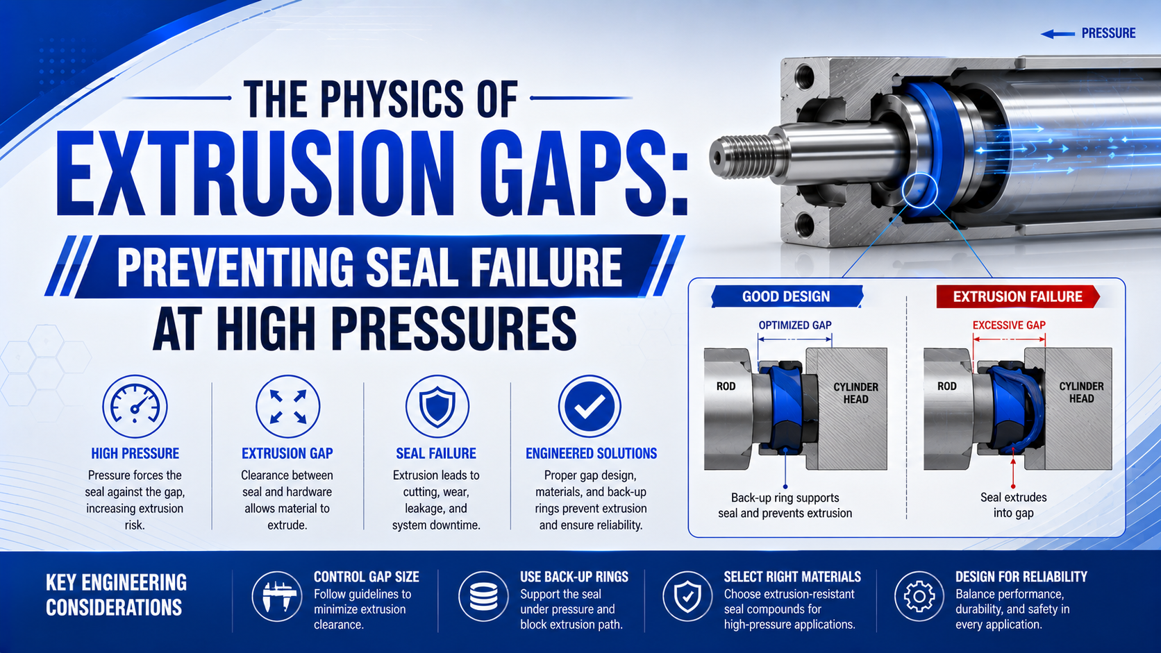
An extrusion gap is the clearance beside a pressurized seal into which the sealing material can be forced. Preventing failure isn’t a matter of choosing the hardest available seal. The hardware, seal profile, compound, pressure direction, temperature, motion, wear, and pressure peaks must be evaluated as one sealing system.
The practical design question is therefore not, “What gap is safe at 10 bar?” It is, “What is the largest local gap this exact seal will see in the hottest, most worn, most eccentric pressure state, and does its manufacturer approve that condition?” That shift prevents false precision.
Key Takeaways
- Calculate both diametral clearance and the maximum local radial gap.
- Use the selected seal manufacturer’s pressure-gap-material data, not a Shore-hardness shortcut.
- Put a single backup ring on the low-pressure side; reversing pressure normally requires support on both sides.
- Diagnose nibbling separately from installation cuts, abrasion, chemical attack, and guidance wear.
What Is an Extrusion Gap in a Pneumatic Cylinder?
Trelleborg defines the relevant hardware clearance as radial clearance and states that permissible clearance depends on 3 inputs: system pressure, O-ring cross-section, and O-ring hardness. Extrusion gap is the open path beside the seal, not the groove depth or the seal’s installed squeeze (Trelleborg O-Rings and Back-up Rings, 2024).
In a piston seal, the gap usually lies between the piston or guide component and the cylinder bore. In a rod seal, it lies between the rod and gland hardware. An end-cap O-ring can also face a clearance path if pressure can separate or deform the mating parts.
Pressure energizes an elastomeric seal by moving it toward the lower-pressure side of its groove. That movement helps close the intended leakage path. If the supporting hardware ends before the seal material does, pressure can also push the material into the clearance. Repeated pressurization can then pinch, nibble, or tear the protruding edge.
This principle applies to O-rings, but the exact allowable gap does not transfer automatically to U-cups, compact piston seals, rod seals, or rodless-cylinder sealing bands. Each profile has its own geometry and support. For a broader map of those functions, see industrial cylinder seal types and dynamic versus static cylinder seals.
Calculating the Worst-Case Local Gap
Parker says a piston seal must be checked against the clearance between the piston and the expanded cylinder. For concentric circular parts, radial clearance is one-half of diametral clearance, so a 0.30 mm diameter difference produces a 0.15 mm radial gap before eccentricity is added (Parker O-Ring Handbook, 2025).
Start with the diameters at their worst permitted sizes:
Here, is the radial clearance with centered parts, is the maximum bore diameter, and is the minimum supporting piston, gland, or guide diameter. All dimensions must refer to the same temperature and pressure state.
Real hardware doesn’t remain perfectly concentric. Bearing clearance, side load, straightness, runout, and assembly alignment can shift the moving member toward one side, enlarging the local gap on the opposite side:
The term is the maximum credible center offset after the relevant geometric tolerances and guidance clearances are combined. Don’t add every drawing tolerance blindly. Use the assembly datum scheme and determine which contributors can occur in the same direction.
The useful drawing requirement is a local radial-gap limit at the seal, not an isolated IT grade. An IT grade describes tolerance width for a nominal size, but it doesn’t state the mating tolerance zones, assembled eccentricity, pressure expansion, or whether a quoted clearance is radial or diametral. Those missing details can double the apparent answer.
A worked tolerance-stack example
Suppose a bore can reach 50.20 mm, its supporting piston can fall to 49.90 mm, and the assembly can develop 0.04 mm of center offset. The concentric radial clearance is . The maximum local gap becomes .
That number is not automatically safe or unsafe. It is the hardware input to compare with the exact seal supplier’s curve or application limit. The example also shows why a drawing that lists only “0.30 mm clearance” is ambiguous.
Why Is There No Universal Pressure-to-Gap Table?
Parker limits one published 90-durometer clearance curve to its N1444-90 nitrile backup ring and temperatures up to 74°C. That boundary alone shows why a generic table cannot convert pressure and Shore hardness into one safe gap for every compound, cross-section, profile, speed, and duty cycle (Parker O-Ring Handbook, 2025).
Hardness matters because it affects deformation, yet it is only one material descriptor. Tensile strength, modulus, elongation, tear resistance, temperature, aging, media exposure, and the time history of pressure also change extrusion resistance. Shore A and Shore D values aren’t interchangeable, and two 90 Shore A compounds need not behave alike.
Cross-section matters too. Trelleborg’s permissible-clearance tables are organized by pressure, O-ring cross-section, and hardness, and the catalog explicitly excludes polyurethane and FEP/PFA-encapsulated O-rings from those elastomer tables. Applying one row to a polyurethane U-cup or PTFE-energized seal would ignore the manufacturer’s stated scope.
Use this decision order:
- Identify the exact seal profile, size, compound, and supplier.
- Determine whether the interface is static, reciprocating, rotating, or oscillating.
- Calculate the maximum local radial gap in the operating state.
- Check continuous pressure, peaks, dwell time, cycling, temperature, speed, and media.
- Compare that complete condition with the supplier’s current design data.
- Ask the supplier to approve conditions outside the published envelope in writing.
If pressure units differ across drawings and catalogs, convert them with the Pressure Converter, then keep the original and converted units together in the review record. Unit conversion can prevent a transcription error, but it cannot establish an allowable extrusion gap.
Backup Ring Placement Follows Pressure Direction
Parker gives 2 clear rules: if only one backup ring is used, the O-ring sits between that ring and the pressure source; for a double-acting assembly, a backup ring is required on both sides. In other words, the ring supports the seal at the low-pressure extrusion gap (Parker O-Ring Handbook, 2025).
A backup ring is a supporting element, not a second pressure seal. Trelleborg describes it as a part made from extrusion-resistant material. Its tight fit closes or reduces the clearance presented to the elastomer, allowing the pressure seal to retain its intended shape more effectively.
For a one-direction pressure source, place the backup ring on the side away from that source. If pressure can reverse, the low-pressure side reverses too, so support is normally required on both sides. This is common in double-acting circuits, but the groove and seal set must still match the selected product’s installation drawing.
Ring material and form also matter. PTFE, filled PTFE, hard elastomer, and engineering thermoplastic rings have different elasticity, thermal behavior, wear response, cut styles, and installation limits. A scarf-cut ring may install into a closed groove more easily, while a continuous ring avoids a cut interface. Neither choice excuses an oversized or sharply edged hardware gap.
Before assembly, record:
- pressure direction or both possible directions;
- ring quantity, material, profile, and part number;
- which face, if profiled, contacts the seal;
- groove width and axial freedom from the supplier drawing;
- lead-in chamfers and protected edges;
- final orientation after the gland or piston is assembled.
How Do Temperature, Pressure Expansion, and Wear Change the Gap?
Parker’s clearance guidance explicitly refers to the piston-to-cylinder gap after the cylinder has expanded under pressure, not just the room-temperature inspection size. A 2-part tolerance check therefore needs at least cold and operating-state dimensions, with pressure deformation added when the housing is compliant (Parker O-Ring Handbook, 2025).
For a first-pass thermal estimate, calculate each relevant diameter separately:
Here, is the diameter at operating temperature, is the measured or specified diameter at reference temperature , and is that component’s coefficient of thermal expansion. Apply the equation to both mating parts. The change in gap comes from their differential growth, not from adding barrel growth alone.
Pressure can enlarge a thin cylinder tube, while side load and guide wear can increase eccentricity. Coatings can wear, polymer guide elements can creep, and contamination can abrade support surfaces. These changes belong in the end-of-life stack when the application needs a defined maintenance interval.
Treat the gap as a set of operating states:
| State | Dimensions and effects to include | Review purpose |
|---|---|---|
| Cold assembly | measured bore, support diameter, initial eccentricity | confirm build and installation |
| Hot steady operation | differential thermal growth, pressure expansion, sustained load | check normal production |
| Transient peak | pressure spike, temperature excursion, rapid reversal | check short-duration risk |
| End of service interval | permitted wear, guide clearance, coating loss | set inspection or replacement criteria |
How Can You Distinguish Extrusion From Other Seal Damage?
Trelleborg specifies a 15° to 20° lead-in chamfer and rounded, polished entry edges for O-ring installation. That detail matters during diagnosis: a clean cut created once at assembly points toward an entry-edge problem, while repeated nibbling at the low-pressure clearance edge supports an extrusion mechanism (Trelleborg O-Rings and Back-up Rings, 2024).
Don’t diagnose from leakage alone. Remove the seal carefully, preserve its orientation, mark the pressure side, and photograph the groove before cleaning. Then correlate the damage location with the direction of pressure and the measured hardware gap.
| Observed evidence | More likely mechanism | What to verify next |
|---|---|---|
| Small bites or a ragged edge beside the low-pressure gap | extrusion or nibbling | local radial gap, peaks, backup-ring location, temperature |
| One clean slice or shaved edge near an entry path | installation damage | chamfer, burrs, assembly tool, edge protection |
| Dull, rough, uniformly scratched sliding face | abrasive contamination | air treatment, wiper, mating-surface contamination |
| Damage concentrated on one side of the circumference | misalignment or inadequate guidance | bearing clearance, side load, rod or carriage alignment |
| Swelling, softening, cracking, or unusual tackiness | media or chemical incompatibility | lubricant, cleaning agent, seal compound, exposure time |
| Polished wear with rising breakaway friction | lubrication or surface issue | surface finish, grease compatibility, dry-air duty |
One-sided damage deserves special attention. Enlarging the nominal diameter tolerance may not solve it if a worn bearing lets the piston, rod, or carriage shift under load. Review the role of rod bearings in seal protection before blaming the seal alone.
Surface texture can produce a different signature from extrusion. Directional scratches, coating damage, and excessive roughness affect lubricant retention and lip wear across the stroke. The cylinder barrel surface-finish guide explains why a single Ra value doesn’t describe every damaging feature.
What Should a Design Review or RFQ Specify?
Parker’s online O-Ring Selector checks both dimensions and tolerances rather than accepting one nominal gap value. A build-ready request should likewise distinguish 2 quantities: diametral clearance for manufacturing and maximum local radial gap for seal validation (Parker O-Ring Selector, accessed 2026).
State the seal system first:
- seal profile, cross-section, compound, hardness scale, and supplier part number;
- static, reciprocating, rotary, or oscillating motion;
- pressure direction, continuous pressure, peak pressure, and dwell;
- operating and start-up temperature range;
- medium, lubricant, cleaning chemicals, and contamination level;
- speed, stroke frequency, side load, and expected pressure reversals.
Then define the hardware evidence:
- mating diameters with limits, datum scheme, roundness, runout, and straightness;
- maximum local radial gap at the seal in cold, hot, pressurized, and worn states;
- groove dimensions, corner radii, entry chamfers, and relevant surface-finish parameters;
- guide or bearing clearances that contribute to eccentricity;
- backup-ring material, form, quantity, orientation, and drawing reference;
- inspection method, sampling plan, and acceptance record.
Ask whether the supplier’s published limit applies to the exact compound and profile. A statement such as “90 Shore A seal suitable for high pressure” is incomplete. The response should identify the approved gap, temperature, motion type, pressure duration, expected peaks, and whether a backup ring is included.
For custom cylinders, include a marked cross-section showing the pressure source and the gap being controlled. This small step catches reversed backup rings and radial-versus-diametral ambiguity before machining begins. It also makes later failure analysis much faster because the damaged edge can be mapped back to the drawing.
FAQs About Pneumatic Seal Extrusion
Parker recommends 2 backup rings for double-acting sealing assemblies and places a single ring opposite the pressure source. These FAQs apply that directional rule to gap calculations, harder compounds, worn hardware, and RFQ data without turning a model-specific pressure-clearance curve into a universal pneumatic limit (Parker O-Ring Handbook, 2025).
Can a universal safe extrusion gap be calculated from Shore hardness and pressure?
No. Hardness and pressure are inputs, but safe clearance also depends on seal profile, cross-section, compound, temperature, motion, dwell, pressure peaks, media, and backup support. Calculate the actual worst-case local gap, then compare it with the selected manufacturer’s data for that exact seal. Don’t reuse an O-ring table for a U-cup or PTFE seal.
Which side receives a single backup ring?
Install it at the low-pressure extrusion side, so the pressure seal sits between the ring and the pressure source. Pressure pushes the seal toward that supported clearance. Confirm the final orientation on the assembly drawing because gland installation can reverse what appears to be left and right when individual parts are on the bench.
What changes when pressure reverses?
The low-pressure side changes whenever pressure direction changes. Parker therefore calls for backup rings on both sides of an O-ring in double-acting service. For lip seals or compact piston seals, use the manufacturer’s double-acting arrangement rather than improvising two rings around a profile whose groove wasn’t designed for them.
Can a harder seal compensate for worn cylinder hardware?
Not reliably. A harder compound may resist deformation better, but it can also change friction, low-pressure sealing, wear, and surface conformity. Measure the worn bore, piston, gland, guides, and eccentricity first. If the local gap exceeds the selected seal system’s approved envelope, repair or replace the supporting hardware instead of treating hardness as a spacer.
What extrusion-gap data belongs in a cylinder RFQ?
Provide the seal part and compound, pressure direction, continuous and peak pressure, temperature, speed, media, diameters with limits, local radial gap, eccentricity, wear allowance, groove drawing, surface finish, and backup-ring arrangement. State whether dimensions are cold, hot, pressurized, new, or end-of-interval, and request the supplier’s written application limit.