

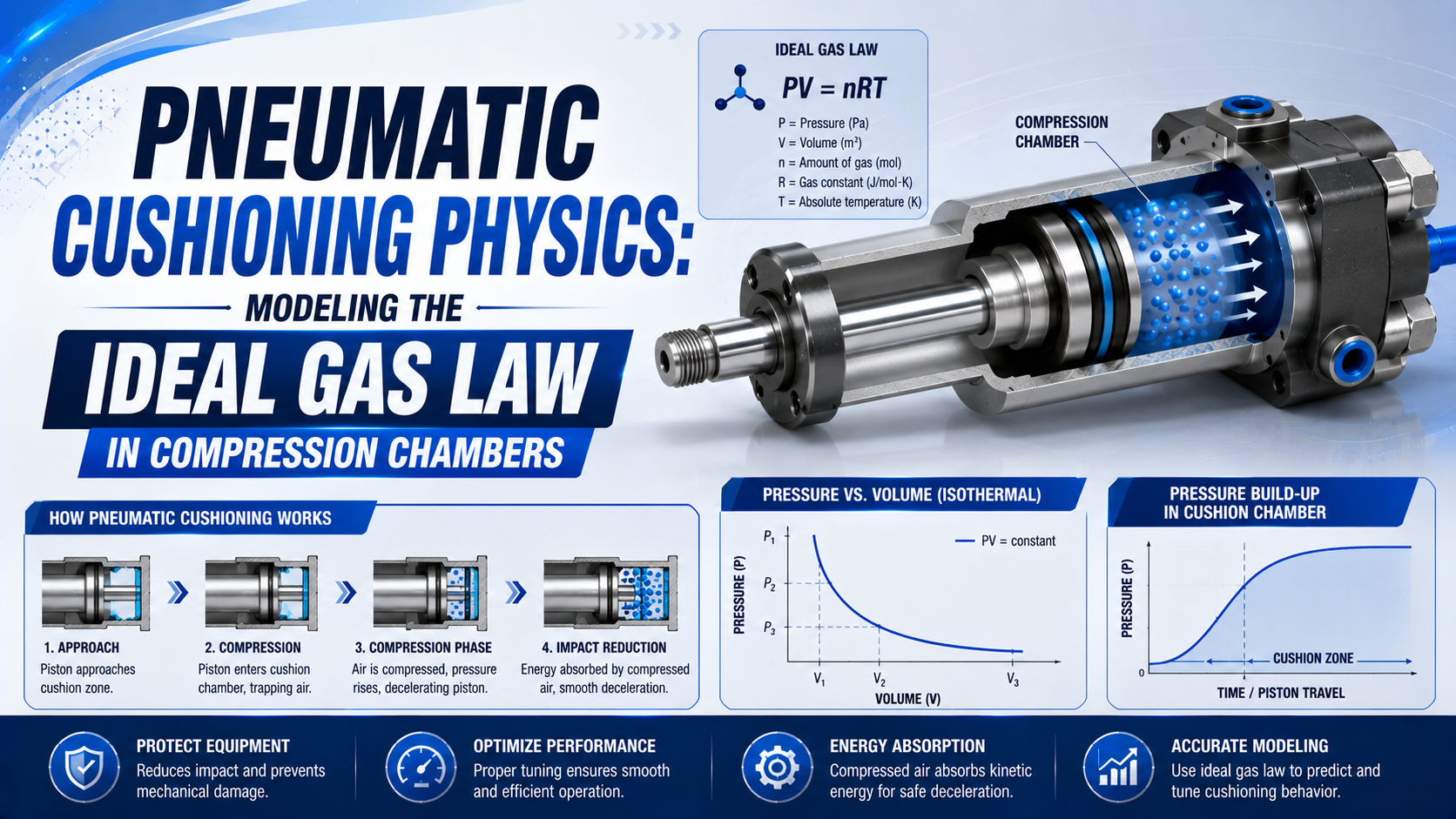
Pneumatic cushioning physics starts with the ideal gas law, which describes the air state inside the end chamber. It doesn’t predict the complete stop by itself.
Once the cushion sleeve closes the main exhaust path, chamber volume falls while air continues leaving through the adjustable needle. Pressure then depends on changing volume, gas mass, temperature, restriction flow, piston motion, friction, and the pressure in the opposite cylinder chamber.
A closed-mass relation such as can still provide a useful screening case over an interval where outflow and leakage are negligible. It must use absolute pressure, include clearance and connected dead volume, and remain separate from the cylinder manufacturer’s cushion-energy limit.
Key Takeaways
- The ideal-gas state equation is ; is a process approximation with additional assumptions.
- An adjustable cushion chamber normally remains an open system because air leaves through the cushion needle.
- Gauge pressure cannot be used directly in gas-law pressure ratios.
- Peak chamber pressure is not the same as net stopping force or allowable cushion energy.
- Final selection still requires the exact cylinder’s mass-speed curve, energy rating, pressure limit, and a commissioning test at the intended load, speed, pressure, orientation, temperature, and cycle rate.
For the general operating sequence and adjustment symptoms, use the pneumatic air cushioning guide. This article addresses a narrower engineering question: which thermodynamic model belongs inside the compression chamber, and what evidence is needed before trusting its result?
Why Is the Ideal Gas Law Only One Part of the Cushion Model?
NASA defines an ideal-gas state by pressure, volume, gas quantity, and absolute temperature. Written with gas mass, the equation is (NASA Glenn):
In this equation, is absolute pressure, is gas volume, is gas mass, is the specific gas constant, and is absolute temperature. These variables define an instantaneous state.
Nothing in the equation specifies how much gas crosses the cushion needle, how quickly the walls absorb heat, or how the piston accelerates.
Engineers also use the relation
It describes a selected polytropic path for an approximately fixed gas mass. Over the declared interval, the exponent represents the combined effect of work and heat transfer.
That exponent isn’t a permanent cylinder property or a substitute for the ideal-gas equation.
For two states on the same fixed-mass path:
This relation can be useful when both ports are blocked, leakage is negligible, and a trapped chamber is compressed over a known volume range. A working adjustable cushion is different: the main exhaust path closes, but a smaller path remains open through the cushion throttle. The air mass inside the end chamber therefore changes during deceleration.
Readers who need to fit can use the broader guide to polytropic processes in pneumatic cylinders. For a cushion calculation, first prove that a defensible closed-mass interval exists.
“Trapped air” describes restricted escape, not necessarily zero mass flow. Treating those phrases as equivalent produces unrealistic cushion-pressure calculations.
What Changes When the Cushion Sleeve Closes the Main Exhaust?
Parker describes an adjustable cushion in which a check seal closes the normal exhaust route and forces exhaust through an adjustable needle orifice. Festo similarly describes adjustable pneumatic cushioning as a defined end-chamber air volume whose outflow is controlled by an adjustment screw (Parker; Festo).
That mechanism creates three different flow states:
- Free exhaust: air leaves through the normal route.
- Transition: the cushion sleeve enters its matching seal; the main exhaust area collapses while piston motion continues.
- Needle-controlled compression: the end volume keeps shrinking, pressure rises, and the remaining air exits through a smaller adjustable passage whose conductance depends on the actual needle geometry.
After engagement, the cushion needle controls outflow. It doesn’t make gas mass constant or define the engagement position, piston area, remaining clearance, or maximum acceptable energy.
Counting turns cannot transfer a needle setting between cylinder series. Thread pitch, seat geometry, maximum travel, cushion-seal design, and downstream conductance differ.
The cushion-needle orifice guide covers subsonic and choked exhaust flow without treating turns as a universal flow unit.
Model Levels for Pneumatic Cushion Decisions
Parker warns that piston speed at cushion entry is typically about 50% higher than average stroke speed and uses that entry speed with moving mass for product selection. This makes the catalog envelope the first model level; more detailed thermodynamics should answer questions that the catalog cannot (Parker P1F-T catalog).
Model complexity should follow the decision while retaining the physics that can change it.
| Engineering decision | Minimum defensible model | Required inputs | What it cannot prove |
|---|---|---|---|
| Select a cylinder from a catalog | Manufacturer mass-speed curve or cushion-energy limit | Total moving mass, cushion-entry speed, direction, pressure, orientation, cycle rate | Actual pressure peak or rebound |
| Screen a nearly trapped interval | Closed-mass polytropic approximation | Absolute pressure, total volume, assumed or fitted , leakage boundary | Needle-flow transient or exact force history |
| Predict pressure and deceleration | Transient mass, energy, flow, and motion model | Throttle characteristic, dead volume, temperature model, friction, both chamber pressures, load | Safety without experimental validation |
| Diagnose an installed machine | Synchronized measurement plus catalog check | Pressure, position, time, valve command, load, supply and exhaust conditions | Unmeasured structural stress or hidden contact force |
That catalog method is the proper first gate because it comes from the selected product’s geometry and validation. A generic gas-law calculation does not know the cushion seal, throttle, end-cap strength, or rated energy.
If the operating point is outside the published envelope, adjusting the needle does not create more certified absorption capacity. Reduce cushion-entry speed, reduce moving mass, select a cylinder with adequate capacity, or add a correctly sized external stopping device.
Calculating Total Cushion-Chamber Volume
Nazarov and Weber’s validated cylinder model treats the end-cushioning volume as a physical control volume connected to its own throttle path. That boundary makes clearance, passages, and sensor cavities part of the gas volume rather than negligible geometric details (SICFP 2021).
A pneumatic cushion chamber is the complete end-volume on the selected side of the active restriction. The modeled volume must include every cavity inside that pressure boundary. A useful geometric form is:
is total cushion-side gas volume, is dead volume, is effective chamber area, and is the remaining piston travel measured from the selected end reference. Dead volume can include:
- end-cover clearance;
- the cushion recess and seal cavity;
- port drilling and internal passages;
- a pressure-transducer passage;
- fittings, a manifold branch, and any tubing that remains connected on the chamber side after the main exhaust route changes.
Ignoring dead volume makes the calculated compression ratio grow unrealistically as the piston approaches the end. It can also create an apparent singularity even though the real chamber never reaches zero volume.
Consider a deliberately closed screening example.
A chamber begins at 5.0 bar absolute and 40 cm³, then compresses to 20 cm³. Assume an illustrative exponent of :
Suppose the geometric swept volumes were 30 cm³ and 10 cm³. Adding 10 cm³ of dead volume to both states produces the actual values used above.
Omitting that dead volume would incorrectly use a 3:1 ratio instead of the correct 2:1 ratio and predict about 20.9 bar absolute. The volume boundary causes that difference; cushion performance didn’t improve.
For this guide, we analyzed the same end state with and without the 10 cm³ dead volume. Omitting it raised the predicted pressure from 12.3 to about 20.9 bar absolute.
We tested sensitivity to the pressure reference as well.
These are numerical boundary checks, not cylinder test data or product ratings. We found that an incorrect boundary can dominate the selected exponent.
This example isn’t a design pressure and doesn’t predict a real adjustable cushion. It assumes fixed gas mass and one exponent.
In working hardware, needle outflow changes gas mass while heat transfer and spatial temperature gradients alter the path.
Why Must Cushion Calculations Use Absolute Pressure and Temperature?
Gas-law ratios need a true zero reference. NIST defines one standard atmosphere as exactly 101,325 Pa, but local atmospheric pressure varies with weather and elevation (NIST).
For a local atmospheric pressure :
A gauge reading of 4.0 bar is therefore about 5.0 bar absolute when local atmosphere is approximately 1.0 bar. Entering 4.0 instead of 5.0 into a compression ratio understates every calculated absolute pressure by 20% in that example.
Temperature ratios likewise require kelvins. For a fixed-mass polytropic path:
This equation predicts an idealized bulk-gas endpoint.
It does not directly predict barrel, seal, end-cap, or exhaust-silencer temperature. Short cushion events also create spatial gradients that a single temperature value cannot fully represent.
In 2022, TU Dresden modeled cushion volume inside a multidomain cylinder simulation. Researchers compared calculated pressure, temperature, and piston motion with measurements at different supply pressures, piston speeds, and throttle openings.
Heat exchange was necessary to calculate cushion pressure and deceleration. Measuring temperature remained difficult during the fast, nonuniform event (Nazarov and Weber, 2022).
Open-System Cushion Modeling
A 2021 TU Dresden study measured the integrated cushion throttle’s flow characteristic. Its coupled model was validated with cushion pressure, temperature, and piston displacement at different throttle openings.
That evidence supports an open-system treatment whenever air continues leaving the shrinking end chamber (Nazarov and Weber).
An open-system cushion model tracks gas crossing the control boundary as well as the gas that remains inside it. Chamber mass becomes a state variable once air passes through the needle.
For a cushion chamber with no inlet during the modeled deceleration interval:
Ideal-gas state still follows:
A lumped energy balance can be written as:
is specific internal energy, is heat entering the gas, and is the specific enthalpy carried out through the restriction. As the piston enters the cushion, is negative, so compression work adds energy to the remaining gas. At the same time, escaping air removes mass and enthalpy.
Two limiting cases provide a useful sanity check. If needle outflow is negligible during a short interval, the chamber approaches a closed compression path and pressure rises rapidly as volume disappears. If the restriction passes air fast enough to offset the volume reduction, gas mass falls and pressure may rise slowly or remain near its initial level. A real adjustable cushion operates between those limits, and its trajectory can move during the same stop as upstream pressure, temperature, density, and effective needle conductance change. Neither limit is a product rating. They are boundary tests: a simulation that cannot approach both behaviors when its outflow parameter is varied probably contains an incorrect sign, volume definition, or flow connection. Run this check before trusting a predicted pressure or temperature peak.
Outflow requires upstream and downstream pressure, absolute temperature, and an effective flow characteristic.
ISO 6358-1 defines steady-state flow testing for pneumatic components with fixed or variable paths.
It explicitly excludes energy-exchanging components such as cylinders and accumulators. Component data can support the restriction model; they don’t convert the whole moving cushion into a steady-state device (ISO 6358-1).
Nazarov and Weber’s 2021 end-cushioning model measured the integrated throttle’s flow characteristic and validated the assembled model with cushion pressure, temperature, and piston displacement at different throttle openings. That work shows why assumed needle area and a single gas exponent are weak substitutes for product-specific flow data (SICFP 2021).
From Chamber Pressure to Deceleration Force
Nazarov and Weber parametrized seal friction across relative pressures from 2 to 8 bar and piston speeds from 0 to 0.8 m/s before validating their end-cushioning model. The range belongs to their test hardware, but the method shows why chamber pressure alone cannot represent cylinder deceleration (SICFP 2021).
Pressure inside one chamber is not the cylinder’s net force. Choose one motion direction as positive and calculate both chamber contributions:
Motion follows:
and are the effective areas, and both pressure values must use the same reference. includes gravity, springs, process force, and other external forces with signs defined from the chosen axis.
During extension into a rod-end cushion, rising rod-end pressure normally opposes cap-end drive pressure.
Retraction reverses those chamber roles. The same peak cushion pressure can therefore coincide with very different net force depending on the other chamber, rod area, and load.
Mechanical contact creates another boundary. If the piston, carriage, or tooling reaches a hard stop while residual velocity remains, structural contact force is not obtained from chamber pressure alone. It depends on contact stiffness, damping, clearances, mount flexibility, sampling bandwidth, and the effective moving mass. The end-of-stroke force guide separates average stopping force from peak impact force.
Checking Cushion Energy Before Modeling Peak Pressure
Parker states that cushion-entry speed is typically about 50% higher than average stroke speed. Because kinetic energy depends on speed squared, a calculation based on average stroke speed can materially understate the energy presented to the cushion (Parker P1F-T catalog).
Start with kinetic energy at cushion entry:
is velocity at the instant the cushion engages, not average full-stroke speed. Include the piston and rod or carriage, plus every mechanism that translates with them and continues into the final cushion zone. Add tooling, workpiece, and translated parts of the load.
Then include positive work from forces that continue pushing toward the end position:
Required absorbed energy isn’t simply the area under a closed polytropic pressure-volume curve.
Escaping air, cylinder walls, seal friction, the opposite chamber, an external absorber, and structural deformation can all receive energy. Preserve the selected manufacturer’s assumptions and documented pressure range. Keep the stated orientation. Retain cycle frequency and safety factors.
This calculator is only a screening aid. It cannot calculate needle-flow conductance, cushion-seal leakage, temperature history, peak end-cap stress, or the allowable limit of an unspecified cylinder.
What Measurements Validate a Cushion Model?
One 2002 experimental study varied cushion-valve opening while examining chamber pressure and stopping behavior.
TU Dresden’s 2021 model added synchronized pressure, temperature, and piston displacement. Together, these studies support validation from measured traces rather than a pressure endpoint alone (Kim et al.; Nazarov and Weber).
A model should predict measured quantities that matter to the stop. For most commissioning and diagnostic work, start with:
| Channel | Why it matters | Common mistake |
|---|---|---|
| Cushion-side pressure | Shows pressure rise and decay | Long sensor tubing filters the event |
| Opposite-chamber pressure | Separates braking pressure from drive pressure | Assuming regulated supply equals chamber pressure |
| Position and time | Defines engagement, velocity, travel, and settling | Using average stroke speed |
| Valve command | Marks switching and spool-delay intervals | Aligning traces by eye |
| Load and orientation | Establishes gravity and external work | Recording payload but not tooling or carriage mass |
| Supply and exhaust pressure | Reveals regulator droop and back pressure | Treating atmosphere as zero absolute pressure |
Pressure and position need a shared time base. Derive velocity only after checking sensor resolution, filtering, and differentiation noise. Report transducer range, accuracy, sampling rate, filter settings, sensor-port geometry, and the method used to define cushion engagement.
Neither study supports copying one universal sampling rate or exponent. Both support measuring the assembled event under declared conditions.
Use these trace signatures as diagnostic evidence:
- Late rise and hard contact: check restriction, energy, and engagement timing.
- Early high pressure followed by reversal: investigate excessive restriction and trapped-air spring behavior. Then compare load motion and frame flexibility.
- Long pressure plateau: a brief description isn’t enough. Check final travel, downstream blockage, and whether the opposite chamber can still provide the required net drive force.
- Irregular cycles at one setting: compare load, supply droop, thermal state, seal friction, contamination, and valve timing across repeated production cycles rather than retuning from a single event.
One signature can’t establish a cause. Compare both chamber pressures, motion, load, and the exact cylinder’s allowable region.
The air-compressibility and bounce guide covers rebound diagnosis without assuming that every oscillation comes from the cushion needle.
A useful cushion model should fail visibly when its boundary is wrong. If the calculated pressure rises while the measured chamber pressure falls, investigate mass flow, dead volume, timing alignment, and valve state before changing the exponent.
A Defensible Pneumatic Cushioning Workflow
Three source-backed gates come before adjustment. NASA requires absolute thermodynamic variables. Parker requires a model-specific mass-speed check. Validated TU Dresden work adds throttle, friction, thermal, and motion inputs when transient prediction is necessary.
- Define the decision. Don’t combine selection, pressure prediction, force estimation, and failure diagnosis in one unexplained result.
- Identify the hardware. Record the exact cylinder and catalog revision.
- Measure the operating point. Use total moving mass and cushion-entry speed for the relevant direction. Include tooling and carriage mass.
- Check the catalog limit. Plot the operating point on the model-specific curve before choosing a thermodynamic equation.
- Draw the boundary. Mark the main port, cushion seal, needle passage, valve, silencer, leakage paths, fittings, and sensor volume. Show which routes remain open.
- Convert pressure and temperature to absolute scales.
- Add dead volume. Include clearance, recesses, internal passages, fittings, and any trapped sensor connection.
- Select the model level. Use only for an approximately fixed-mass interval. If air crosses the boundary, apply mass and energy balances.
- Calculate both chamber forces. Keep friction and external loading separate from pneumatic force; treat mechanical contact as another event.
- Validate the required operating range. Test load, speed, pressure, orientation, cycle rate, and temperature rather than one convenient setup.
- Document the result. Save the model-specific adjustment reference, synchronized traces, end-sensor confirmation, exceptions, and remaining catalog margin for both directions.
Stop the review if the selected cylinder has no accessible cushion capacity data, the pressure sensor saturates, the mechanism contacts a hard stop before deceleration finishes, or the calculated force direction contradicts the measured motion. Those are boundary or evidence failures, not invitations to add a larger safety factor to an unreliable result.
Pneumatic Cushioning Physics FAQs
Nine technical references cover state equations, pressure units, component flow tests, product cushioning, and validated cylinder experiments.
These answers keep the five evidence types separate so a gas-law result isn’t mistaken for a product rating.
Is pV^n = C the ideal gas law?
No. The ideal-gas state equation is . The relation describes an assumed or fitted polytropic path for an approximately fixed gas mass. It may support a trapped-chamber estimate, but it does not model cushion-needle mass flow by itself.
Can I use supply gauge pressure as the initial cushion pressure?
No. Use measured cushion-chamber absolute pressure at the selected initial state. Regulated supply pressure may differ from dynamic chamber pressure because of valve, tubing, flow-control, load, and exhaust effects. Add the measured local atmospheric pressure when converting gauge data to absolute pressure.
Is a pneumatic cushion chamber sealed after engagement?
Usually not. The cushion sleeve closes the main exhaust path, but air continues leaving through the adjustable cushion needle and may also cross leakage paths. Treat the chamber as closed only over an interval where mass exchange is shown to be negligible.
Can calculated peak chamber pressure be used as peak impact force?
No. Net pneumatic force depends on both chamber pressures and their effective areas. Mechanical impact force additionally depends on residual velocity, contact stiffness, damping, clearances, structure, and measurement bandwidth. A single chamber-pressure value cannot supply all those terms.
How do I know whether built-in cushioning is adequate?
Check total moving mass and cushion-entry speed against the exact cylinder’s published mass-speed curve or energy limit, including any continued drive or gravity work required by the catalog method. Then commission the installed machine and verify arrival without hard contact, rebound, excessive crawl, or pressure beyond the component rating.
Sources and technical references
- NASA Glenn, Equation of State. Retrieved 2026-07-23.
- NIST Guide to the SI, Pressure Conversion Factors. Retrieved 2026-07-23.
- ISO 6358-1:2013, Steady-State Flow Characteristics of Pneumatic Components. Retrieved 2026-07-23.
- Festo, Cylinder Cushioning: The Three Most Common Methods. Retrieved 2026-07-23.
- Parker Catalog 0900P-7, Round Body Pneumatic Cylinders. Retrieved 2026-07-23.
- Parker P1F-T ISO 15552 Cylinder Catalog. Retrieved 2026-07-23.
- Nazarov and Weber, Modelling, Simulation and Validation of Pneumatic End-Position Cylinder Cushioning, 2021.
- Nazarov and Weber, Heat Transfer Model of Pneumatic End-Position Cylinder Cushioning, 2022.
- Kim, Lee, and Kim, An Experimental Study on the Cushioning Characteristics of Pneumatic Cylinder System, 2002.