

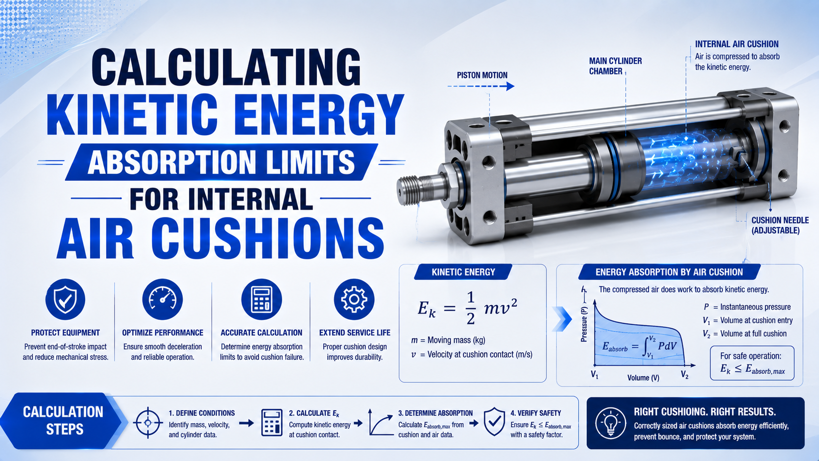
An internal air cushion can stop a moving cylinder load only inside the selected model’s published mass, speed, pressure, and adjustment envelope. Start with the moving assembly’s kinetic energy at cushion entry, then follow that manufacturer’s comparison method. Some catalogs specify allowable kinetic energy; others use load-speed graphs or rating numbers that already account for product geometry. This distinction matters because a correct calculation can still be compared with the wrong limit. The basic moving-load kinetic energy calculation is only the first step. Chamber volume, bore size, or a guessed peak pressure cannot replace the exact cylinder catalog.
Key Takeaways
- SMC CA2 air-cushion ratings span 2.8 to 29 J across five bore sizes.
- Use measured cushion-entry speed, not automatically average stroke speed.
- Follow the selected model’s definition of kinetic, collision, or absorbed energy.
- Choose external deceleration when any published limit is exceeded.
What Does a Published Internal Air Cushion Limit Mean?
SMC lists 2.8, 4.6, 7.8, 16, and 29 J as allowable kinetic energy when the air cushion is activated on CA2 cylinders from 40 to 100 mm bore (SMC CA2 catalog, retrieved 2026-07-23). Those values belong to that series and its stated operating conditions.
An internal air cushion energy limit is a product-specific acceptance boundary for the energy, mass-speed combination, or rating defined by the manufacturer. It is not the amount of thermodynamic energy that an imaginary sealed air volume could store before reaching an assumed pressure.
In particular, catalog terminology requires attention. Three labels that sound similar can describe different checks:
| Catalog term | What it may represent | Correct comparison |
|---|---|---|
| Allowable kinetic energy | Moving energy permitted at cushion entry under stated conditions | Compare with unless the catalog instructs otherwise |
| Allowable collision energy | Residual energy permitted when the piston reaches the mechanical end | Do not treat it as total cushion absorption capacity |
| Absorbed energy | Kinetic energy plus defined propelling or gravity work | Use the manufacturer’s complete absorbed-energy equation |
| Load-speed cushion graph | Approved combinations of moving mass and entry speed | Plot both inputs on the graph; do not convert the curve into a generic joule limit |
| Cushion rating number | A catalog-specific index linked to another table | Compare rating numbers only within that catalog method |
For example, the distinction is visible inside one product family. SMC’s C55 auto-air-cushion data separates allowable energy at cushion entry from allowable collision energy at the end position. For a 100 mm bore, the two published values are 13.2 J and 4.54 J respectively (SMC C55 catalog, retrieved 2026-07-23).
Accordingly, treat each label as a defined test boundary. If a catalog gives both entry and collision limits, passing one does not prove compliance with the other. If it gives only a load-speed curve, the curve is the limit.
For the operating sequence behind the rating, see the high-speed cylinder air-cushion guide. This article stays with the calculation and acceptance boundary.
Which Energy Terms Belong in the Calculation?
SMC’s MY2 selection method divides absorbed energy into kinetic energy and thrust energy, then changes the thrust term for horizontal, vertically downward, and vertically upward motion (SMC MY2 catalog, retrieved 2026-07-23). That is one defined method, not a universal instruction for every cylinder.
Specifically, begin by identifying what the selected catalog asks you to calculate:
- Kinetic-energy method: calculate moving energy at cushion entry and compare it with an allowable kinetic-energy table.
- Load-speed method: compare measured mass and entry speed directly with a cushion chart.
- Absorbed-energy method: add the energy terms named by the supplier, such as continuing thrust or gravity work through the stopping stroke.
- Rating-index method: convert mass and speed to a catalog rating, then compare that rating with the selected bore, rod, and circuit configuration.
However, do not add terms merely because they are physically present. A manufacturer’s allowable kinetic-energy table may already be based on a specified pressure, cushion design, and test method. Adding a separate pressure-volume estimate to that limit can double-count effects or create a number the catalog never defines. Conversely, do not stop at kinetic energy when a supplier explicitly asks for propelling work. ACE’s external shock-absorber method, for example, uses kinetic energy per cycle, propelling-force energy, total energy per event, and total energy per hour as separate quantities (ACE Controls, retrieved 2026-07-23). That method applies to the absorber selection it documents.
Therefore, a useful worksheet starts with a method field:
| Worksheet field | Evidence to record |
|---|---|
| Cylinder series and complete model | Catalog or configured datasheet |
| Cushion type | Adjustable air, self-adjusting air, elastomer, or other |
| Limit type | Energy table, collision table, load-speed graph, or rating index |
| Reference pressure and circuit | Exact catalog note or graph condition |
| Moving-mass definition | Which cylinder parts, carriage, tooling, and load are included |
| Speed definition | Cushion-entry, impact, maximum, or average speed |
| Additional work terms | Only those required by the selected method |
How Do You Calculate Kinetic Energy at Cushion Entry?
Parker states that piston speed at the start of cushioning is typically about 50% higher than average speed for its P1F-T selection guidance (Parker P1F-T catalog, retrieved 2026-07-23). Use that statement only as Parker guidance when direct entry-speed measurement is unavailable.
For translating motion, kinetic energy at cushion entry is:
is kinetic energy in joules, is total translating mass in kilograms, and is cushion-entry speed in metres per second. Kilograms and metres per second produce joules directly.
Specifically, build the moving mass from the installed assembly:
Include the product, fixture, moving plate, fasteners, rod or carriage, and any coupled mechanism that translates with the axis. Do not add the fixed cylinder body or stationary frame. For linkages and rotary mechanisms, calculate reflected mass or rotational energy instead of forcing every component into a direct linear sum. Importantly, speed deserves the same discipline. Measure it as close as practical to cushion engagement with a position trace, encoder, or two sensors over a known short distance. Average full-stroke velocity can hide acceleration and valve delays. The cushion-capacity load-speed chart guide explains how to plot the measured pair.
Alternatively, if only flow and area are known, the Cylinder Speed Calculator can provide a preliminary estimate. It does not replace a measured entry speed because compressibility, back pressure, valve conductance, and load motion change the actual result.
Consequently, the squared speed term makes errors costly. A 20% speed underestimate produces a kinetic-energy result only 69.4% of the correct value:
In contrast, actual speed at produces ${1.2}^2 = 1.44$ times the expected energy. That is why an average-speed estimate should be replaced with a measured cushion-entry value before final acceptance.
Mass errors scale linearly; speed errors scale quadratically. Improving the speed measurement often changes the selection more than refining a small bracket-mass estimate.
Drive Force and Gravity During Cushioning
SMC’s MY2 method uses $F s$ for horizontal thrust work, $(F + mg)s$ for vertically downward motion, and $(F - mg)s$ for vertically upward motion (SMC MY2 catalog, retrieved 2026-07-23). The catalog therefore defines three directional cases. Apply these terms only when the chosen product method requires them.
For example, for a horizontal move with continuing net propelling force:
is drive work in joules, is the net force that continues pushing toward the stop in newtons, and is the defined cushion or absorber stroke in metres.
For gravity acting through the same stopping distance:
is positive when gravity drives the mass farther into the stop and negative when gravity opposes that motion. Use . The distance is the relevant cushion or absorber stroke, not automatically the cylinder’s full travel.
When the selected method requires all three terms, write:
Notably, the sign and force definition must match the manufacturer’s diagram. Theoretical cylinder force from bore area and supply pressure can overstate or understate the force present during deceleration. Active-chamber pressure may fall, exhaust back pressure may rise, and machine friction may oppose motion. Use measured or defensible worst-case force when the catalog does not prescribe another value. Therefore, avoid mixing methods. If a cylinder catalog says to compare load and speed with a curve drawn at 6 bar, adding a separate term and then comparing the sum with that curve has no defined meaning. Stay inside one manufacturer’s selection path from input to acceptance.
Why Can’t Bore Size or Chamber Volume Set the Limit?
Festo specifies 2.5 J of impact energy in the end positions and a 31 mm cushioning length for one 100 mm DSBC configuration (Festo DSBC-100 technical data, retrieved 2026-07-23). SMC’s 100 mm CA2 instead lists 29 J of allowable kinetic energy with its air cushion activated.
However, those numbers should not be compared as if they were the same metric. They have different labels, product constructions, conditions, and acceptance meanings. Their disagreement is useful because it proves that bore size alone cannot determine a transferable energy limit.
In fact, the thermodynamic relationship
describes boundary work for a pressure-volume process. It does not reveal the actual needle-flow history, heat transfer, cushion engagement geometry, seal leakage, opposite-chamber drive, end-cap stress, or the manufacturer’s permissible residual collision. A theoretical calculation can support a simulation, but it cannot create a catalog rating for an unknown cylinder.
Additionally, chamber volume changes dynamically. Once the cushion spear closes the main exhaust path, the piston shrinks the trapped volume while air leaves through an adjustable restriction. Pressure depends on both processes. The adjustable cushion needle flow analysis covers that compressible-flow problem.
Specifically, several product details can change capacity without changing nominal bore:
- cushion spear diameter and engagement length;
- adjustable or fixed restriction geometry;
- cushion seal leakage and check-valve design;
- piston, carriage, and rod moving mass;
- allowable pressure and structural stress;
- operating direction and effective piston area;
- exhaust back pressure and meter-out circuit;
- allowable residual impact at the mechanical end.
Bore is a search key for the correct data table, not the capacity equation. Chamber volume is a model input only when the supplier provides the rest of the transient model and a validated acceptance limit.
How Do You Read Manufacturer Cushion Charts?
Parker’s 4MA method first converts total moving weight and maximum speed into a required cushion rating, then compares that number with separate table values for circuits with and without back pressure (Parker engineering data, retrieved 2026-07-23). This is a two-stage catalog check.
Accordingly, use the format supplied with the selected series:
- Confirm the graph’s pressure, direction, mounting, rod, cushion, and circuit assumptions.
- Calculate or measure the exact inputs named on the axes.
- Include the moving piston, rod, or carriage mass when required.
- Plot the operating point or calculate the catalog rating.
- Select the matching bore, rod diameter, and direction table.
- Repeat for both extension and retraction if both ends use cushioning.
- Reject the point if it falls outside any speed, pressure, mass, energy, or adjustment limit.
Importantly, back pressure can change the result. Parker’s 4MA table gives different cushion ratings for “No Back Pressure” and “With Back Pressure,” and instructs users to consult the factory where exhaust-line back pressure can exceed the stated conditions. A silencer, long tube, valve, or meter-out restriction can therefore invalidate a table selection even when the energy arithmetic is correct. Similarly, the chart may encode nonlinear geometry. Parker’s rodless-cylinder guidance says reducing cushioning distance by 50% can reduce cushion effectiveness by 60% to 70% (Parker rodless-cylinder catalog, retrieved 2026-07-23). Do not scale capacity directly with shortened stroke.
Worked Example: Checking a 63 mm SMC CA2
For a 63 mm CA2, SMC publishes 7.8 J allowable kinetic energy with the air cushion activated and a piston-speed range of 50 to 500 mm/s (SMC CA2 catalog, retrieved 2026-07-23). Both limits belong in this screening example.
For example, assume the verified total moving mass is 30 kg and measured cushion-entry speed is 0.50 m/s. The calculation is:
The energy-use ratio against the published 7.8 J value is:
The application uses 48.1% of the listed allowable kinetic energy, and 0.50 m/s equals the top of the published piston-speed range. It passes these two screening checks. That statement does not certify mounting, side load, cushion adjustment, valve circuit, pressure, temperature, or repeated-cycle behavior.
In contrast, change only the measured entry speed to 0.75 m/s:
As a result, this point fails twice. The calculated energy exceeds 7.8 J, and 0.75 m/s exceeds the catalog’s 0.50 m/s piston-speed maximum. Selecting on energy alone would miss the independent speed violation.
Importantly, do not apply this 7.8 J value to another 63 mm cylinder. SMC’s C55 auto-cushion data lists 5.3 J allowable energy at cushion entry for its 63 mm model, demonstrating that identical nominal bore does not create identical capacity.
When Is an External Shock Absorber Necessary?
Parker instructs users to choose another or external deceleration method when the required kinetic-energy rating exceeds the selected 4MA cushion rating after its two-stage graph-and-table comparison (Parker engineering data, retrieved 2026-07-23). A tighter needle cannot expand the published operating envelope.
Therefore, change the stopping strategy when any of these conditions applies:
- required energy, mass, or cushion-entry speed exceeds the exact catalog limit;
- the operating point changes enough that one needle setting cannot avoid both impact and rebound;
- exhaust back pressure or circuit conditions fall outside the published chart;
- peak pressure, end-cap load, or residual impact remains unacceptable during commissioning;
- production speed cannot be reduced enough to regain margin;
- the cylinder lacks enough cushion length for the required deceleration profile.
For instance, the first corrective action is often lower cushion-entry speed because kinetic energy changes with speed squared. A valve adjustment that reduces only central stroke speed is not enough unless the entry speed also falls. The deceleration-profile guide explains how to separate useful travel from the stopping zone. Alternatively, if throughput or load prevents a speed reduction, use a larger or differently cushioned cylinder, servo-pneumatic control, or a properly selected external absorber. The external shock absorber sizing guide adds per-event energy, continuing drive work, hourly energy, effective mass, impact velocity, return time, temperature, and mounting checks.
In addition, commissioning remains necessary after a catalog pass. Record cushion-entry position and speed, both chamber pressures where practical, needle reference, rebound, final impact, and cycle-to-cycle variation. If an initially acceptable stop becomes harsh, use the cylinder cushion failure diagnostic sequence before turning the needle farther closed.
Internal Air Cushion Energy FAQs
SMC’s CA2 catalog pairs five air-cushion energy values with a 50 to 500 mm/s piston-speed range, while Parker’s 4MA method separates ratings with and without back pressure (SMC; Parker, retrieved 2026-07-23). These FAQs keep each limit tied to its source.
Can chamber volume determine maximum internal cushion energy?
No. Chamber volume is one physical input, but it does not define the needle-flow history, heat transfer, cushion geometry, seal leakage, structural limit, or allowable residual impact. Use volume only inside a validated model. For selection, compare the application with the exact manufacturer’s energy table, rating method, or load-speed graph.
Which velocity belongs in the kinetic-energy equation?
Use piston velocity at cushion engagement or the impact point specified by the manufacturer. Do not automatically use full-stroke average speed. Parker notes that cushion-entry speed can be about 50% above average in its P1F-T guidance, while direct position or sensor measurement provides better application-specific evidence.
Must cylinder thrust always be added to kinetic energy?
No. Add continuing thrust only when the selected manufacturer’s method requires an absorbed-energy calculation that includes it. SMC’s MY2 method does; SMC’s CA2 table is labeled allowable kinetic energy. Mixing a thrust-energy formula with a table that uses another definition can double-count effects and invalidate the comparison.
Does operating below the listed energy guarantee a safe stop?
No. Energy is only one limit. The application must also satisfy piston speed, pressure, load, mounting, side-load, circuit, direction, temperature, and adjustment requirements. In the 63 mm CA2 example, 8.44 J fails the 7.8 J energy value and its 0.75 m/s speed also exceeds the 0.50 m/s catalog maximum.
When should an external shock absorber replace internal cushioning?
Use external deceleration when the operating point exceeds any internal-cushion limit, load or speed varies beyond one stable setting, or commissioning cannot eliminate impact without rebound or slow final travel. Select the absorber separately for energy per event, continuing drive work, energy per hour, effective mass, velocity, stroke, temperature, and mounting.
Sources and technical references
- SMC CA2 Series Air Cylinder Catalog. Retrieved 2026-07-23.
- SMC C55 Series Auto Air Cushion Catalog. Retrieved 2026-07-23.
- SMC MY2 Series Mechanically Jointed Rodless Cylinder Catalog. Retrieved 2026-07-23.
- Parker 4MA Application Engineering Data. Retrieved 2026-07-23.
- Parker P1F-T ISO Cylinder Catalog. Retrieved 2026-07-23.
- Parker Rodless Pneumatic Cylinder Catalog. Retrieved 2026-07-23.
- Festo DSBC-100-25-PPVA-N3 Technical Data. Retrieved 2026-07-23.
- Festo, Cylinder Cushioning: The Three Most Common Methods. Published 2022-07-07; retrieved 2026-07-23.
- ACE Controls, Calculation Bases for Industrial Shock Absorbers. Retrieved 2026-07-23.