

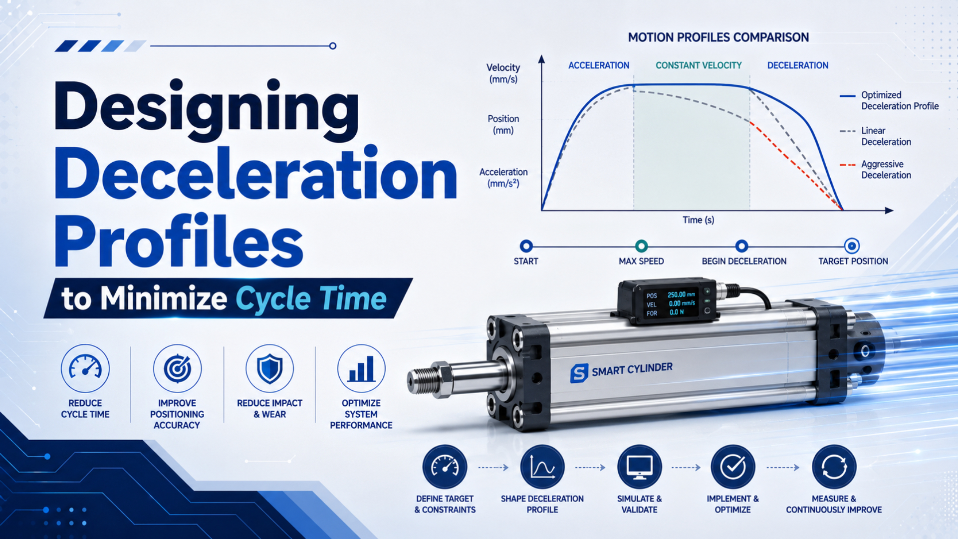
A pneumatic cylinder deceleration profile is the measured or commanded change in velocity as a moving load approaches its target. The fastest usable profile is not the one with the highest cruise speed or the shortest theoretical ramp. It is the profile that reaches the position window quickly, stays there, and keeps the cylinder, guide, tooling, cushion, and stop within their specified limits.
That definition separates two systems that are often confused. A cylinder driven by an on/off valve and adjustable air cushion develops a passive end-of-stroke response from trapped air and exhaust restriction. A servo-pneumatic axis can command a velocity ramp before the cushion zone. Both decelerate the load, but only the second system generates a programmable motion profile.
Key Takeaways
- Parker warns that cushion-entry speed is typically about 50% above average stroke speed.
- Optimize deceleration time and settling time together.
- Calculate kinetic energy, continuing drive work, and duty-cycle heat before approving a stop.
- Use model-specific cushion limits rather than a generic percentage of cylinder force.
What Is a Deceleration Profile in a Pneumatic System?
Festo groups pneumatic-cylinder end cushioning into 3 broad methods: elastic, pneumatic or servo-pneumatic, and hydraulic damping (Festo, 2022). A deceleration profile therefore describes how velocity falls, while the hardware and control architecture determine whether that shape is commanded, passively produced, or both.
In a basic on/off circuit, the cylinder accelerates and travels according to pressure, flow, load, friction, and changing chamber volume. Near the end cap, a cushion seal traps exhaust air. The cushion needle meters that air out, chamber pressure rises, and the resulting backpressure slows the piston. The controller may command only “extend” or “retract.” The velocity curve is a measured response, not an independently programmed trajectory.
A proportional or servo-pneumatic axis adds continuous control authority. The controller can reduce its velocity command before the physical cushion zone, shape acceleration and jerk, then use the internal cushion or an external stop as the final energy-management layer. The proportional-valve position-control guide explains the feedback, valve, sensor, and controller boundary required for that type of axis.
The same language should not be used for both systems without qualification:
| System | What creates deceleration? | What can be tuned? | What must be measured? |
|---|---|---|---|
| On/off valve plus elastic bumper | Material deformation and impact | Travel speed and hardware selection | Entry speed, impact, rebound, settling |
| On/off valve plus air cushion | Trapped-air backpressure and exhaust restriction | Speed control and cushion needle | Entry speed, cushion pressure, impact, settling |
| Proportional or servo-pneumatic axis | Commanded motion plus pneumatic and mechanical damping | Speed, deceleration, jerk, limits, cushion | Command, position, velocity, pressure, output, settling |
| External hydraulic shock absorber | Viscous energy absorption over rated stroke | Model, stroke, placement, adjustment where provided | Impact speed, energy per cycle, energy per hour |
Cycle Time Includes Deceleration and Settling
Rockwell documents 2 principal commanded velocity profiles, trapezoidal motion for linear acceleration and deceleration, and S-curve motion for controlled jerk (Rockwell Automation, 2025). Whichever profile is used, machine cycle time ends only after the axis enters and remains inside its production-ready position and stability limits.
Break the motion into a measurable budget:
Here, covers command-to-motion delay, acceleration, travel at the main speed, intentional slowing, the time until the acceptance window remains satisfied, and the machine operation performed after arrival. All terms use seconds.
Reducing does not help if impact and rebound add more . Excessive cushioning causes the opposite failure: the piston creeps through a long final approach even though it does not rebound. The useful optimization target is:
Measure from a frozen event definition. For example, start when the axis crosses the declared deceleration position and finish only when position, velocity, and any required vibration or pressure signal remain inside their limits for the stated dwell. A reed-switch transition alone cannot show rebound between scans.
Command-to-first-motion delay belongs to a different part of the budget. The cylinder response-time and dead-volume guide covers that starting event; this article concentrates on the final approach and stable completion.
The highest cruise speed can produce a slower machine. If extra kinetic energy forces an earlier deceleration point, causes valve saturation, or lengthens settling, the total move may take longer. Optimize the complete recorded trace, not the largest velocity number on a controller screen.
How Do You Calculate Stopping Distance and Time?
Parker states that piston speed at the start of cushioning is typically about 50% higher than average stroke speed and says this higher value governs cushion selection (Parker P1F catalogue, accessed 2026). Use measured cushion-entry velocity, not stroke length divided by total travel time, as the stopping calculation input.
For an ideal monotonic stop from entry velocity to final velocity over distance , the magnitude of constant average deceleration is:
The velocities use metres per second, uses metres, and is in metres per second squared. This kinematic result assumes one constant deceleration and does not predict the peak force or pressure of a pneumatic cushion.
If velocity falls linearly, the ideal deceleration time is:
This relationship is useful for a first trajectory check. A real air cushion rarely produces a linear velocity ramp because chamber pressure, exhaust mass flow, friction, drive pressure, and effective volume all change during the stop.
Corrected worked example
Consider an externally guided 25 kg moving mass entering a planned 80 mm deceleration zone at 1.2 m/s and ending near zero velocity. The ideal constant-deceleration screen gives:
The corresponding average inertial force magnitude is:
The ideal linear-ramp stopping time is:
These three values describe ideal motion only. They do not prove that a cylinder end cap, cushion seal, guide, or stop can withstand the event. They also exclude continuing pneumatic drive force, gravity, rotational inertia, pressure transients, peak deceleration, and rebound. The next check must use the exact cylinder or shock-absorber rating.
Cushion Energy Is More Than Kinetic Energy
ACE identifies 5 basic shock-absorber sizing inputs: mass, impact velocity, propelling force, cycles per hour, and the number of absorbers working in parallel (ACE Controls, 2017). This boundary prevents a common error, sizing the stop from moving-mass kinetic energy while ignoring the actuator force that continues doing work during deceleration.
The translational kinetic energy at cushion entry is:
Here, is the effective translational mass in kilograms and is entry velocity in metres per second. The result is joules. Convert rotating tooling or coupled mechanisms to an equivalent mass only with a documented mechanical model.
If a net propelling force continues in the direction of motion through stopping distance , its approximate work is:
The first energy screen then becomes:
The sign and magnitude of depend on cylinder pressure, opposing chamber pressure, gravity, friction, orientation, and external process forces. For a vertical axis, potential-energy change must be included with the correct sign. For an external shock absorber, also check the manufacturer’s permitted energy per cycle, energy per hour, effective mass range, impact speed, stroke, side-load angle, temperature correction, and mounting alignment.
In the 25 kg example, kinetic energy is . That is not yet the required cushion rating. If pneumatic force continues to push the load through the 80 mm zone, its work must be added before comparing the result with a model-specific chart or data sheet.
Do not compare average inertial force with theoretical cylinder thrust and call the difference a structural safety margin. Cylinder thrust describes pneumatic output under stated pressure. End-cap capacity, carriage moments, cushion energy, and shock-absorber ratings are different limits.
Which Profile Should You Use: Trapezoidal, S-Curve, or Passive Cushioning?
Rockwell describes 2 programmable choices: a trapezoidal profile for the fastest linear acceleration and deceleration, and an S-curve profile that controls jerk but can increase ramp time (Rockwell Automation, 2025). A passive air cushion is neither profile; its velocity shape emerges from pneumatic conditions near the end cap.
Trapezoidal command
Choose a trapezoidal velocity profile when the controlled axis can tolerate the abrupt change in acceleration and the priority is minimum commanded ramp time. Verify that valve flow, pressure, feedback, mechanics, and the remaining cushion can follow the command without saturation or overshoot. A perfect command shape does not guarantee matching cylinder motion.
S-curve command
Choose an S-curve when jerk excites vibration, product motion, frame deflection, or sensor instability. Rockwell defines jerk as the rate of change of acceleration or deceleration. Adding jerk limitation smooths acceleration transitions, but the added ramp time and stopping distance must be included in the cycle budget.
Passive air cushioning
Use model-specific pneumatic cushioning when the mass and entry speed stay inside the selected cylinder’s published cushion envelope. Festo explains that adjustable cushioning meters trapped air and that its setting depends on mass, speed, working pressure, and resistance. For the sizing foundation, use the high-speed air-cushion guide.
The architectures can work together. A servo-pneumatic axis can command most of the deceleration before entering a physical cushion zone. The cushion then manages residual energy and abnormal approach conditions within its rating. It should not be treated as a substitute for the machine’s risk-assessed stop function.
How Should You Set the Deceleration Start Point?
Parker’s cushion-sizing guidance uses mass and maximum permissible speed at cushion entry and warns that entry speed is typically 50% above average speed (Parker P1F catalogue, accessed 2026). Set the active deceleration point from measured velocity, available distance, hardware limits, controller delay, and the required final position window.
For a commanded constant-deceleration screen, calculate the minimum ideal distance:
Here, is the maximum permitted deceleration magnitude from the load, guide, product, controller, and actuator limits. Add distance for valve and controller delay, jerk-limited ramps, uncertainty, and residual cushioning. Do not place the command transition exactly at the theoretical minimum.
A practical starting process is:
- Record the present position and velocity trace with the production load.
- Identify physical cushion entry from the velocity or pressure change, not only from a drawing.
- Define the maximum entry velocity allowed by the exact cylinder cushion chart.
- Calculate an initial active deceleration position with margin for timing and load variation.
- Run at reduced speed and verify direction, feedback, limits, and the full-stop state.
- Increase speed or move the deceleration point later in small controlled steps while logging the same signals.
What should move first, the speed or the deceleration point? Change one variable at a time. If both change together, a shorter cycle does not reveal whether the improvement came from higher cruise velocity, later braking, a different cushion response, or a longer hidden settling event.
For on/off circuits, the physical cushion length is model-specific and usually not adjustable. The needle changes exhaust restriction, not the geometric start position. An upstream flow control changes travel speed but does not create position-based braking. The air-compressibility guide explains why trapped volume and pressure make the final response nonlinear.
A Trace-Based Commissioning Procedure
SMC’s CK1 manual limits its specific cushion-valve adjustment to 2.0 turns and warns that a fully closed valve can cause rebound, incomplete travel, or cushion-seal damage (SMC, accessed 2026). That model-specific warning illustrates the correct method: follow the selected manufacturer’s adjustment range and judge the result from recorded motion.
1. Freeze the acceptance boundary
Define maximum entry speed, maximum dynamic and final position error, permitted rebound, settling window, impact or vibration limit, pressure range, payload range, orientation, and cycle rate. If noise is an acceptance metric, state the instrument, distance, weighting, and time response rather than citing an unrelated occupational exposure number.
2. Instrument the final approach
Record command, measured position, calculated or measured velocity, valve output, inlet pressure near the valve, both chamber pressures when available, end sensor, and the machine-ready signal on one clock. Use enough sampling resolution to see the cushion event and rebound.
3. Establish a low-energy baseline
Start with the actual load and conservative speed. Confirm alignment, guide freedom, sensor scaling, cushion-valve position, speed-control direction, and end-stop contact. Check both stroke directions separately because rod-side area, gravity, tube routing, and exhaust paths can differ.
4. Adjust one end at a time
For an adjustable air cushion, follow the exact product manual. Seek a controlled arrival without hard impact, rebound, or a long final crawl. Do not copy a turn count from another bore, series, load, or speed. Record the final setting in a reproducible form.
5. Optimize the complete end event
Compare , , peak pressure, entry velocity, final error, and repeatability after each change. A later braking point is useful only if the energy rating and stable-arrival limits still pass.
In our experience, a position trace without valve command and pressure usually leaves the most important question unanswered. In reviews where our team analyzed synchronized signals, we found a useful diagnostic split. Saturated output points toward missing control authority. A pressure spike with rebound points toward the stop event. A slow approach with unsaturated output points back to the profile, friction, or controller settings.
6. Validate the operating envelope
Repeat at minimum and maximum specified supply pressure, light and heavy payload, both directions, cold and warm conditions where relevant, and the maximum planned cycle rate. A setting that passes one nominal cycle is not a production qualification.
When Is an External Shock Absorber Required?
Parker directs users to add external shock absorbers when moving mass and cushion-entry speed exceed the selected cylinder’s published cushioning limits (Parker OSP-P catalogue, accessed 2026). The decision must also consider drive energy, repeated-cycle heat, stop placement, guide moments, orientation, and abnormal-stop requirements.
Use an external shock absorber or another engineered stop when one or more conditions apply:
- the operating point is outside the cylinder’s mass-versus-entry-speed cushion chart;
- required energy per cycle or per hour exceeds the internal or external device rating;
- the built-in cushion cannot meet the stable-arrival time without hard impact or long creep;
- the load or guide requires the stopping force near its centre of gravity;
- the axis must manage energy after loss of normal control;
- production variability exceeds the adjustable cushion’s validated range.
Placement matters. A shock absorber offset from the load centre can introduce yaw, bearing load, or carriage moment even when its energy rating is adequate. Parker’s rodless-cylinder guidance recommends fitting additional shock absorbers near the centre of gravity when cushion limits are exceeded. The external shock-absorber sizing guide covers effective mass, side load, mounting, and capacity checks.
Do not use a shock absorber as the machine’s only positive end stop unless its documentation explicitly permits that role. Some installations require a separate mechanical stop to define position while the absorber dissipates energy. Guard the moving load and control stored pneumatic and gravitational energy according to the machine risk assessment.
What Must the Acceptance Test Record?
ISO 4414:2010 is a 38-page, third-edition standard covering pneumatic-system design, installation, adjustment, operation, and maintenance, and ISO confirmed it current in 2021 (ISO). A defensible deceleration profile therefore needs recorded operating conditions and fault behaviour, not one unloaded cycle or an unqualified “smooth stop” observation.
Record these inputs and results:
| Record | Required detail | Why it matters |
|---|---|---|
| Motion command | Profile type, speed, deceleration, jerk, start position | Reproduces the requested motion |
| Cylinder and guide | Model, bore, stroke, cushion type, orientation, load centre | Defines mechanical and cushion limits |
| Valve and air path | Valve model, flow rating, tube ID and length, exhaust devices | Exposes flow and delay restrictions |
| Payload | Total moving mass, rotating inertia, process force, direction | Sets kinetic and drive energy |
| Air conditions | Dynamic inlet and chamber pressures, temperature where relevant | Shows available force and cushion behaviour |
| Timing | Delay, acceleration, cruise, deceleration, settling, complete move | Prevents hidden time from being ignored |
| Stop quality | Entry velocity, peak pressure, rebound, final error, vibration or noise method | Verifies the final approach |
| Duty | Cycles per hour, consecutive cycles, warm-up state | Checks heat and repeatability |
| Fault response | Sensor loss, valve fault, low pressure, power loss, emergency stop | Confirms the specified machine state |
Approve the profile only after every required load and pressure condition remains inside its limits. Preserve raw traces, software revision, controller task period, filter settings, cushion setting, and instrument information. A maintenance technician should be able to reproduce the test after replacing a valve, cylinder, seal, tube, or shock absorber.
For a quick travel-time screen, the Stroke Time Calculator can compare stroke and average speed. It cannot calculate nonlinear cushioning, rebound, jerk-limited motion, or settling. Use it for the cruise budget, then verify the complete end event from measured traces.
For site ownership, author context, or technical corrections, see About Bepto and Contact. A project review should include the cylinder and valve models, moving mass, entry velocity, pressure traces, deceleration distance, cycle rate, and acceptance limits.
Deceleration Profile FAQs: What Should Engineers Check?
ACE requires 5 primary inputs before selecting an industrial shock absorber, while Parker warns that cushion-entry speed can be about 50% above average stroke speed (ACE, 2017; Parker, accessed 2026). These 5 answers keep profile choice, energy, adjustment, and acceptance tied to the installed machine.
Does an adjustable air cushion create an S-curve profile?
No. An adjustable cushion meters trapped exhaust air and produces a load-dependent pneumatic response near the end cap. A programmed S-curve requires continuous motion control with a position reference and jerk setting. The two can work together, with active control performing the planned slowdown and the physical cushion managing rated residual energy.
Which velocity should be used for cushion selection?
Use measured or conservatively estimated velocity at cushion entry. Do not rely only on average stroke speed. Parker says cushion-entry speed is typically about 50% higher than average speed, but that is a selection warning rather than a universal conversion. Verify the actual profile against the exact cylinder’s mass-speed cushion chart.
Should the cushion valve be closed fully for maximum braking?
Not unless the exact product instructions explicitly require that condition. SMC warns for its CK1 series that a fully closed cushion valve can cause rebound, incomplete travel, or seal damage. Follow the model-specific adjustment direction and range, then confirm arrival from position, pressure, impact, and settling measurements under the real load.
How can you tell whether a cylinder is over-cushioned?
An over-restricted cushion often shows an early velocity drop followed by a slow final approach, delayed end-sensor transition, or failure to complete the stroke. Confirm it from synchronized position, velocity, pressure, and ready-signal traces. Similar symptoms can also come from insufficient pressure, restricted exhaust, misalignment, contamination, or load change.
When should an external shock absorber replace the built-in cushion?
Use an external device when the cylinder’s mass-speed cushion limit is exceeded, the required energy per cycle or hour is too high, or the internal cushion cannot meet impact and settling limits together. Check effective mass, drive force, stroke, side load, temperature, placement, duty cycle, and the need for a separate mechanical stop.
Sources and technical references
- Parker P1F pneumatic-cylinder catalogue, cushion-entry speed and mass-speed selection guidance.
- Festo cylinder cushioning methods, 2022.
- ACE industrial shock-absorber calculation catalogue, 2017.
- Rockwell Automation Integrated Motion manual, 2025.
- SMC CK1 operating manual, cushion and speed-controller adjustment guidance.
- ISO 4414:2010, pneumatic fluid power safety requirements.