

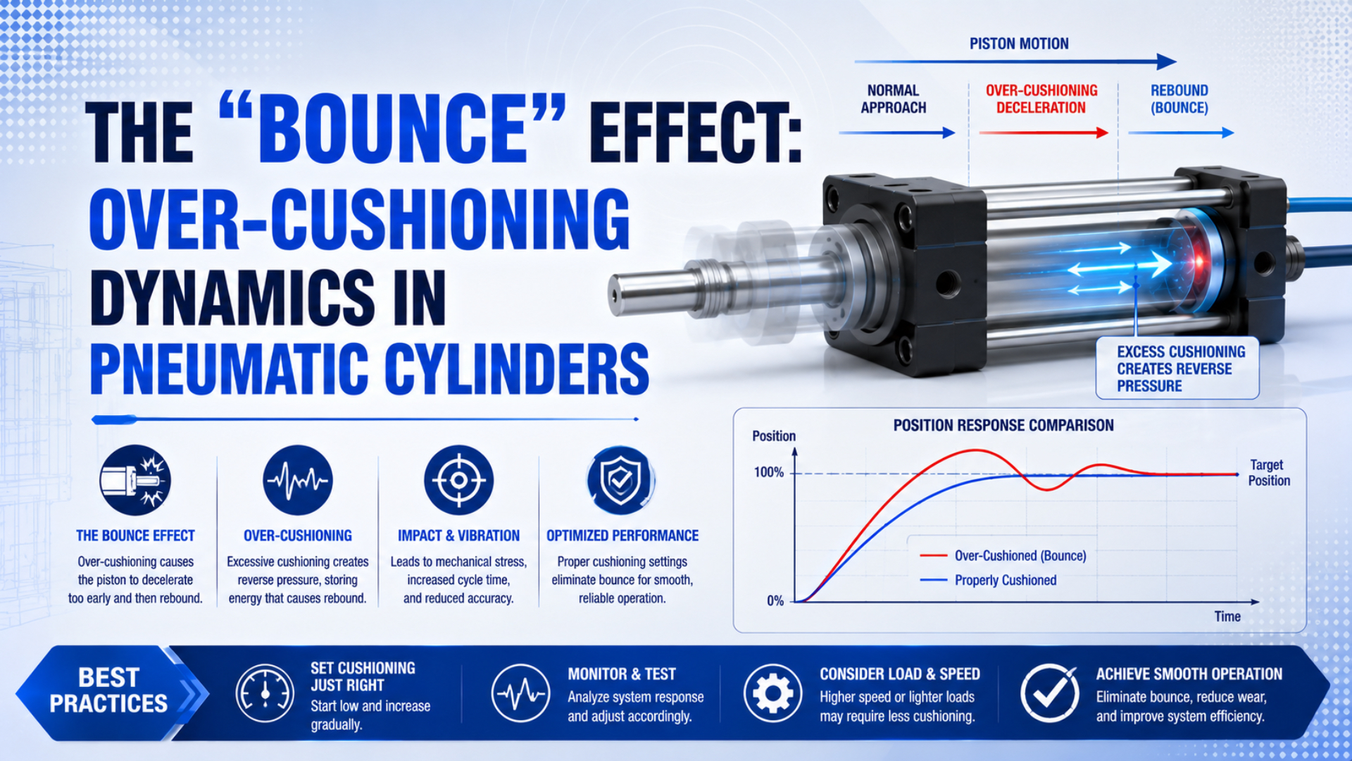
Over-cushioning is excessive exhaust restriction inside an adjustable cylinder end cushion. Trapped pressure may delay final travel. It can stop the piston before the end cap or push it back before pressure decays. The cure is not a universal number of needle turns. It is a controlled adjustment based on synchronized position, pressure, load, speed, and the exact cylinder manual. This guide addresses that narrow fault. Read the physics of pneumatic cylinder bounce for the wider air-spring mechanism and other causes of rebound.
Key Takeaways
Reliable cushion tuning rests on evidence from the exact machine, not on a generic turn count. First prove where the abnormal motion begins. Then change one setting safely, compare synchronized signals, and confirm that the final result still works throughout the specified load, pressure, speed, and temperature envelope.
- Over-cushioning means excessive cushion-phase exhaust restriction.
- A pressure rise alone proves nothing. Relate it to piston position, valve command, direction of motion, and the instant the cushion mechanism engages.
- Follow the installed cylinder’s adjustment procedure.
- When acceptable motion requires a nearly open needle, stop tuning around the symptom. Verify entry speed, moving mass, continued drive work, cushion capacity, exhaust hardware, and mounting stiffness before production resumes.
- Record the final setting with the complete operating envelope so another technician can reproduce it after maintenance.
What Does Over-Cushioning Actually Mean?
Near stroke end a cushion spear or sleeve closes the normal exhaust path. Remaining air then passes through a needle-controlled restriction. Festo describes the trapped air as a pressure force opposing piston motion and identifies mass, speed, working pressure, plus cylinder resistance as adjustment factors (Festo, 2021).
Proper restriction has a narrow job: decelerate the assembly and complete the stroke without hard impact. A needle set too far open leaves excess piston speed; a nearly closed path can instead arrest the piston early or push it briefly backward.
Similar visible motion can come from elsewhere. Flexible stops, loose mounting, valve switching, low breakaway margin, contaminated seals, and control-loop hunting may also create a second movement. Mislabeling those faults sends the technician to the wrong adjuster.
Why Can a Nearly Closed Cushion Needle Cause Rebound?
Parker states that a deeper cushion needle reduces exhaust flow, allowing back pressure to slow the piston (P1F-T catalogue). Excessive restriction can let pressure in the shrinking cushion volume overcome the remaining drive and load forces.
Real cushion motion is nonlinear. While the available volume shrinks rapidly, gas temperature changes and seal friction varies with velocity. Supply pressure also moves, and the valve, fittings, tubing, silencers, plus cushion passage impose separate flow limits. None of those effects stays constant through the event. A single fixed damping ratio therefore cannot describe every cylinder or operating point. Experimental researchers instead recorded displacement, cushion pressure, inlet and outlet line pressures, and impact acceleration while comparing deficient, optimum, and excessive cushioning (Beijing Institute of Technology, 2002). That multi-signal approach is more useful than assigning one universal rebound threshold.
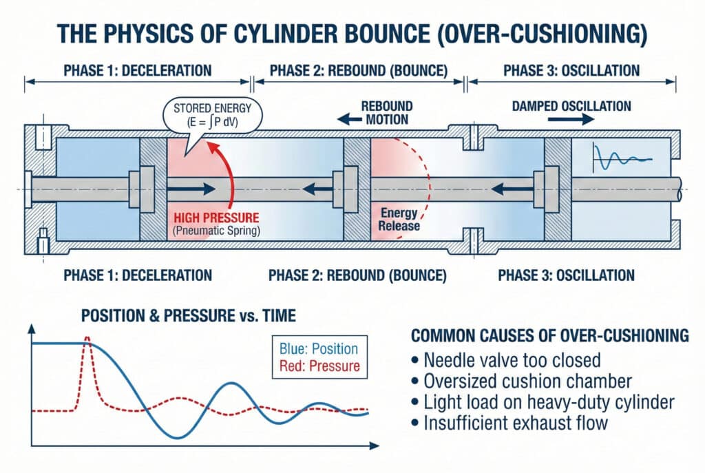
This is a conceptual sequence, not a universal measured trace. Actual pressure, displacement, and settling time depend on the cylinder, circuit, load, speed, and adjustment.
Rather than asking for a universal damping ratio, identify the force balance and flow restriction at the instant motion slowed, stopped, or reversed.
Which Signals Distinguish Over-Cushioning From Other Faults?
Strong diagnosis combines repeatable motion with dynamic pressure evidence. A 2002 pneumatic-cushion study varied load mass and supply pressure. In that test arrangement, cushion pressure depended mainly on external load, showing why an unloaded bench cycle cannot validate the loaded machine (Kagawa, Kim, Luo, and Xuan, 2002).
| Observed signature | Evidence that supports over-cushioning | Important competing cause |
|---|---|---|
| Piston slows excessively only after entering the cushion zone | Exhaust-side pressure rises as position approaches the end | Undersized exhaust path, clogged silencer, or restricted valve port |
| Piston stops short and then creeps to the end | Cushion pressure decays while drive pressure remains available | Low supply pressure, side load, seal friction, or insufficient force margin |
| Piston reverses briefly near the end | Reversal follows a cushion pressure peak and changes when the cushion restriction changes | Elastic machine stop, structural deflection, or valve command reversal |
| End impact disappears but cycle time becomes unstable | Final-stroke time changes with load or temperature | Lubrication, seal condition, or upstream pressure variation |
| Symptom appears at both ends | Both needles or shared exhaust components show the same restriction pattern | Common valve, silencer, tubing, or controller fault |
Measure both cylinder-port pressures when the risk and hardware allow it. A regulator gauge several metres upstream cannot reveal the local transient.
Next, synchronize those pressures with position or velocity and the valve command. Without one time base, a pressure peak may look causal even when it follows the stop.
Also inspect the basic mechanics before touching the needles. Confirm that mounts are tight, the guided load moves freely, the rod is not side-loaded, the piston completes its stroke at low speed, and no external stop is flexing. Our cylinder cushion failure guide covers damaged seals and blocked passages. Adjustment cannot repair those hardware faults.
A Safe Over-Cushioning Diagnostic Workflow
Begin with the machine risk assessment. Before testing, review guarding, lockout procedure, and the cylinder manufacturer’s instructions. Cushion changes can alter stopping distance or create a hard impact, so start at the lowest practical energy. Keep personnel outside the hazard zone. Never use a hand as an end stop or motion indicator.
- Record the operating point. Capture cylinder model and bore, stroke, orientation, moving mass, load direction, supply pressure at the valve, commanded cycle rate, and current needle position. Mark the original setting so it can be restored.
- Check mechanics at reduced speed. Verify alignment, free movement, mounting stiffness, sensor security, and full stroke. A mechanical bind should be corrected before cushion tuning.
- Time-align the signals. Record position, cap-end pressure, rod-end pressure, and valve command. Calculate velocity from a sufficiently clean position signal rather than judging it by eye.
- Locate the event. Confirm that the abnormal deceleration or reversal starts after the piston enters the cushion zone. If it begins earlier, investigate the main flow path, load, or guidance first.
- Change one variable. Follow the exact manual and move only the relevant cushion needle by a small, recorded increment. Repeat under the same load and pressure.
- Look for causal movement. A credible diagnosis should show the symptom and pressure-position trace improving consistently as restriction is reduced, without introducing hard end impact.
- Repeat the operating envelope. Check minimum and maximum specified load, speed, supply pressure, temperature, and orientation. One comfortable cycle does not establish a production setting.
In our experience reviewing cylinder applications, peak pressure alone tells surprisingly little.
Overlay the final portion of position with both port pressures and valve state. The combined view reveals whether opposing pressure rises before velocity collapses, whether the command stays unchanged, and whether the piston reaches the mechanical end.
How Should the Cushion Needle Be Adjusted?
Treat the service manual as the authority because needle direction, usable travel, locking method, and starting position vary by series. Never copy another cylinder’s turn count; identify the end being adjusted, make the circuit safe, preserve the original setting, and use increments small enough to reveal a clear trend.
The Series RLQ manual provides a useful example of why model identification matters. For RLQ cylinders with 32 to 63 mm bore, SMC lists a shipment setting of one-quarter to one-half turn open and a maximum adjustment range of 2.5 turns. Its procedure says to close the needle fully and then open it gradually (SMC Series RLQ catalogue). Those values apply to that series, not to pneumatic cylinders in general.
Change the needle only after verifying the manufacturer’s defined direction and limit. Then cycle at reduced energy and inspect the pressure-position trace for hard impact.
A good setting produces smooth final deceleration, complete stroke, and stable settling. Once confirmed, secure the locknut or retaining feature provided by the design.
Meter-out speed control and cushion adjustment act on different portions of the stroke. The main meter-out circuit controls cylinder speed, while the cushion restricts flow only near the end.
Reopening the cushion needle cannot repair an undersized valve, collapsed tube, or clogged silencer elsewhere in the exhaust path.
When Is Needle Adjustment Not Enough?
If the cylinder still hits hard after correct adjustment, compare stopping demand with the exact catalogue limit. Make the same check when an acceptable stop requires an impractically low speed. SMC’s RLQ data, for example, lists allowable kinetic energy from 0.15 J for the 32 mm bore to 0.77 J for the 63 mm bore.
That published range belongs to Series RLQ only.
A first-pass energy balance can be written as:
where:
- is the estimated energy the stopping system must manage per event, in joules.
- is the effective moving mass, in kilograms.
- is piston speed at cushion entry, in metres per second, not average stroke speed.
- is the net driving force acting through the cushion zone, in newtons.
- is effective cushion or stopping travel, in metres.
- accounts for gravity or another external load that adds energy during stopping, in joules. Use a negative sign only when it reliably removes energy.
Use this estimate only for screening. It cannot reproduce the selected cylinder’s pressure-temperature history, geometry, friction, or leakage, so the manufacturer’s capacity method and prescribed safety factors remain controlling.
If demand exceeds the internal cushion’s stated capacity, reduce mass or entry speed, select a cylinder with more suitable cushioning, or add a correctly sized external absorber. See our external shock absorber sizing guide before selecting hardware. Adding mass is not a remedy because kinetic energy rises directly with mass at a given speed.
What Should an Acceptance Test Record?
A tuned cylinder is not accepted merely because one cycle looks quiet. The record should prove complete stroke, controlled deceleration, stable settling, acceptable pressure, and repeatable sensing across the machine’s specified operating range. Store the evidence with the cylinder model and the exact needle position so later maintenance can distinguish drift from an undocumented adjustment.
At minimum, retain:
- exact cylinder part number and cushion type;
- bore, stroke, mounting orientation, rod configuration, attached guides, and any external stop that can store or release elastic energy;
- moving mass plus the magnitude and direction of external force;
- measured speed at cushion entry;
- supply pressure at the valve and dynamic pressure at both cylinder ports, recorded on the same time base as position and command;
- relevant machine and ambient temperature;
- needle position, adjustment direction, lock status, tool used, and identity of the technician who approved the setting;
- final position, settling behavior, sensor switching, end-stop contact, cycle rate, and results at every defined operating extreme.
Set pass limits from machine requirements and component documentation. Never borrow a universal rebound distance or settling time. A transfer mechanism may tolerate residual motion after its sensor changes state. The same movement can ruin a camera image. A guarded press may impose a separate safety-sequence limit. Test the worst credible combination of moving mass, external force, entry speed, pressure, temperature, orientation, and cycle rate under recorded production-like conditions; for each run, document the signals, sampling rate, calculation method, acceptance boundary, repetitions, and person approving the result. That record makes later changes in impact or settling measurable. It also prevents arguments about what once looked acceptable during commissioning.
FAQs About Pneumatic Cylinder Over-Cushioning
The short answers cover common troubleshooting and commissioning decisions. They separate evidence from assumption, keep model-specific values in context, and mark the point where cushion adjustment should stop so investigation can move to the mechanics, main pneumatic circuit, or control system.
Is every end-of-stroke rebound caused by over-cushioning?
No. Elastic stops, loose mounts, structural flex, valve switching, seal friction, low force margin, and controller hunting can produce similar motion; evidence of over-cushioning requires the event to begin in the cushion zone, align with opposing pressure, and change consistently after a model-approved reduction in restriction.
Can I diagnose over-cushioning from the regulator gauge?
Usually not. A remote regulator gauge can miss the rapid local change at either cylinder port, so put position, both port pressures, and valve command on one timeline; their sequence is more diagnostic than one peak value.
How many turns should a pneumatic cushion needle be open?
There is no universal setting. Needle geometry and permissible travel vary by cylinder series. SMC’s one-quarter to one-half turn shipment setting and 2.5-turn limit cited above apply only to Series RLQ bores from 32 to 63 mm. Follow the manual for the installed part number.
Will opening the cushion needle always remove bounce?
No. Opening the needle can reduce opposing pressure when excess restriction is the cause. Too much opening creates hard end impact. When the symptom does not change, restore the baseline before investigating mechanical compliance, the shared exhaust path, valve behavior, friction, and control logic.
When should I use an external shock absorber?
Consider one when stopping demand, entry speed, or cycle rate falls outside the exact cylinder’s published capability. Select the absorber from its energy-per-cycle and energy-per-hour limits, then provide adequate mounting stiffness and stroke alignment.
Sources and technical references
- Festo. “Cylinder cushioning: the three most common methods.” Published 2021. Accessed July 23, 2026. Read the article.
- Parker Hannifin. “P1F-T Tie Rod Series ISO Cylinder Catalogue.” Accessed July 23, 2026. Read the catalogue.
- SMC Corporation. “Series RLQ Compact Cylinder with Air Cushion.” Accessed July 23, 2026. Read the catalogue.
- Kagawa, Toshiharu, Dong Soo Kim, Xian Cheng Luo, and Bo Tu Xuan. “The Study on the Pneumatic Cylinder with a Meter-out Cushioning.” Proceedings of the 7th JFPS International Symposium on Fluid Power, 2002. DOI: 10.5739/isfp.2002.327. Accessed July 23, 2026. View the record.
- Beijing Institute of Technology. “Experimental Investigation into the Pneumatic Cylinder Cushion.” Published 2002. Accessed July 23, 2026. View the journal record.