

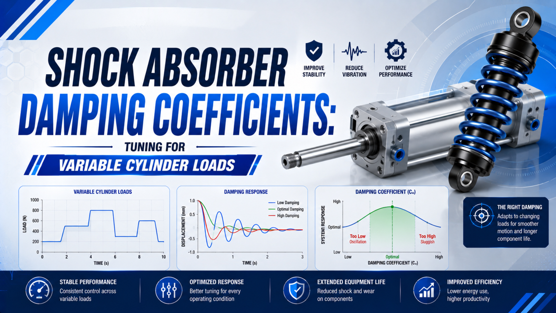
Damping coefficient is a useful model parameter, but it is not a universal dial setting for an industrial shock absorber. When a pneumatic cylinder moves variable loads, first select an absorber that covers the full energy, speed, effective-mass, and cycle-rate envelope. Then tune that exact model for smooth deceleration throughout its usable stroke.
This distinction prevents a common mistake: trying to make an undersized absorber work by turning its adjuster, even though no setting can create missing stroke or thermal capacity after the model fails its capacity check. Start with the external shock absorber sizing method, then use the commissioning process in this guide.
Key Takeaways
- ACE uses 5 application inputs for about 90% of shock absorber calculations.
- Variable-load tuning starts only after every load case fits the selected model’s limits.
- A hard initial hit and a hard end-of-stroke set-down require different corrections.
- Record validated settings by machine recipe, not by payload alone.
Damping Coefficients Are Models, Not Catalog Ratings
ACE’s calculation basis, accessed in 2026, says about 90% of applications can be screened from 5 inputs: moving mass, impact velocity, added drive force, cycles per hour, and the number of absorbers in parallel (ACE, “Calculation Bases”). A generic viscous coefficient is not one of those catalog inputs.
For an ideal linear viscous damper, force is modeled as:
Here, is damping force in newtons, is the damping coefficient in newton-seconds per metre, and is instantaneous velocity in metres per second. That approximation is useful in simulation. It does not prove that an industrial shock absorber has one constant across its stroke, speed range, temperature range, or adjustment scale.
Industrial hydraulic shock absorbers meter oil through one or more orifices to spread resisting force over the available stroke while converting mechanical energy into heat. Orifice geometry, piston position, oil behavior, internal pressure, and adjustment mechanism all affect the force curve. Adjustment setting is therefore a repeatable model-specific reference, not a calibrated universal coefficient.
Critical damping has a similarly narrow boundary. The relationship belongs to an equivalent mass-spring-damper vibration model with a defensible stiffness . An external cylinder shock absorber is normally selected from absorbed energy and manufacturer limits. Assigning it a guessed spring stiffness and then choosing a percentage of critical damping mixes two different engineering problems.
Treat the coefficient as a simulation parameter and the dial position as a commissioning record. They can be correlated only when the manufacturer supplies a force-velocity model or when instrumented testing identifies one for the exact absorber and operating point.
What Must Be Checked Before Tuning?
ACE screens shock absorbers against energy per cycle, energy per hour, effective mass, and stroke, while SMC adds the selected model’s collision-speed range (ACE, “Calculation Bases”; SMC RB Series catalog, retrieved 2026). Pass all 5 boundaries before touching the adjuster.
Start with translational kinetic energy at the instant the load contacts the absorber:
is kinetic energy in joules, is total moving mass in kilograms, and is measured or conservatively estimated impact velocity in metres per second. Include the piston, carriage, tooling, product, brackets, and any mechanism whose inertia is reflected into the stopping axis. The related moving-load kinetic energy guide explains this boundary in more detail.
If the cylinder continues to push through the absorber stroke, add propelling work:
is drive work in joules, is the net propelling force in newtons, and is the effective absorber stroke in metres. Add gravity or spring work with the correct sign when those forces act along the travel direction. Then calculate the event and continuous thermal duties:
is gravity or other external work in joules, is sustained events per second, and is average dissipated power in watts. Catalogs often express the same thermal check as energy per hour rather than watts. Keep the units visible so joules per minute are not mislabeled as watts.
Effective mass is another separate screen:
is the effective mass presented to the absorber. It can exceed the physical payload because cylinder thrust continues to add energy during deceleration. An absorber may pass its joule rating yet behave poorly if the calculated effective mass lies outside the model’s permitted range.
How Does Variable Load Change the Energy Envelope?
ACE warns that final impact velocity in an accelerating motion can be 1.5 to 2 times the average velocity, and kinetic energy rises with velocity squared (ACE, “Calculation Bases”, retrieved 2026). Checking payload mass while assuming one unchanged speed can miss the real worst case.
Build one row for every credible machine recipe. At minimum, record total moving mass, impact speed, cylinder pressure or net drive force, absorber stroke, orientation, events per hour, ambient temperature, and the proposed absorber model. The highest mass is not automatically the controlling case. For example, a 10% increase in impact speed raises kinetic energy by 21% when mass stays unchanged.
The original 2 kg to 18 kg example illustrates the mass effect when impact speed truly remains at 1.2 m/s:
| Moving mass | Impact speed | Kinetic energy | Kinetic-only average power at 45 events/min |
|---|---|---|---|
| 2 kg | 1.2 m/s | 1.44 J | 1.08 W |
| 5 kg | 1.2 m/s | 3.60 J | 2.70 W |
| 10 kg | 1.2 m/s | 7.20 J | 5.40 W |
| 15 kg | 1.2 m/s | 10.80 J | 8.10 W |
| 18 kg | 1.2 m/s | 12.96 J | 9.72 W |
For the 18 kg case, the arithmetic is and , so the kinetic-only thermal load is , not 585 W. The final selection still needs drive work, allowable event energy, hourly capacity, effective mass, and the exact impact-speed range.
A 9:1 mass range gives a 9:1 kinetic-energy range only when speed is unchanged, but it does not prove that the adjuster needs a 9:1 force range. The selected absorber’s metering profile, effective-mass window, impact-speed window, and stroke determine whether both endpoints can be decelerated smoothly.
How Should You Tune an Adjustable Shock Absorber?
Parker’s revised 2021 catalog uses a 0 to 9 adjustment scale. It instructs the installer to cycle the machine until deceleration is smooth across the stroke (Parker, “Industrial Shock Absorbers, Catalog 0900P-7”). Start only after model selection and installation checks pass.
- Make the test safe. Guard the impact zone, prevent unexpected restart, confirm the positive stop where the product requires one, and keep personnel away from the moving load. Don’t adjust a live machine unless the manufacturer’s procedure explicitly permits it.
- Verify the mechanics. Align the absorber with the impact direction, check mounting stiffness, confirm full piston return, and remove side load. A setting change can’t correct a bent bracket or an off-center carriage.
- Start from the specified initial setting. Use the factory preset or the exact series manual. A scale position from another brand or model has no transferable meaning.
- Test the worst credible energy case at controlled speed. Use a reduced commissioning rate where the manufacturer permits it. Confirm that the absorber does not bottom, overheat, stick, or exceed its return-time limit.
- Adjust in small, documented steps. Cycle the mechanism several times after each change. Look for smooth use of the working stroke rather than the shortest stopping time.
- Test the opposite endpoint. Run the minimum-load case and any light, high-speed recipe. Watch for an abrupt initial hit, rebound, chatter, or poor process settling.
- Lock and mark the accepted setting. Tighten the locknut or locking mechanism to the specified torque. Record the model, setting, load recipe, impact speed, pressure, temperature, and date.
Why test both endpoints? Because a heavy case may challenge event energy or stroke, while a light case may fall below the absorber’s effective-mass range. Intermediate recipes still need confirmation when velocity or drive pressure does not change monotonically with payload.
What Do Impact Symptoms Tell You?
Parker’s revised 2021 catalog separates 2 symptoms for its adjustable series: hard impact at the start and hard set-down at the end. Its 0 to 9 models require opposite adjustment directions for those symptoms (Parker, “Industrial Shock Absorbers, Catalog 0900P-7”). Follow the exact model’s procedure.
| Observed behavior | Likely interpretation | What to verify before adjusting |
|---|---|---|
| Sharp force at first contact | Initial resistance may be too high, or impact alignment is poor | Impact speed, side load, rod-end contact, model-specific adjustment direction |
| Hard set-down near full compression | Resistance may be too low, energy may be excessive, or usable stroke is reduced | Event energy, drive work, stop position, stroke, temperature, setting |
| Rebound after stopping | Stored energy elsewhere or unsuitable stopping sequence | Springs, pneumatic cushion overlap, structure, external stop timing |
| Smooth stop when cold, hard stop when hot | Continuous thermal duty may exceed the operating condition | Events per hour, ambient temperature, airflow around the body, catalog derating |
| Piston does not fully return | Cycle interval or return force may be inadequate | Return time, contamination, preload, orientation, manufacturer instructions |
| Different result on nominally identical stations | Installation or operating inputs are not actually identical | Alignment, speed, pressure, load center, stop position, part number, setting lock |
Don’t use noise alone as the acceptance criterion. For example, a quiet stop can still overload the guide or bracket, and a well-sized absorber does not repair an incorrect load path. Use the end-of-stroke force and energy guide when structural reaction force or stop placement is part of the decision.
If the cylinder’s internal cushioning remains active, verify that it is meant to work with the external absorber. The SMC MY1H instructions explicitly say not to use its shock absorber together with the air cushion and warn that reducing effective absorber stroke sharply reduces capacity (SMC MY1H catalog, retrieved 2026). Other series may use different arrangements.
For problems that originate inside the cylinder rather than at the external stop, use the cylinder cushion failure diagnosis guide and the pneumatic cushion needle adjustment guide.
When Is One Setting No Longer Enough?
SMC requires 3 RB-series limits: absorbed energy, corresponding mass, and collision speed. Its parallel-use rule adds a 0.6 sharing factor instead of assuming equal division (SMC RB Series catalog, retrieved 2026). No dial position can override these limits.
One setting is unacceptable when either endpoint bottoms the absorber, produces a severe initial force, falls outside the effective-mass or speed range, exceeds event or hourly energy, prevents full return, or requires a stop position that violates the product drawing. At that point, broaden the hardware envelope instead of accepting a compromise impact.
Possible remedies include selecting a different metering range, using a self-compensating model whose published effective-mass range covers all recipes, increasing usable stroke, reducing impact speed, reducing continued cylinder thrust during deceleration, or separating production recipes between two validated settings. A longer stroke often reduces average stopping force, but only the manufacturer’s model data can confirm the resulting selection.
Two absorbers in parallel may be appropriate when the load cannot be stopped centrally, but they are not a shortcut to a custom progressive curve. ACE stresses exact parallel alignment, while SMC warns that dimensional and machine differences prevent equal energy sharing. Use the selected manufacturer’s load-sharing method and inspect the supporting structure for unequal contact.
For cycle-to-cycle load changes, a machine recipe can select a previously validated setting only if the adjustment mechanism is designed for that operation and the safety controls prevent an unverified state. A manually repositioned dial is not automatic load sensing. If the load changes every cycle, a correctly selected self-compensating product or a redesigned motion profile is usually the cleaner engineering question.
A Commissioning Record That Operators Can Reuse
ACE separates 4 results: energy per cycle, energy per hour, effective mass, and stroke, while Parker then tunes for smooth deceleration (ACE, “Calculation Bases”; Parker Catalog 0900P-7). A reusable record preserves both the limits and setting.
In our experience, a dial number by itself is rarely reusable. The record becomes useful only when it carries the impact speed, load recipe, pressure, and full absorber part number that produced the accepted stop.
| Record field | Why it matters |
|---|---|
| Machine and axis | Prevents settings from migrating between unlike mechanisms |
| Absorber manufacturer and full part number | Makes the scale direction, capacity, and maintenance limits traceable |
| Payload recipe and total moving mass | Separates product mass from complete moving mass |
| Measured impact speed | Captures the squared term in kinetic energy |
| Pressure or net drive force | Preserves the propelling-work input |
| Usable absorber stroke and stop position | Detects lost capacity after mechanical changes |
| Events per hour and ambient temperature | Preserves the thermal-duty basis |
| Adjustment position and lock condition | Makes the accepted tuning repeatable |
| Observed stop behavior | Records start impact, set-down, rebound, return, and heat |
| Approver and revision date | Controls later recipe or hardware changes |
Revalidate the record after a payload, speed, pressure, stop position, guide, mounting bracket, absorber model, or cycle-rate change. Also inspect alignment whenever impact behavior changes unexpectedly. The broader actuator mounting and alignment guide explains why a damping adjustment cannot compensate for side load or structural misalignment.
One impressive dial number isn’t the goal. Instead, aim for a documented operating envelope in which every credible recipe stays inside the absorber’s capacity and produces a smooth, repeatable stop.
Shock Absorber Damping FAQs
Parker uses a model-specific 0 to 9 scale, while ACE and SMC screen energy, effective mass, velocity, and duty limits. These 4 boundaries prevent a universal coefficient-to-dial conversion (Parker Catalog 0900P-7; ACE calculation basis).
Is the damping coefficient the same as the shock absorber dial setting?
No. A damping coefficient expresses a force-velocity relationship in a mathematical model. A dial setting changes the internal metering of one absorber series. Unless the manufacturer publishes a conversion or a validated test identifies it, the scale position cannot be reported as a universal value in newton-seconds per metre.
Which load should be tuned first in a variable-load application?
Begin with the worst credible energy case under the manufacturer’s commissioning procedure, then test the opposite endpoint and intermediate cases. The heaviest payload is not always worst because impact speed and drive force may change, so use guarded tests and verify event energy, effective mass, speed range, return, and temperature before accepting the setting.
Can one adjustable shock absorber cover loads from 2 kg to 18 kg?
Possibly, but a 9:1 mass range alone cannot answer the question. Calculate every credible case using actual impact speed and drive work, then compare each result with the exact model’s event-energy, hourly-energy, effective-mass, speed, stroke, and temperature limits. Both light-load and heavy-load deceleration must pass physical commissioning tests.
Can a flow control valve replace shock absorber tuning?
No. A flow control can reduce approach speed and therefore lower kinetic energy, but it does not provide a rated stopping stroke or absorb a verified amount of energy. Use speed control to shape the motion, then size and tune the cushion or external absorber against the resulting worst-case impact conditions.
Can two shock absorbers be used in parallel for a wide load range?
They can be used when the manufacturer permits it, but don’t assume perfect 50/50 sharing, because the units must contact together, remain accurately aligned, and use the manufacturer’s derating or sharing calculation. Different dial settings are not a validated progressive-damping strategy unless the supplier has designed and approved that arrangement.
Sources and technical references
- ACE Controls, “Calculation Bases,”
https://www.acecontrols.com/us/cad-downloads/knowledge/calculation-bases-for-the-design-of-industrial-shock-absorbers.html. Supports mass, impact velocity, propelling force, cycle rate, energy, effective mass, stroke, and parallel-unit calculation inputs. Retrieved 2026-07-23. - ACE Controls, “Product Knowledge Industrial Shock Absorbers,”
https://www.acecontrols.com/us/cad-downloads/knowledge/industrial-shock-absorbers.html. Supports hydraulic energy conversion, smooth-stroke deceleration, adjustment cautions, and parallel mounting. Retrieved 2026-07-23. - Parker Hannifin, “Industrial Shock Absorbers, Linear Decelerators, Catalog 0900P-7,”
https://www.parker.com/content/dam/Parker-com/Literature/Literature-Files/pneumatic/Literature/Actuator-Cylinder/0900/0900P_Shocks_Absorber.pdf. Supports the 0 to 9 model-specific adjustment procedure and start-impact versus end-set-down diagnosis. Revised 2021; retrieved 2026-07-23. - SMC Corporation, “RB Series Shock Absorber,”
https://www.smcworld.com/catalog/en/actuator/RB-E/6-2-3-p0895-0917-rb_en/data/6-2-3-p0895-0917-rb_en.pdf. Supports absorbed-energy, corresponding-mass, collision-speed, and parallel-use limits. Retrieved 2026-07-23. - SMC Corporation, “Series MY1H Mechanically Jointed Rodless Cylinder, Linear Guide Type,”
https://ca01.smcworld.com/catalog/BEST-5-2-en/2-p1187-1209-my1h-z_en/spdfdata/2-p1187-1209-my1h-z_en_12sp.htm. Supports impact-speed measurement, effective-stroke warning, and the model-specific air-cushion interaction rule. Retrieved 2026-07-23. - ACE Stossdämpfer GmbH, “ACETips: How to adjust a shock absorber correctly,”
https://www.youtube.com/watch?v=xFyLYCfe-OE. Official adjustment demonstration. Retrieved 2026-07-23. - ACE Stossdämpfer GmbH, “ACETips: How to properly mount two ACE Shock Absorbers in parallel,”
https://www.youtube.com/watch?v=RjF3Eg6P-zA. Official parallel-mounting demonstration. Retrieved 2026-07-23.