

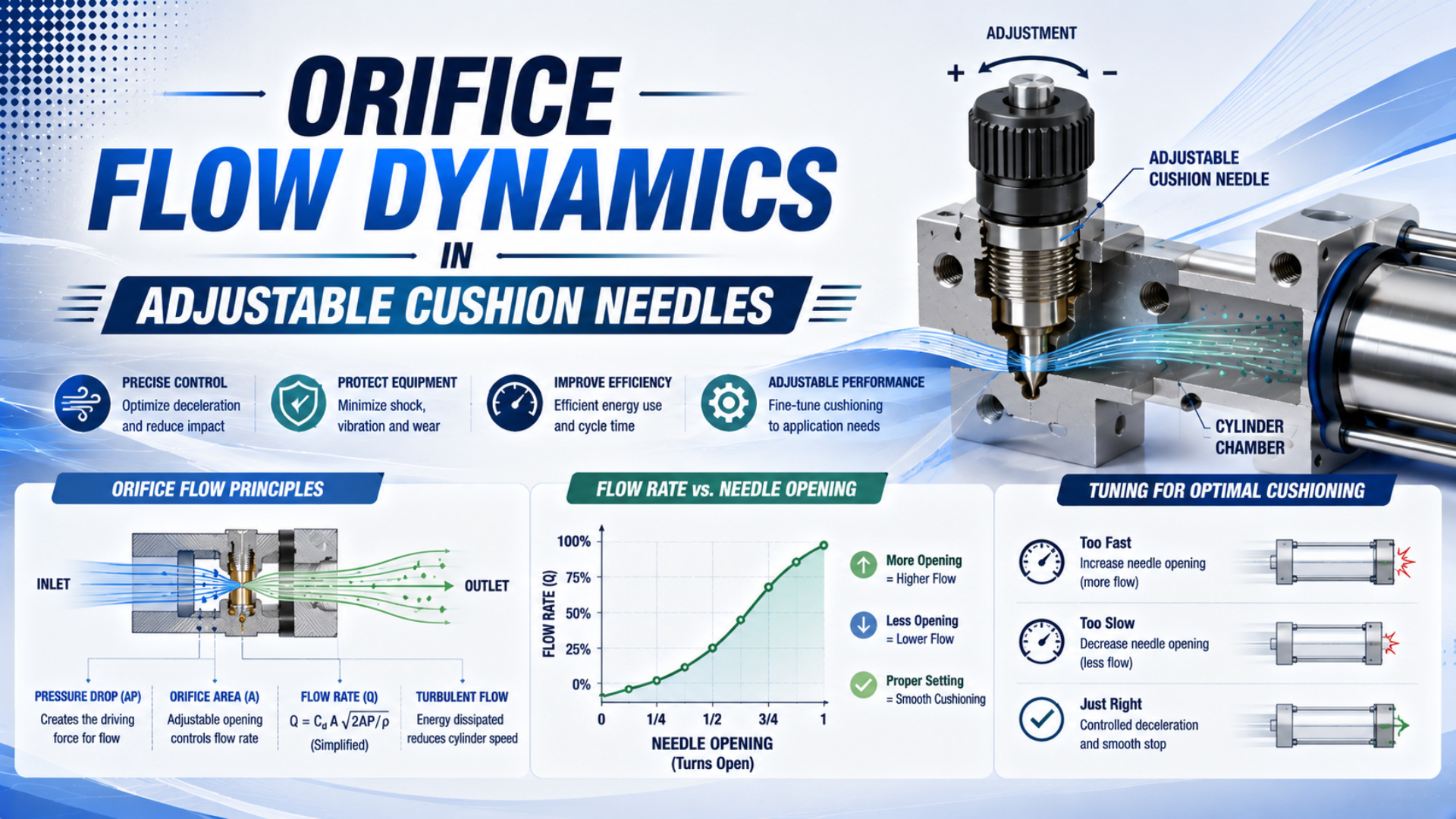
An adjustable cushion needle meters compressed air out of a shrinking cylinder end chamber. That process cannot be predicted from pressure difference alone. The useful variables are the needle’s effective area, upstream cushion pressure, downstream exhaust pressure, gas temperature, pressure ratio, chamber volume, piston speed, and the cylinder manufacturer’s energy limit.
For air with a specific-heat ratio of 1.4, an ideal orifice reaches its critical condition when downstream absolute pressure falls to about 0.528 of upstream absolute pressure. Below that ratio, lowering the downstream pressure no longer increases the ideal mass flow. The cushion pressure can still rise because the piston keeps reducing chamber volume.
Key Takeaways
- Air reaches the ideal critical-flow boundary near a 0.528 absolute pressure ratio.
- Use absolute pressure, temperature, effective area, and discharge coefficient for an orifice estimate.
- Needle turns are model-specific, not a transferable flow unit.
- Tune from measured motion and pressure after checking the manufacturer’s cushion-energy limit.
For energy screening and commissioning, use the broader pneumatic cushion needle guide. This article stays with the narrower question: what does the adjustable orifice do while the cushion chamber is being compressed?
Why Does a Cushion Needle Need a Compressible-Flow Model?
ISO 6358-1 covers steady-state testing of pneumatic components with fixed or variable internal flow paths, but it explicitly excludes cylinders and accumulators from that test method (ISO 6358-1, 2013). However, a cushion needle can be screened as a variable restriction while the moving cylinder requires a separate transient model.
An adjustable cushion needle is a variable restriction that controls mass leaving the trapped end chamber after the main exhaust closes. ISO 6358-3 treats pneumatic components and piping with subsonic and choked compressible-flow relationships, so the restriction cannot be reduced to the liquid equation . During cushioning, upstream density changes while chamber volume shrinks. For example, a reading of 7 bar gauge is approximately 8 bar absolute near sea level, and an exhaust reading of 0 bar gauge is still roughly 1 bar absolute. Therefore, pressure difference alone cannot establish the flow branch. Use upstream and downstream absolute pressure, temperature, effective area or ISO conductance, and the product-specific opening characteristic before coupling that flow result to cylinder motion.
A cushion needle therefore has two useful descriptions. The first is its steady-state flow characteristic at a fixed opening. The second is its role inside a time-varying cushion chamber. Confusing those descriptions is why a plausible orifice calculation can still predict the wrong stop.
What Changes When the Cushion Spear Enters the End Cap?
Parker’s SR-series catalog describes a check seal that blocks the normal exhaust path and forces air through the adjustable needle orifice as the cushion sleeve enters the seal (Parker SR catalog, 2026). The needle meters the remaining exhaust; it does not determine when cushioning begins.
Before engagement, the cylinder exhausts mainly through the normal port, valve, tubing, and silencer. When the cushion spear or sleeve enters its matching seal, that larger path closes. As a result, the trapped end volume must discharge through the smaller adjustable passage while the piston continues toward the end cap.
Three effects occur at once:
- Chamber volume falls as the piston advances.
- Air mass leaves through the needle-controlled restriction.
- Cushion pressure acts on the piston area and produces decelerating force.
A separate check path matters on reversal. Meanwhile, it provides a freer route for supply air so the piston can leave the end position without filling through the restricted needle. A slow breakaway from one end may therefore involve the check seal or passage, not the needle setting alone.
For a component comparison outside the cylinder, see needle valves versus one-way flow controls. A cylinder cushion needle is an integrated final-zone restriction; a meter-out speed controller shapes flow through most of the stroke.
When Does the Needle Flow Become Choked?
NASA’s ideal-gas derivation places maximum mass flow at Mach 1 in the minimum-area throat (NASA Glenn, 2021). For air with , the corresponding ideal critical downstream-to-upstream absolute pressure ratio is 0.528, derived from the isentropic relation below.
Define the absolute pressure ratio as:
Here, is upstream cushion-chamber absolute pressure and is downstream exhaust absolute pressure. The ideal critical ratio is:
For dry air near room temperature, use , which gives . Specifically, flow is subsonic in this ideal screening model when and choked when . Real passages have losses and geometry effects, so supplier conductance data or testing should replace the ideal boundary for final design.
For the subsonic branch, a common ideal-gas orifice expression is:
For the choked branch:
In these equations, is mass flow in kg/s, is the discharge coefficient, is effective area in m², is the specific gas constant, and is upstream absolute temperature in kelvins. Use for dry air.
Importantly, choking caps mass flow through the restriction at the current upstream state. It does not cap cushion pressure or decelerating force. If the piston compresses the trapped volume faster than mass can escape, upstream pressure can continue rising, and choked mass flow rises approximately in proportion to that upstream absolute pressure when area and temperature remain fixed.
For the same boundary in valves and supply paths, see the pneumatic choked-flow guide. Here the upstream side is the shrinking cushion chamber rather than the plant-air header.
Why Don’t Needle Turns Map Directly to Flow?
SMC’s current CM2 catalog warns that opening its cushion needle more than 3 turns from fully closed is effectively equivalent to no cushion, while fully closed operation can damage the cushion seal (SMC CM2 catalog, 2026). That model-specific limit disproves any universal 3-to-7-turn rule.
A turn count converts thread rotation into axial needle travel. It does not reveal seat diameter, taper, port shape, maximum lift, leakage, discharge coefficient, or the point where another internal passage becomes the limiting restriction. For example, two needles with the same thread pitch can have different useful flow curves.
In particular, near the seat, manufacturing tolerances and contamination occupy a larger fraction of the available gap. In contrast, farther open, the needle gap may stop controlling because the drilled passage, cross-hole, exhaust port, valve, fitting, tube, or silencer has become smaller in conductance. Consequently, the response may flatten, but the location of that flattening belongs to one design.
Treat the adjustment position as a repeatable commissioning coordinate, not as an airflow unit. Accordingly, record “1.25 turns from the manufacturer’s closed reference on series X” together with pressure, load, speed, and direction. Never transfer “1.25 turns” to another cylinder family without its curve or a new test.
Specifically, when procurement needs comparable data, ask for:
| Required information | Why it matters |
|---|---|
| Cylinder series, bore, stroke, and cushion option | Defines the actual internal geometry |
| Allowed adjustment range and closing torque | Prevents seat, seal, or retention damage |
| Flow or conductance versus position | Replaces generic turn-to-flow assumptions |
| Cushion stroke or engagement length | Defines the available deceleration zone |
| Allowable mass-speed or kinetic-energy data | Establishes whether tuning is sufficient |
| Operating pressure and temperature range | Bounds the gas state and component rating |
Coupled Pressure, Volume, and Piston Motion
A 2002 JFPS experiment sampled pressure, position, velocity, acceleration, and force at 2,000 samples per second while varying loads of 40, 70, and 100 kg and supplies of 4, 5, and 6 bar (Kim and Lee, 2002). That instrumentation shows why one steady flow value cannot describe cushioning.
For example, let be cushion volume, the effective cushion-side piston area, and piston velocity toward the end cap. Chamber volume changes approximately as:
If leakage and reverse inflow are neglected during the short cushion event, chamber mass changes as:
Chamber state also follows the ideal-gas relation:
Accordingly, a simplified axial force balance can be written as:
Here, is effective moving mass, is force from the opposite chamber, includes gravity or process load with its sign, is end-side reference pressure, and is friction. The equations must be solved together because motion changes volume, volume changes pressure, and pressure changes motion.
Similarly, temperature is not a decorative correction. A 2022 peer-reviewed TU Dresden model used heat transfer to calculate cushion pressure and validated the model at different supply pressures, piston speeds, and throttle openings (Nazarov and Weber, 2022). Short events can depart significantly from an isothermal assumption.
In other words, a needle-flow calculator estimates one restriction state. It cannot certify the full stop, allowable energy, peak pressure, rebound, or end-cap load without cylinder geometry and motion data.
Worked Example: What Can an Orifice Calculation Tell You?
Using NASA Glenn’s ideal choked-flow relation, a 0.60 mm opening with , 8 bar absolute upstream, 1 bar absolute downstream, and 293.15 K air gives a 0.125 pressure ratio and . That equals about 18.3 standard L/min at 15°C and 1.01325 bar.
First calculate area:
Then compare the absolute pressure ratio with the critical value:
Use the choked branch. Substituting , , , , and gives:
At the defined standard reference condition, this is approximately:
This result is a derived engineering example, not a universal cushion setting. If upstream absolute pressure rises from 8 to 12 bar while area and temperature stay fixed and flow remains choked, mass flow rises by 50% to about . In contrast, if upstream pressure falls to 1.5 bar absolute while downstream stays at 1 bar absolute, , so the subsonic branch applies. Calculated mass flow falls to , or 3.28 standard L/min. Both comparisons hold area, temperature, and discharge coefficient fixed.
What can these numbers support? Specifically, they compare candidate areas, identify the ideal flow branch, and estimate mass discharge at a measured instant. They cannot convert 0.60 mm into a needle-turn setting or prove that a moving load will stop safely.
How Should You Measure and Tune the Actual Cushion?
In the JFPS test, cushion pressures reached 8, 10, and 12 bar from respective 4, 5, and 6 bar supply tests in the meter-out configuration, with a reported 0.4 second cushion stroke time (Kim and Lee, 2002). Transient cushion pressure can therefore exceed supply pressure.
Start with the exact product manual. SMC’s CM2 instructions say not to operate fully closed, not to exceed its stated useful opening, and to open gradually while checking cylinder operation. Another series may use a different reference, direction, tool, retention feature, or limit.
Use a controlled test sequence:
- Record cylinder series, bore, stroke, cushion option, mounting, load, supply pressure, valve, tubing, silencer, and current adjustment position.
- Check moving mass and measured cushion-entry speed against the exact manufacturer cushion chart.
- Mark the starting needle position and tune one end at a time.
- Reduce speed to the manufacturer’s commissioning condition before approaching the final production state.
- Record position or end-zone time, cushion-chamber pressure, opposite-chamber pressure, and visible rebound over several cycles.
- Change the needle in small, repeatable increments permitted by the manual.
- Stop adjusting if the useful range cannot remove impact without creating rebound or a long final crawl.
Specifically, a pressure transducer at the cushion-side test point needs adequate range and response for the expected transient. Therefore, pair it with position or high-rate end-zone timing. A plant regulator gauge alone cannot show the local pressure spike after the main exhaust path closes.
For main-stroke behavior, the meter-out speed-control guide explains how the speed controller stabilizes motion before cushion engagement. If motion is unstable through the whole stroke, correct that circuit first. Do not use the cushion needle as the primary speed controller.
Use the Cylinder Cushion Energy Calculator as a screening step for moving mass, entry speed, drive force, and cushion stroke. Manufacturer energy or mass-speed data remain the acceptance limit.
Model Limits and Selection Boundary
A 2022 TU Dresden study used an 18-page thermal model rather than one algebraic orifice equation, and validated it across supply pressure, piston speed, and throttle opening (Nazarov and Weber, 2022). A simple calculator is useful for screening, not for final cushion certification.
In addition, several effects sit outside the ideal equations used above:
- The effective area and vary with needle position and Reynolds or Mach state.
- The cushion spear and seal may create leakage or a changing bypass geometry.
- Tube, fitting, valve, and silencer conductance can limit downstream flow.
- Chamber temperature changes during rapid compression and discharge.
- Seal friction, guide friction, side load, and elastic machine structure alter motion.
- The opposite chamber continues to drive or resist the piston.
- External contact or a mechanical stop may end motion before the designed cushion stroke.
Accordingly, use three escalating model levels. Start with catalog energy data for selection. Then add a steady compressible-orifice calculation to understand the restriction. Move to synchronized pressure and motion measurement, or a validated transient simulation, when peak pressure, rebound, cycle time, or end-cap load is critical.
If impact remains after the cylinder is inside its approved operating range and the needle has usable authority, follow the cylinder cushion failure diagnostic sequence. If the required energy lies outside the cylinder chart, reduce entry speed, increase available cushion capacity, or select an external shock absorber.
Cushion Needle Flow FAQs
SMC’s CM2 catalog gives a 3-turn product limit, while NASA’s ideal-gas relation yields the 0.528 critical pressure ratio for air. These figures answer different questions. The following five answers keep geometry, flow, energy, and adjustment separate so neither number is used outside its valid scope.
Can I set a cushion needle from cylinder bore and stroke alone?
No. Bore and stroke do not define needle geometry, cushion engagement length, moving mass, entry speed, downstream conductance, or allowable energy. Use the cylinder’s manual and mass-speed or energy chart first. Then tune the actual load while recording the product-specific needle reference, end-zone motion, and pressure response.
Does choked flow mean cushion pressure stops rising?
No. Choked flow means the restriction has reached its maximum ideal mass flow for the current upstream pressure, temperature, and area. The piston can still shrink the chamber faster than air escapes. Cushion pressure may continue rising, and the choked mass-flow capacity also rises as upstream absolute pressure increases.
Why can the same needle setting behave differently at two speeds?
Kinetic energy varies with speed squared, while cushion-entry speed also changes the rate at which chamber volume disappears. Doubling entry speed multiplies kinetic energy by four before considering drive force. The same opening must then discharge a faster compression event and may produce impact, rebound, or a higher pressure peak.
Should cushion-flow calculations use gauge or absolute pressure?
Use absolute pressure for pressure ratios, density, and compressible-flow equations. Gauge pressure is useful for ordinary machine readings, but zero gauge pressure is still approximately one atmosphere absolute. Record both the gauge reading and the atmospheric reference when converting test data, especially when comparing different sites or elevations.
When should I use an external shock absorber instead?
Use an external absorber or another motion strategy when calculated moving energy exceeds the cylinder’s published cushion envelope, the payload or speed range is too wide for one stable setting, or tuning cannot eliminate impact without rebound or slow final travel. Confirm mounting, alignment, stroke, energy per cycle, and temperature limits separately.
Sources and technical references
- ISO 6358-1:2013, steady-state flow characteristics of pneumatic components. Retrieved 2026-07-23.
- ISO 6358-3:2014, system calculations for subsonic and choked compressible flow. Retrieved 2026-07-23.
- NASA Glenn, Mass Flow Choking. Retrieved 2026-07-23.
- SMC CM2 Series Air Cylinder Catalog. Retrieved 2026-07-23.
- Parker Catalog 0900P-7, Round Body Pneumatic Cylinders. Retrieved 2026-07-23.
- Kim and Lee, An Experimental Study on the Cushioning Characteristics of Pneumatic Cylinder System. Retrieved 2026-07-23.
- Nazarov and Weber, Heat Transfer Model of Pneumatic End-Position Cylinder Cushioning. Retrieved 2026-07-23.