

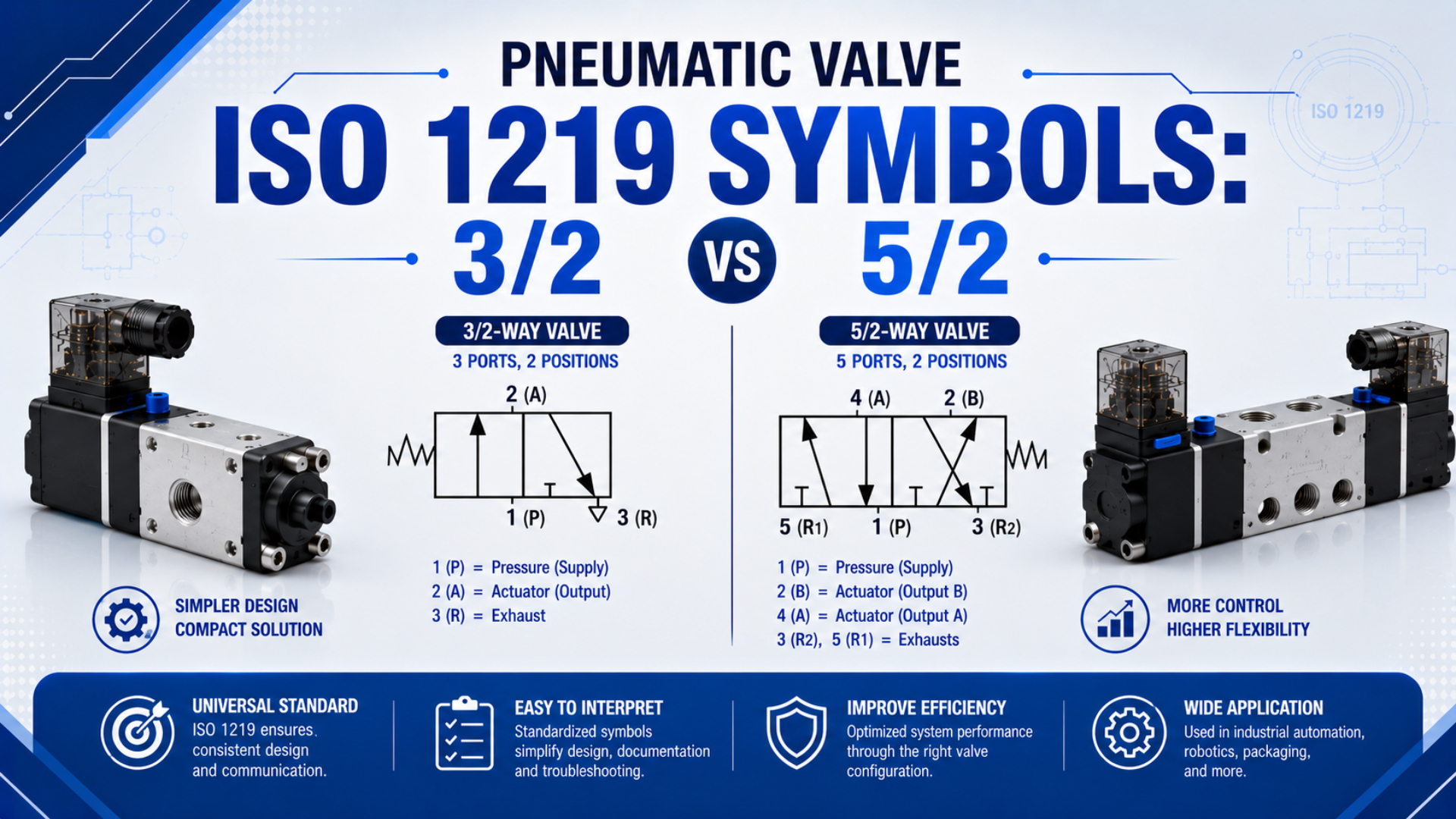
A 3/2 valve symbol represents three ports and two switching positions. A 5/2 symbol represents five ports and two positions. That notation tells you how many external flow connections and discrete states the valve has, but it does not tell you the normal state, actuator type, flow capacity, or failure behavior by itself.
ISO 1219-1 defines the building blocks and rules used to construct fluid-power symbols, while ISO 1219-2 covers their use in circuit diagrams. To read a directional valve correctly, examine each position box, trace every flow path, identify the operating symbols at both ends, and then create a simple state table.
Key Takeaways
- In 3/2 and 5/2 notation, the first number counts ports and the second counts positions.
- Arrows show connected flow paths; capped lines show blocked paths.
- The spring side, not a universal left-or-right rule, identifies a spring-return state.
- Confirm port markings under ISO 11727 and the valve datasheet before connecting tubing.
What Do 3/2 and 5/2 Mean on a Pneumatic Valve Symbol?
A 3/2 valve has 3 ports and 2 positions; a 5/2 valve has 5 ports and 2 positions. Parker’s ISO 1219 guide lists both normally open and normally closed 3/2 functions, confirming that slash notation defines port and position counts, not the rest state (Parker).
Read the designation as ports/positions:
| Designation | External ports | Switching positions | Typical controlled work ports |
|---|---|---|---|
| 3/2 | 3 | 2 | 1 |
| 5/2 | 5 | 2 | 2 |
The boxes in the symbol represent possible spool or poppet states, not separate valves. A two-position symbol therefore contains two adjacent state boxes. A 5/3 valve has the same five main ports as a 5/2 valve but adds a third, center position. The center connections must be read separately, as explained in our guide to 3-position valve center conditions.
The notation also says nothing about the valve’s physical size. Two 5/2 valves can have different port threads, flow ratings, pilot-pressure limits, seal materials, manual overrides, or manifold interfaces. Use the symbol to understand function, then use the datasheet to select hardware.
How Should You Read the Position Boxes, Arrows, and Blocked Paths?
ISO 1219-1 establishes symbol elements and rules for fluid-power components, and ISO 1219-2 applies those symbols to complete circuit diagrams (ISO 1219-1; ISO 1219-2). For a two-position valve, read one box at a time and ignore the neighboring box until every port in the first state has been accounted for.
Use this sequence:
- Count the boxes. Two adjacent boxes mean two switching positions.
- Count the external main-port lines. Do not count pilot lines, drain lines, or electrical leads as main flow ports.
- Trace arrows inside one box. An arrow connects the ports at its two ends and indicates the intended flow direction.
- Find capped or T-shaped ends. These indicate a blocked path in that position.
- Repeat for the other box. Never combine arrows from two boxes into one imaginary flow state.
- Read the operators at both ends. Springs, solenoids, pilots, pushbuttons, rollers, or detents explain how the valve changes state.
In our experience, the safest mental model is a truth table, not a picture of a moving spool. Write a row for each position and record which ports connect and which are blocked. This method works even when the symbol is rotated, embedded in a manifold drawing, or shown without familiar P, A, B, R, and S letters.
Parallel internal lines without arrowheads may be used when flow direction is not specified. A crossover does not automatically mean two paths connect at the crossing. Follow the line endpoints and junction marks used by the drawing, then verify the component legend when the reproduction is unclear.
Which Port Numbers and Letter Codes Should You Expect?
ISO 11727 covers identification and marking rules for main-flow, control, pilot-supply, and solenoid connections on pneumatic control valves (ISO 11727). In the common numeric convention, port 1 is pressure supply, ports 2 and 4 are work connections, and ports 3 and 5 are exhausts; letters may appear beside those numbers.
| Port | Common letter | Function in typical directional-valve diagrams |
|---|---|---|
| 1 | P | Main pressure supply |
| 2 | A | First work or actuator port |
| 3 | R or EA | Exhaust associated with work port 2 |
| 4 | B | Second work or actuator port |
| 5 | S or EB | Exhaust associated with work port 4 |
| 12, 14 | Pilot/control designations | Pneumatic signals that shift the valve |
From our analysis of manufacturer drawings, letter conventions vary more often than the basic numeric pattern. Treat numeric and alphabetic labels as cross-checks, not substitutes for tracing the symbol. ISO 5599-1 does include port identification for a specific family of five-port mounting interfaces, but its main scope is the interface surface, not the complete graphical language of every pneumatic valve (ISO 5599-1).
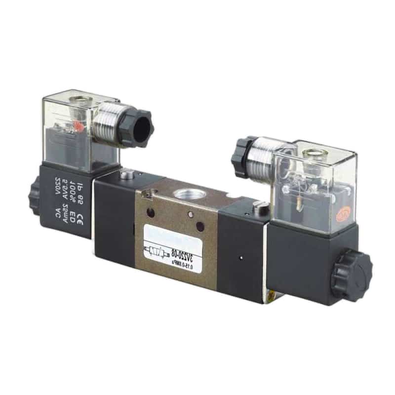
A physical valve may hide several ports underneath or on a manifold. Read the printed function symbol and molded port markings before connecting tubing.
The symbol beside a solenoid is an operating method, not another air port. The same applies to a spring or manual override. If a drawing shows dashed pilot lines leading to 12 or 14, follow those signal paths separately from the main flow through ports 1, 2, 3, 4, and 5.
How Do You Identify the Rest State of a 3/2 or 5/2 Valve?
A two-position valve has 2 state boxes, but their left-to-right order does not create a universal normal-position rule. For a spring-return valve, the box immediately adjoining the spring represents the spring-return state when the opposing operator is released. Confirm that box’s internal paths and the complete operator arrangement on the manufacturer’s symbol.
For a single-solenoid, spring-return valve, locate the solenoid on one end and the spring on the other. Energizing the coil shifts the valve against the spring. Removing the electrical signal allows the spring to return it. The symbol’s port lines remain fixed while the internal state boxes conceptually move into alignment.
A double-solenoid or double-piloted valve can be bistable. One signal shifts it to one state and the opposite signal shifts it back. Removing both signals may leave the spool in its last selected state, so calling either box “normally open” or “normally closed” can be misleading without a defined initial condition. Festo catalogs distinguish monostable and bistable 5/2 functions for this reason (Festo VUVG, accessed 2026-07-23).
Detented manual valves require the same caution. Their handle position, not loss of electrical power, determines the selected state. A pilot-operated valve may also need minimum pilot or main pressure before the drawn switching action is physically available. Check the pilot-operated valve working principle when a dashed control path appears.
The 3/2 Valve State Table
A 3/2 valve has 3 main ports and 2 possible flow states. Parker’s ISO symbol guide shows both normally closed and normally open versions, so the designation must be paired with the internal paths and return operator (Parker).
For a spring-return, normally closed 3/2 valve, a typical state table is:
| State | Connected path | Blocked port | Result at work port 2 |
|---|---|---|---|
| Spring-return state | 2 to 3 | 1 | Work port exhausts |
| Actuated state | 1 to 2 | 3 | Work port pressurizes |
For a spring-return, normally open 3/2 valve, the paths reverse:
| State | Connected path | Blocked port | Result at work port 2 |
|---|---|---|---|
| Spring-return state | 1 to 2 | 3 | Work port pressurizes |
| Actuated state | 2 to 3 | 1 | Work port exhausts |
“Normally closed” means the pressure supply is closed to the work port in the defined normal state. It does not mean that all three ports are blocked. In the common NC function, the work port still connects to exhaust so a downstream chamber or pilot line can vent.
This distinction catches a frequent drawing error: checking only whether 1 connects to 2. Always record the exhaust state as well. A trapped work port and a vented work port behave very differently after the supply path closes, especially in pilot circuits, vacuum applications, and spring-return actuators.
The 5/2 Valve State Table
A 5/2 valve has 5 ports and 2 positions. In each position, supply port 1 normally connects to one work port while the other work port exhausts. Parker notes that the two exhausts can be restricted independently, which helps identify muffler and meter-out connections (Parker).
A common 5/2 state table is:
| Symbol position | Pressure path | Exhaust path | Other exhaust |
|---|---|---|---|
| Position A | 1 to 2 | 4 to 5 | 3 blocked |
| Position B | 1 to 4 | 2 to 3 | 5 blocked |
The letters A and B here are neutral state names, not a claim that Position A is always the normal state. A spring, solenoid, pilot, or detent determines how the physical valve enters and leaves those states.
Do not infer cylinder speed or force from this table. The symbol shows connectivity, not Cv, sonic conductance, pressure drop, exhaust back pressure, tube size, or actuator area. In a single-rod cylinder, retracting area is smaller than the full piston area, so equal supply pressure does not create equal extend and retract force. For application selection, use the separate 3/2 vs. 5/2 solenoid valve comparison.
How Should the Valve Symbol Be Matched to the Actuator?
A typical single-acting cylinder exposes 1 controlled air port, while a double-acting cylinder exposes 2 working ports. That makes 3/2 and 5/2 valves common matches, respectively, but the complete circuit still decides suitability. Festo describes 3/2 ports as supply, output, and exhaust, with 5/2 valves providing the paths needed for fully pneumatic bidirectional motion (Festo).
Use these checks before accepting the match:
- Actuator connections: Confirm whether the actuator has one working port, two working ports, or auxiliary ports for locks, brakes, or cushions.
- Required states: Define pressurized, exhausted, and trapped conditions for every chamber.
- Return method: Identify spring return, gravity return, powered return, detent, or an external mechanism.
- Loss-of-signal behavior: Evaluate loss of power, pilot air, and main air separately.
- Flow requirement: Confirm valve rating, pressure drop, tube ID, fittings, silencers, and required stroke time.
- Interface: Check manifold pattern, port threads, voltage, connector, manual override, and approved mounting orientation.
Count actuator work ports only as a first filter. A two-port double-acting cylinder may require a 5/3 valve when the control sequence needs a defined center condition. Conversely, specialized circuits can use paired 3/2 valves to control two chambers independently. The circuit’s state requirements outrank the component-count shortcut.
If the design must hold a cylinder between end positions, read our guide to 5-way, 3-position valves for position holding. Pneumatic compressibility, leakage, load direction, and center condition mean that a directional valve alone should not be treated as a safety-rated mechanical lock.
Which Symbol-Reading Mistakes Cause the Most Trouble?
ISO 4414 addresses significant hazards across pneumatic system design, installation, operation, and maintenance, rather than declaring a circuit safe from one valve symbol (ISO 4414). A 3/2 or 5/2 designation contains only 2 counts, so safety behavior, flow performance, and signal-loss response must all be established outside the slash notation.
Avoid these mistakes:
- Assuming the left box is always normal. Use the return and actuation symbols.
- Combining both position boxes. Only one state box describes the active internal paths at a time.
- Counting pilots as main ports. Dashed control connections are not part of the 3 or 5 main-port count.
- Ignoring blocked paths. A capped line can be as important as an arrow.
- Treating letters as universal. Confirm the numeric markings and manufacturer legend.
- Assuming a double-solenoid valve returns on power loss. A bistable spool may remain in its last selected state.
- Using the symbol as a performance rating. It does not state flow capacity, response time, leakage, or pressure range.
- Calling spring return automatically fail-safe. The resulting actuator motion must be checked against the machine risk assessment.
- Plugging unused 5/2 ports without approval. A particular valve may support conversion, but internal paths, exhausts, pilot supply, and manifold design must be verified in its documentation.
In our experience, turning the drawing into a two-row state table before ordering catches more errors than identifying the valve by body shape or connector count. Compare that table with the printed valve symbol or datasheet, then verify coil and pilot requirements using the pneumatic solenoid valve working guide.
Pneumatic Valve ISO 1219 Symbol FAQs
ISO 1219 divides the subject into symbol construction and circuit-diagram use, while ISO 11727 separately covers pneumatic port and control-mechanism identification. Those 3 references explain why slash notation, flow paths, and terminal markings must be checked together. The questions below address the symbol-reading shortcuts most likely to produce a wrong state table.
Does the left box always show the normal valve position?
No. A two-position symbol has 2 adjacent state boxes, but left and right do not define a universal normal state. For a spring-return valve, use the spring and opposing actuator symbols to identify the returned state. For a bistable double-solenoid or double-piloted valve, the last commanded position may remain selected.
Can a 5/2 valve always replace a 3/2 valve?
No. A 5/2 valve has 2 additional main ports, but plugging or ignoring them is safe only when the manufacturer’s documentation approves the exact conversion. Internal pilot supply, exhaust paths, manifold galleries, back pressure, and the required normal state can make an improvised conversion malfunction or create unexpected motion.
What do arrows and T-shaped ends mean in the symbol?
Within 1 position box, an arrow shows a connected flow path and its intended direction. A T-shaped or capped end shows that path is blocked in that state. Trace every main port to either a connection or a block before moving to the next box; do not combine paths from both positions.
Is a 5/2 valve always used with a double-acting cylinder?
A 5/2 valve is the common choice because its 2 work ports can alternately pressurize the 2 chambers of a double-acting actuator. It is not an automatic selection. Required flow, failure behavior, pilot pressure, manifold interface, exhaust control, and any need for a center state still have to be checked.
What is the symbol difference between a 5/2 and a 5/3 valve?
Both functions have 5 main ports. A 5/2 symbol has 2 position boxes, while a 5/3 symbol has 3. The middle box of a 5/3 symbol defines the center condition, such as closed center, exhaust center, or pressure center, and materially changes actuator behavior when neither end operator is active.
Sources and technical references
- ISO 1219-1:2012, graphical symbol elements and rules for fluid-power components; Amendment 1 published in 2016. Accessed 2026-07-23.
- ISO 1219-2:2012, rules for hydraulic and pneumatic circuit diagrams; confirmed current in 2023. Accessed 2026-07-23.
- ISO 11727:1999, identification of pneumatic valve ports, control mechanisms, pilot supplies, and solenoid leads; confirmed current in 2026. Accessed 2026-07-23.
- ISO 5599-1:2001, five-port directional-valve mounting interfaces without an electrical connector; confirmed current in 2024. Accessed 2026-07-23.
- ISO 4414:2010, general rules and safety requirements for pneumatic systems and components. Accessed 2026-07-23.
- Parker Pneumatic Symbols Guide, ISO 1219 valve-function examples for 3/2, 5/2, and 5/3 symbols. Accessed 2026-07-23.
- Festo: Pneumatic Valves, manufacturer explanation of 3/2 and 5/2 port functions and common operations. Accessed 2026-07-23.
- Festo VUVG Solenoid Valves, manufacturer catalog distinguishing monostable and bistable 5/2 valve functions. Accessed 2026-07-23.
- AutomationDirect: Understanding Pneumatic Valve Ports and Ways, video reference for port and position notation. Accessed 2026-07-23.