

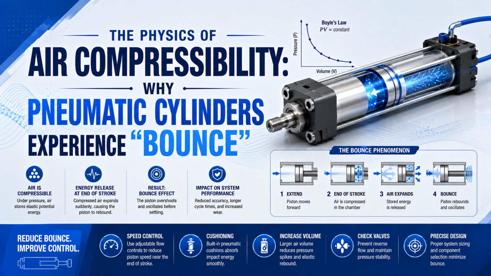
Pneumatic cylinder bounce is a visible reversal, impact, or decaying oscillation near a commanded stop. Compressed air can behave like a spring, but air compressibility is only one possible cause. Excess kinetic energy, incorrect cushion adjustment, control-loop hunting, seal friction, mechanical compliance, and an external stop can produce similar motion.
The correct remedy therefore starts with the motion signature and pressure traces, not with a universal cushion setting. This guide concentrates on end-of-stroke rebound and ringing. For the broader effects of compressibility on force, speed, and positioning, see our pneumatic cylinder compressibility guide. For component-level protection and cushion-capacity selection, use the separate pneumatic air cushioning guide.
Key Takeaways
- SMC RLQ model-specific allowable kinetic energy spans 0.15 to 0.77 J; never transfer limits across cylinder families (SMC RLQ, p. 887).
- Doubling impact speed quadruples kinetic energy, so reducing speed near the end of stroke often has the greatest effect.
- Diagnose hard impact, air-spring ringing, control hunting, and stick-slip separately because each needs a different correction.
What Does “Bounce” Mean in a Pneumatic Cylinder?
An experimental study of pneumatic end cushioning found shock and vibration at both end points and showed that load and supply pressure change cushion behavior. That evidence supports a practical definition: “bounce” describes an observed motion pattern, not a single component fault or one universal air-spring frequency (Kagawa et al., 2002).
Use the timing and location of the motion to separate four common patterns:
| Motion signature | Most likely mechanism | First evidence to collect |
|---|---|---|
| A sharp impact followed by one reversal at the stroke end | Remaining kinetic energy exceeds the installed cushion or stop capacity | Impact speed, moving mass, cushion setting, end-cap pressure |
| Several decaying cycles after the valve command | Trapped-air stiffness interacting with moving mass and damping | Position and both chamber pressures on the same time base |
| Repeated correction while a closed-loop command remains active | Control hunting, delay, deadband, or excessive gain | Command, feedback, valve output, position error |
| Jerky low-speed motion before the stroke end | Seal friction or stick-slip, sometimes combined with poor meter-out control | Low-speed position, velocity, chamber pressure, lubrication condition |
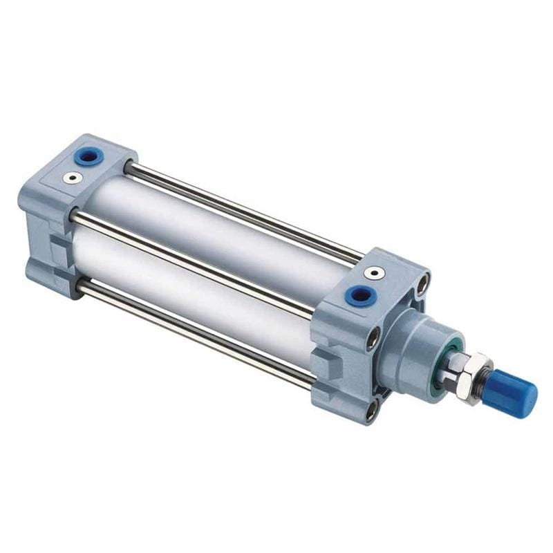
The cylinder body alone does not determine stopping behavior. Moving mass, speed, pressure, valve and tubing flow, mounting stiffness, and the selected cushion option all matter.
The Trapped-Air Spring Behind Cylinder Ringing
For dry air, NASA gives a specific gas constant of approximately 287 J/(kg K). A trapped cylinder chamber therefore changes pressure as its volume changes. Over a fast, small displacement, heat transfer may be limited, so the effective pressure-volume exponent and the trapped dead volume become central modeling assumptions (NASA).
A simple polytropic approximation is:
where is absolute pressure, is trapped volume, is the effective polytropic exponent, and is constant for the modeled compression or expansion. The relation is a local model, not a promise that every cylinder follows one fixed exponent throughout a cycle.
For a double-acting cylinder near an operating point, the small-signal pneumatic stiffness can be approximated as:
Here, and are absolute chamber pressures, and are the effective piston areas, and and include cylinder dead volume plus connected trapped volume. The expression assumes small motion, locally constant , closed mass in each chamber, and negligible valve flow during the oscillation.
The corresponding undamped natural frequency estimate is:
combines pneumatic and mechanical stiffness, while includes the piston, attached tooling, and reflected moving mass. Seal friction, valve flow, cushioning, structure, and temperature add damping and nonlinearity, so this equation is best used to explain trends rather than predict an exact field frequency.
The volumes change with piston position. A 2015 study of double-acting cylinder stiffness also highlights the influence of chamber pressure, seal behavior, and dead volume, which is why one “spring rate” cannot represent an entire stroke (Gyeviki et al.).
Why might the same cylinder settle differently after a tubing change? The added trapped volume changes pneumatic stiffness and delays the pressure response, even though the bore, payload, and regulator setting are unchanged.
From our analysis of the two-chamber model, adding downstream tubing volume does not automatically cure bounce. More trapped volume reduces local pneumatic stiffness, but it can also add transport delay and stored air. The observed frequency may fall while position settling becomes slower. Treat hose length as part of the plant, not as a damping adjustment.
Why Does Speed Dominate End-of-Stroke Impact?
Parker recommends cushioning for full-stroke cylinder applications above 4 in/s, approximately 0.1 m/s, and bases its horizontal-load energy method on kinetic energy. Because velocity is squared, a speed change has a much larger effect on impact energy than the same percentage change in moving mass (Parker, pp. C87-C88).
For a horizontal translating mass:
is kinetic energy in joules, is total moving mass in kilograms, and is piston speed immediately before deceleration in metres per second. The formula assumes translational motion. Include reflected rotational inertia when the cylinder drives rotating machinery.
Doubling while holding constant multiplies by four. That is why a cylinder that stops cleanly during setup can strike hard after a flow adjustment that appears modest.
Kinetic energy is not always the complete stopping demand. Cylinder thrust may continue doing work while the cushion or shock absorber decelerates the load:
is the net drive force acting through deceleration distance . represents gravitational work and is positive when gravity drives the moving mass into the stop. For vertical or inclined motion, follow the cylinder or shock-absorber manufacturer’s specified method because orientation can add or subtract energy.
How Does Adjustable Air Cushioning Stop the Piston?
SMC’s RLQ series illustrates why cushion data must stay model-specific: its published allowable kinetic energy spans 0.15 to 0.77 J across 32 to 63 mm bores, with a specified piston-speed range of 50 to 500 mm/s. Those values cannot be transferred to another cylinder family (SMC RLQ, pp. 887-889).
Near the end of stroke, a cushion spear or sleeve restricts the normal exhaust path. The remaining air is forced through an adjustable needle, chamber pressure rises, and the pressure force decelerates the piston over the available cushion length. The setting must slow the moving mass without creating an excessive pressure spike or preventing full stroke.
Festo describes adjustable pneumatic cushioning as one of three common approaches, alongside elastic cushioning and self-adjusting pneumatic cushioning. Its selection guidance ties the setting to mass, speed, acceleration, deceleration, operating pressure, and cylinder resistance (Festo).
An external stopper can bypass the intended cushion travel. SMC specifically requires the RLQ piston to operate to the end of its stroke for the built-in cushion to work as specified. If the machine stop arrests the carriage first, the cylinder cushion may never enter its effective deceleration phase.
For a closer look at the internal transition from free exhaust to restricted cushion flow, see our guide to the cushion seal in adjustable pneumatic cushioning.
How Should You Read Three Cushion-Setting Signatures?
Parker’s published cushion charts show the sensitivity to speed: for applications from 0.3 to 0.5 m/s, it instructs users to reduce the chart’s allowable energy by 25 percent. It also flags very low-speed heavy loads and speeds above 0.5 m/s for special review (Parker, p. C88).
| Setting condition | Typical observation | Primary risk | Corrective direction |
|---|---|---|---|
| Needle too open | High impact speed and hard end contact | Noise, rebound, damaged seals, mounts, or tooling | Close in small increments only after verifying energy is within the model limit |
| Properly adjusted | Controlled deceleration and full stroke | Hidden margin loss if only one load or pressure was tested | Validate minimum and maximum operating cases |
| Needle too closed | Slow final travel, pressure spike, or incomplete stroke | Cycle-time loss, stalling, heat, unstable end behavior | Reopen gradually according to the manufacturer’s start-up procedure |
SMC instructs users to begin the RLQ adjustment with the cushion needle fully closed and then open it gradually. Follow the procedure for the exact cylinder; do not assume this direction or starting position applies to every cushion design.
How Do You Diagnose the Actual Source of Bounce?
A 2026 experimental stick-slip study measured piston position, velocity, both chamber pressures, and friction force. That measurement set is useful beyond stick-slip because it separates a pressure-driven reversal from controller hunting or mechanical friction. A slow phone video alone cannot reliably assign the cause (Li et al., 2026).
Use a controlled diagnostic sequence:
- Make the machine safe. Isolate personnel from the motion envelope and follow the machine’s lockout, guarding, and test procedures.
- Define the event. Record whether the motion occurs at the physical end cap, an external stop, or an intermediate commanded position.
- Measure actual speed. Use position data immediately before deceleration, not average stroke speed.
- Trend both chamber pressures. Measure close enough to the cylinder and with sufficient response to capture the transient.
- Record command and feedback. For proportional or servo systems, align valve command, controller error, and measured position on one time base.
- Change one factor at a time. Reduce speed, adjust the cushion, or change the controller only after saving a baseline trace.
- Repeat at operating extremes. Test the approved maximum mass and speed, minimum dynamic supply pressure, relevant orientations, and stabilized temperature.
Read the traces together. A hard end impact with high incoming velocity suggests an energy or cushion-capacity problem. Pressure and position oscillating after flow is cut off suggest trapped-air ringing. Repeated valve commands that precede each reversal suggest hunting. Jerky motion before the end, especially at low speed, points toward friction, alignment, or meter-out instability.
A static regulator gauge can look normal while the end pressure transient is unacceptable. Cushion diagnosis needs dynamic pressure at the actuator and time-synchronized motion data. Otherwise, a supply restriction, an exhaust restriction, and a cushion adjustment can all be mistaken for one another.
Practical Changes That Reduce Bounce Without Creating a New Fault
Festo’s CRDNG documentation covers 32 to 125 mm bores and states that end cushioning reduces kinetic energy, vibration, and noise. That evidence supports a safe sequence: reduce incoming energy first, tune the installed deceleration device second, then verify the full operating range (Festo CRDNG, pp. 2, 12).
- Reduce speed before the cushion zone. A lower entry speed cuts kinetic energy with the square of velocity. Verify that the new motion profile still meets cycle requirements.
- Use stable meter-out control. Metering exhaust generally gives a compressive load better speed stability than unrestricted exhaust. See the meter-out cylinder speed-control guide.
- Tune the built-in cushion by the exact manual. Adjustment direction, starting position, allowable energy, and pressure limits are model-specific.
- Keep the intended cushion travel available. A machine stop placed ahead of the cushion engagement point can defeat built-in cushioning.
- Reduce moving mass where practical. Include the piston, rod or carriage, tooling, payload, and reflected mechanism mass in the energy estimate.
- Check valve, tubing, fittings, and silencers. Restrictions and excess trapped volume change both travel speed and transient pressure.
- Use an external industrial shock absorber when needed. High energy, short cylinder cushion travel, or a critical machine stop may require a separately sized device. Follow our external shock absorber sizing guide and verify the exact manufacturer’s limits.
- Correct alignment and guidance. Side load and binding increase friction, create stick-slip, and can make a pressure adjustment appear to fix a mechanical fault only temporarily.
Parker’s rodless-cylinder instructions list incorrect cushion setting and overload among the causes of an excessively hard end impact, and they identify an external shock absorber as one possible response. This is a troubleshooting direction, not permission to install an uncalculated stop device (Parker OSP-P).
When Does Feedback Control Make Sense?
Festo identifies three essential elements in a servo-pneumatic positioning system: a cylinder with displacement encoder, a proportional directional valve, and a position controller. Closed-loop control can command intermediate positions, but it does not remove pneumatic compliance or excuse an undersized stopping system (Festo).
Valve dynamics, sensor quality, controller timing, friction, load variation, and trapped volume become part of the loop. A mechanical end-impact problem should be corrected before controller tuning is used to mask it.
Use feedback control when the position requirement cannot be met by end stops and binary valves, and when the system has a compatible proportional valve, continuous position sensor, controller, and commissioning method. Define accuracy, repeatability, settling time, overshoot, payload, speed, pressure, and disturbance conditions before selecting hardware.
During tuning, separate three events:
- Commanded deceleration begins before the target and reduces kinetic energy.
- Pneumatic or mechanical ringing continues after the valve command stops changing.
- Controller hunting contains new corrective valve commands that sustain the motion.
If the position trace oscillates, reduce the test risk before changing gain. Confirm sensor scaling and polarity, check actuator friction and end cushioning, measure dynamic pressure, and verify that the valve is not saturating or operating inside a large deadband. Control settings from another bore, stroke, tube length, payload, or valve are not transferable defaults.
The proportional valve and cylinder PID tuning guide explains the control-side checks in more detail. Use it only after the mechanical stop, cushion capacity, and sensor installation have been verified.
Cylinder Bounce FAQs
SMC’s 32 to 63 mm RLQ cylinders alone span 0.15 to 0.77 J of allowable kinetic energy, demonstrating why a generic yes-or-no answer can mislead. These questions give diagnostic boundaries; the selected cylinder, cushion, shock absorber, valve, and controller documentation remains the authority for final settings and limits.
Is every end-of-stroke impact caused by air compressibility?
No. Compressed air contributes spring-like behavior, but a hard stop may primarily result from excessive entry speed, insufficient cushion capacity, an external stop that bypasses cushion travel, overload, alignment error, or a damaged component. Measure speed, position, and both chamber pressures before deciding that compressibility is the root cause.
Will lowering pressure always reduce bounce?
No. Lower pressure may reduce drive force and work during deceleration, but it also changes available force, acceleration, chamber stiffness, exhaust behavior, and the risk of stalling before full stroke. Test dynamic pressure at the cylinder. Do not reduce pressure below the machine’s verified force and safety requirement merely to soften an impact.
Can a flow-control valve replace cylinder cushioning?
Not automatically. A meter-out valve can control approach speed and therefore reduce kinetic energy, while a cylinder cushion provides deceleration over a defined end zone. Either device can be inadequate if the mass, speed, pressure, exhaust path, or energy exceeds its rating. Treat speed control and energy absorption as linked but separate checks.
How do I know when an external shock absorber is required?
Consider one when calculated stopping energy exceeds the built-in cushion limit, the available cushion stroke is too short, the stop must be tightly controlled, or the cylinder manual directs its use. Size it for kinetic energy, continued drive work, gravity, cycle rate, temperature, reaction force, mounting strength, and the exact supplier’s capacity data.
Does a rodless cylinder bounce less than a rod cylinder?
Not by architecture alone. Rodless construction changes packaging, moving components, guidance, and load moments, but stopping behavior still depends on total moving mass, speed, pressure, cushion design, external stops, structure, and adjustment. Compare model-specific allowable energy and cushion data rather than assuming that the absence of a projecting rod prevents rebound.
Sources
- NASA, Equation of State - Ideal Gas, gas-law variables and dry-air specific gas constant. Retrieved 2026-07-22.
- Festo, CRDNG Double-Acting Cylinder Documentation, adjustable end cushioning purpose, configuration, and operating data. Retrieved 2026-07-22.
- Festo, Cylinder Cushioning: The Three Most Common Methods, elastic, adjustable, and self-adjusting cushioning. Retrieved 2026-07-22.
- Festo, Servo-Pneumatic Positioning Systems, displacement encoder, proportional directional valve, and position-controller architecture. Retrieved 2026-07-22.
- SMC, RLQ/RDLQ Series Catalog, allowable kinetic energy, piston speed, cushion adjustment, and stroke-end requirements. Retrieved 2026-07-22.
- Parker Schrader Bellows, Pneumatic Cylinder Catalog, cushioning recommendations, kinetic-energy calculation, and speed corrections. Retrieved 2026-07-22.
- Kagawa et al., An Experimental Study on the Cushioning Characteristics of Pneumatic Cylinder System, experimental effects of load and supply pressure on cushion behavior. Retrieved 2026-07-22.
- Gyeviki et al., Increasing of Stiffness of Double-Acting Pneumatic Cylinder, cylinder stiffness, chamber pressure, dead volume, and seal effects. Retrieved 2026-07-22.
- Li et al., Experimental and System-Level Simulation Study of Stick-Slip Characteristics in Pneumatic Cylinders, synchronized position, velocity, chamber-pressure, and friction measurements. Retrieved 2026-07-22.
- Parker, OSP-P Pneumatic Rodless Cylinder Operating Instructions, hard end-impact troubleshooting and external shock-absorber direction. Retrieved 2026-07-22.