

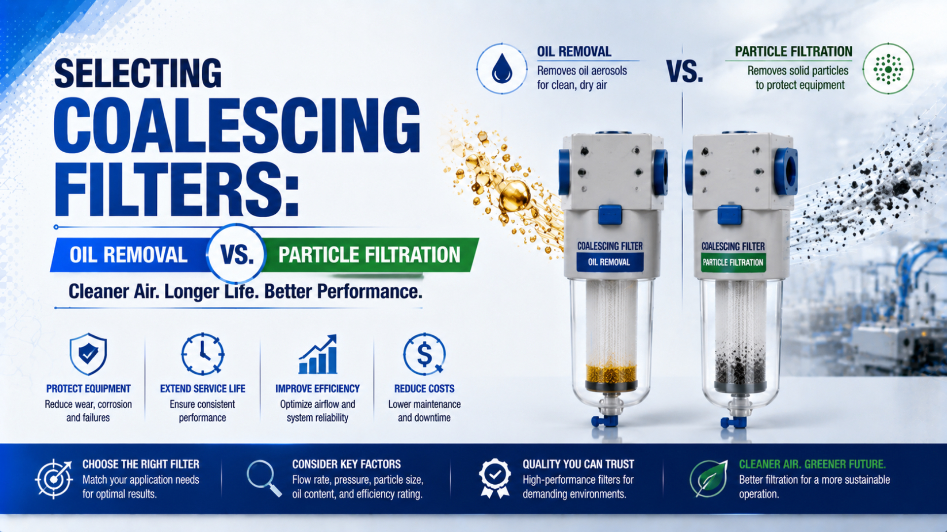
A particle filter and a coalescing filter aren’t interchangeable. Particle performance is normally specified by particle-size bands, counts, mass concentration, or a tested efficiency. Coalescing performance is normally specified by outlet oil-aerosol concentration under stated test conditions. ISO 8573-1 makes another distinction: its oil class covers total oil, including liquid, aerosol, and vapor (ISO, 2010).
That difference changes the buying decision. Start by identifying the contaminant’s physical phase, then define the required air quality at a named measurement point. Only after that should you compare filter grade, rated flow, pressure drop, drain arrangement, test standard, and the need for a dryer or adsorption stage.
Key Takeaways
- Micron ratings and outlet oil concentration answer different questions and shouldn’t be ranked on one scale.
- Coalescing filters remove liquid oil and water aerosols, not oil vapor.
- ISO 8573-1 purity should be written as separate particle, water, and oil classes.
- Size filters with the exact manufacturer’s correction data and verify the installed result at the required point of use.
Why Can’t Micron and mg/m³ Be Compared Directly?
ISO 12500-1 presents coalescing-filter performance as outlet oil-aerosol concentration in milligrams per cubic meter under standard rating parameters. It also covers pressure-drop measurement (ISO, 2007). A micron value describes particle size, so neither number can substitute for the other in a filter specification.
A micron is a unit of length. It can describe a particle’s diameter, a pore dimension, or a manufacturer’s nominal filtration grade. It does not, by itself, state capture efficiency. A “1 µm” label is incomplete unless the datasheet also explains the test method, efficiency or penetration, challenge distribution, flow, and whether the value is nominal or absolute. Our separate guide to absolute versus nominal micron ratings explains why the label alone is not an acceptance limit.
Milligrams per cubic meter is a concentration. For a coalescing filter, it can describe the oil aerosol remaining downstream during a controlled test. The result depends on inlet challenge concentration, aerosol distribution, air flow, pressure, temperature, element condition, and test method. A catalog may therefore list both a particle-removal grade and an oil-aerosol outlet value for the same element. They describe different performance dimensions.
The practical test is metric compatibility: compare particle data with the required particle criterion, oil-aerosol data with the required aerosol criterion, and total-oil results with the required ISO oil class. A small micron number cannot prove low total oil, and a low aerosol concentration cannot prove that oil vapor is controlled.
| Selection question | Relevant metric | Evidence to request | Common specification error |
|---|---|---|---|
| Are solid particles controlled? | Particle counts, mass concentration, or tested efficiency by size range | Test standard, efficiency curve, challenge distribution, rated flow | Treating a nominal micron label as absolute capture |
| Is liquid oil aerosol controlled? | Outlet oil-aerosol concentration in mg/m³ | ISO 12500-1 or equivalent test data, inlet challenge, pressure drop | Calling the result “total oil” without vapor testing |
| Is oil vapor controlled? | Vapor concentration in mg/m³ | Adsorber data plus ISO 8573-5 sampling and analysis | Expecting a coalescing element to capture a gas-phase contaminant |
| Does the installed air meet a purity class? | Particle:water:oil result at a defined point | Sampling plan, methods, operating state, uncertainty | Using a component rating as system acceptance evidence |
Match the Contaminant Phase Before Selecting a Filter
ISO 8573-2 covers liquid oil and oil aerosols but explicitly excludes oil vapor, while ISO 8573-5:2025 uses pressurized sampling and gas chromatography for oil vapor (ISO, 2018; ISO, 2025). Separate methods are needed because droplets and vapor behave differently.
Compressed-air contamination is easier to specify when it is divided into four practical groups:
- Solid particles include atmospheric dust, rust, pipe scale, desiccant dust, and wear debris. A particulate or dry-dust filter is selected from tested particle performance and acceptable pressure drop.
- Bulk liquid includes slugs and larger entrained droplets. Separators, receivers, drains, cooling, and piping geometry usually do the heavy work before fine filtration.
- Liquid aerosol consists of fine oil or water droplets suspended in the air stream. Coalescing media collect droplets on fibers, combine them into larger drops, and drain the liquid from the element.
- Vapor is the gas phase. Water vapor needs a dryer selected by pressure dew point. Oil vapor normally needs an adsorption stage selected for inlet concentration, temperature, humidity, residence time, and required outlet concentration.
This phase-first approach also prevents an expensive mismatch. A high-efficiency coalescing element can be overloaded by bulk liquid if separation and drainage are inadequate. An activated-carbon element can lose capacity quickly if it receives liquid aerosol. A particle element selected only by port size may load rapidly if the upstream pipe is shedding scale.
For bulk water versus fine aerosol control, see the detailed comparison of water separators and coalescing filters. If compressor carryover is the suspected source, first trace where oil carryover enters the compressed-air system.
How Should ISO 8573-1 Be Written in a Specification?
ISO 8573-1 specifies separate purity classes for particles, water, and oil, regardless of where air is specified or measured (ISO, 2010). A defensible requirement therefore needs three class positions, a measurement point, and operating conditions rather than one generic statement such as “Class 1 air.”
Write the target in particle:water:oil order. For example, [2:4:1] means particle Class 2, water Class 4, and oil Class 1. The three numbers do not share one contaminant limit. A process may need a strict oil class but tolerate a different water or particle class, so each position must come from the actual process risk.
Oil Class 1 permits no more than 0.01 mg/m³ of total oil. Parker’s ISO 8573-1 summary identifies total oil as liquid, aerosol, and vapor, and it explains that Class 0 must be user-specified and more stringent than Class 1 rather than interpreted as zero contamination (Parker, 2021).
That definition exposes a common documentation gap. A coalescing-filter datasheet may demonstrate an outlet oil-aerosol concentration below 0.01 mg/m³ under ISO 12500-1 test conditions. The installed system still needs oil-vapor control and appropriate testing before it can be accepted as total-oil Class 1. The article on ISO compressed-air quality standards covers the other particle and water limits in more detail.
An RFQ should state the class with its edition, the point where it applies, and the operating envelope. A useful format is:
Required compressed-air purity: ISO 8573-1:2010
[particle:water:oil]at the machine inlet, measured during representative production at the stated minimum pressure, maximum demand, and inlet temperature. Supplier shall identify the proposed treatment stages and supporting test data.
Applications involving product contact, sterile processing, breathing air, or medical use need their own risk assessment and governing requirements. ISO 8573-1 is a compressed-air purity framework. It isn’t a complete safety or regulatory specification for those applications.
What Does a Coalescing Filter Remove?
ISO 12500-1 tests coalescing filters for oil-aerosol removal and pressure drop, while ISO 8573-5:2025 addresses oil vapor separately (ISO, 2007; ISO, 2025). A coalescing element therefore removes liquid aerosols and captured solids, but it doesn’t remove gas-phase oil vapor.
Inside the element, droplets encounter fibers by mechanisms including interception, inertial impaction, and diffusion. Captured liquid wets the media, combines into larger drops, migrates toward the drainage layer, and falls into the bowl. The drain is part of the filtration function. A blocked, undersized, or failed drain can re-entrain liquid and erase the benefit of the element.
Coalescing media can also capture solid particles, but that doesn’t make every coalescing element a suitable first stage. Heavy rust, scale, or desiccant dust can raise pressure drop and shorten useful service life. The correct upstream protection comes from the exact filter family’s installation instructions and the measured contamination load, not a universal 40 µm or 5 µm rule.
Oil vapor behaves differently because it is already in the gas phase. Parker states that oil vapor passes through coalescing filters and uses activated carbon for its removal (Parker, 2025). Adsorber capacity depends on inlet vapor concentration, temperature, humidity, and liquid carryover, so a carbon stage normally needs suitable upstream aerosol removal.
The term “oil-removal filter” can refer to different products across catalogs. Some suppliers use it for a coalescing grade; others use it for an integrated coalescing and adsorption assembly. Ask for the contaminant phase, outlet concentration, test standard, inlet challenge, rated flow, pressure drop, and element configuration instead of accepting the product name as a performance specification.
Treatment Sequence Depends on Dryer and Contamination
Parker notes that more than one filtration grade may be required and that filters must be sized for minimum operating pressure and maximum inlet flow using product-specific correction factors (Parker). This requirement rules out one fixed sequence for every compressor, dryer, distribution system, and point of use.
The treatment train should begin with what the equipment must protect and what contamination arrives at that location. A refrigerated dryer, membrane dryer, and adsorption dryer don’t share the same prefiltration and afterfiltration requirements. An adsorption dryer may need fine coalescing protection upstream and a particulate afterfilter downstream for desiccant dust. Follow the dryer’s approved arrangement.
Treat sequence as a protection dependency, not a row of micron numbers. Bulk liquid removal protects fine media. Coalescing filtration protects an adsorption bed from liquid oil. A dry-dust afterfilter can protect downstream equipment from desiccant debris. Point-of-use treatment handles contamination or purity requirements that the central plant system doesn’t address.
Central treatment and point-of-use treatment solve different problems. Central equipment handles plant-wide contamination and moisture loads efficiently. A branch filter can intercept distribution-pipe debris or meet a stricter machine requirement. Don’t duplicate stages automatically. Document what each stage removes, what it protects, and how its condition will be monitored.
How Should Flow and Pressure Drop Be Checked?
Parker publishes initial saturated differential pressure at 25%, 50%, 75%, and 100% of rated flow for individual OIL-X models, showing that pressure drop is model- and flow-specific (Parker). Filter selection should therefore use the manufacturer’s curves rather than one generic pressure-correction equation.
Start with maximum inlet flow at the filter location, not the average compressor output. Include simultaneous demand, purge flow, blow-off, and credible future load only when they can occur together. Then apply the exact manufacturer’s capacity correction for minimum operating pressure and maximum inlet temperature. Confirm whether the catalog flow is stated as standard, free-air, or actual volumetric flow.
Port size is a connection detail, not a capacity guarantee. Two filters with the same thread can have different media area, rated flow, pressure drop, bowl capacity, and drain limits. A reducer can connect the body, but it doesn’t change the element’s performance envelope.
For a treatment train, total filter pressure loss is the sum of the losses across the active stages:
Here, is the total filtration pressure loss, is the loss across stage , and is the number of stages. Use values at the same actual flow, inlet pressure, temperature, and element condition. Add distribution-line losses separately because pipe calculators don’t model filter media.
Review at least three conditions: clean and dry, clean and saturated, and the manufacturer’s service limit. The lowest catalog pressure drop isn’t always the useful number. A coalescing element operates wet, while a dust-loaded particle element may rise in resistance over time. Check available machine-inlet pressure under peak demand after all relevant losses are included.
Replacement criteria are also product-specific. Differential pressure indicates restriction, but it doesn’t prove oil-aerosol performance or remaining adsorption capacity. Follow the element’s time limit, differential-pressure limit, drain inspection, and air-quality verification requirements. An adsorption element can become exhausted without a large pressure-drop change.
Point-of-Use Verification Turns a Rating into Evidence
ISO 8573-2:2018 provides separate methods for liquid oil and oil aerosol, and ISO 8573-5:2025 specifies pressurized sampling plus gas chromatography for oil vapor (ISO, 2018; ISO, 2025). One downstream sample cannot be interpreted correctly unless its method and contaminant phase are known.
A component rating answers a catalog question: how did this element perform under the supplier’s stated test conditions? An installed-system test answers the acceptance question: does the air meet the required limit at the specified point under representative operation? Both are useful. They aren’t the same evidence.
Build the acceptance plan before requesting quotations. Name the sampling point, contaminant, test method, limit, flow state, pressure, temperature, stabilization time, sampling duration, and reporting uncertainty. This lets suppliers size the treatment train against the same requirement and prevents a low aerosol value from being presented as proof of total-oil purity.
Sample location matters. A compressor-room test can miss rust or oil introduced by an old distribution network. An unloaded-system test can miss pressure drop and contamination events that occur during peak production. For a critical branch, measure as close as practical to the process boundary where the purity requirement applies.
Trend information is valuable for maintenance even when formal laboratory analysis is periodic. Record differential pressure, drain behavior, inlet temperature, compressor condition, and filter service history. If product quality changes, those records help distinguish element loading, drain failure, vapor breakthrough, compressor carryover, and downstream contamination.
For a broader treatment strategy, see how coalescing filters support low-oil compressed air. The article on how a coalescing filter works covers element construction, drainage, and maintenance in more depth.
A Practical Filter Selection and RFQ Checklist
SMC lists different particle grades and outlet oil concentrations across its AFF, AM, AMD, and AMK air-treatment families, including separate products for oil mist and oil vapor (SMC). The catalog distinction reinforces why an RFQ needs performance fields rather than only “particle filter” or “oil-removal filter.”
Use the following sequence when reviewing a new installation or replacement:
- Define the process boundary. State which machine, branch, instrument, or product-contact point needs clean air.
- Write the purity target. Give the ISO 8573-1 particle:water:oil classes or another measurable requirement for each relevant contaminant.
- Identify physical phase. Separate solids, bulk liquid, aerosol, water vapor, and oil vapor.
- Document inlet conditions. Record minimum pressure, maximum simultaneous flow, maximum temperature, compressor type, dryer type, and known carryover.
- Select treatment functions. Choose separation, particulate filtration, coalescing, drying, adsorption, and sterile filtration only where the process requires them.
- Check protection dependencies. Confirm each stage’s approved prefiltration, drain, afterfilter, and installation orientation.
- Compare performance evidence. Review test standards, challenge conditions, correction factors, saturated pressure drop, outlet concentration, and service limits.
- Plan acceptance and maintenance. Specify the sampling location, methods, records, element criteria, drain checks, and spare-element identification.
Send suppliers a compact data sheet instead of relying on a product name:
| RFQ field | Information to provide or request |
|---|---|
| Required purity | ISO edition and particle:water:oil classes at a named point |
| Flow and pressure | Maximum simultaneous flow, minimum inlet pressure, required outlet pressure |
| Temperature | Maximum inlet and ambient temperatures |
| Contaminant load | Bulk liquid, particle source, oil aerosol, oil vapor, compressor carryover |
| Existing equipment | Compressor, separator, receiver, dryer, upstream and downstream filters |
| Filter evidence | Test standards, outlet values, challenge conditions, correction tables, wet pressure drop |
| Drain and monitoring | Drain type, alarm needs, differential-pressure indication, service criteria |
| Acceptance | Sampling point, method, limit, operating state, report requirements |
This checklist also makes vendor comparisons fairer. One proposal may include only a coalescing element, while another includes bulk-liquid separation, a drain, adsorption, gauges, and testing. Compare the treatment function and verified outlet condition, not just the housing price or nominal port size.
Coalescing Filter FAQs: What Should Buyers Ask?
ISO 8573-1 separates compressed-air purity into three class positions for particles, water, and oil, while oil-aerosol and oil-vapor measurements use different standards (ISO, 2010). These five questions address the specification errors most likely to survive a simple filter-grade comparison.
Does a coalescing filter remove oil vapor?
No. A coalescing filter captures liquid oil droplets and oil aerosol, then drains the collected liquid. Oil vapor is a gas-phase contaminant and passes through ordinary coalescing media. If vapor control is required, select a protected adsorption stage and verify vapor concentration using an appropriate method such as ISO 8573-5:2025.
Is a 0.01 µm filter automatically better than a 1 µm filter?
Not without the test context. A micron label may describe a nominal grade, particle size, or efficiency point. Compare the filter’s tested efficiency, challenge distribution, rated flow, and pressure drop. For oil aerosol, also review the outlet concentration and inlet challenge. Don’t rank unrelated micron and mg/m³ values on one scale.
Does 0.01 mg/m³ outlet oil aerosol prove ISO oil Class 1?
No. ISO 8573-1 oil Class 1 limits total oil, including liquid, aerosol, and vapor, to 0.01 mg/m³. A coalescing-filter aerosol result covers only part of that total. The installed system needs appropriate vapor control when required and acceptance testing at the specified point before claiming total-oil Class 1.
Must every coalescing filter have a 5 µm prefilter?
No universal 5 µm rule applies to every filter family. Upstream protection depends on bulk-liquid load, solid contamination, compressor and dryer arrangement, element design, and the manufacturer’s instructions. Some systems use multiple coalescing grades; others require a separator, dry-particle stage, or different prefilter. Use the approved sequence for the selected equipment.
When should a coalescing element be replaced?
Follow the exact manufacturer’s service interval, differential-pressure limit, and air-quality requirements. High pressure drop indicates restriction but doesn’t prove aerosol efficiency, and low pressure drop doesn’t prove an adsorption stage still has capacity. Combine differential-pressure records, drain inspection, operating hours, contamination trends, and periodic outlet testing for condition-based maintenance.
Sources and technical references
Technical limits and test-method claims are cited inline from ISO, Parker, and SMC sources. ISO standards should be purchased or accessed through an authorized standards service when the complete normative procedure is required.