

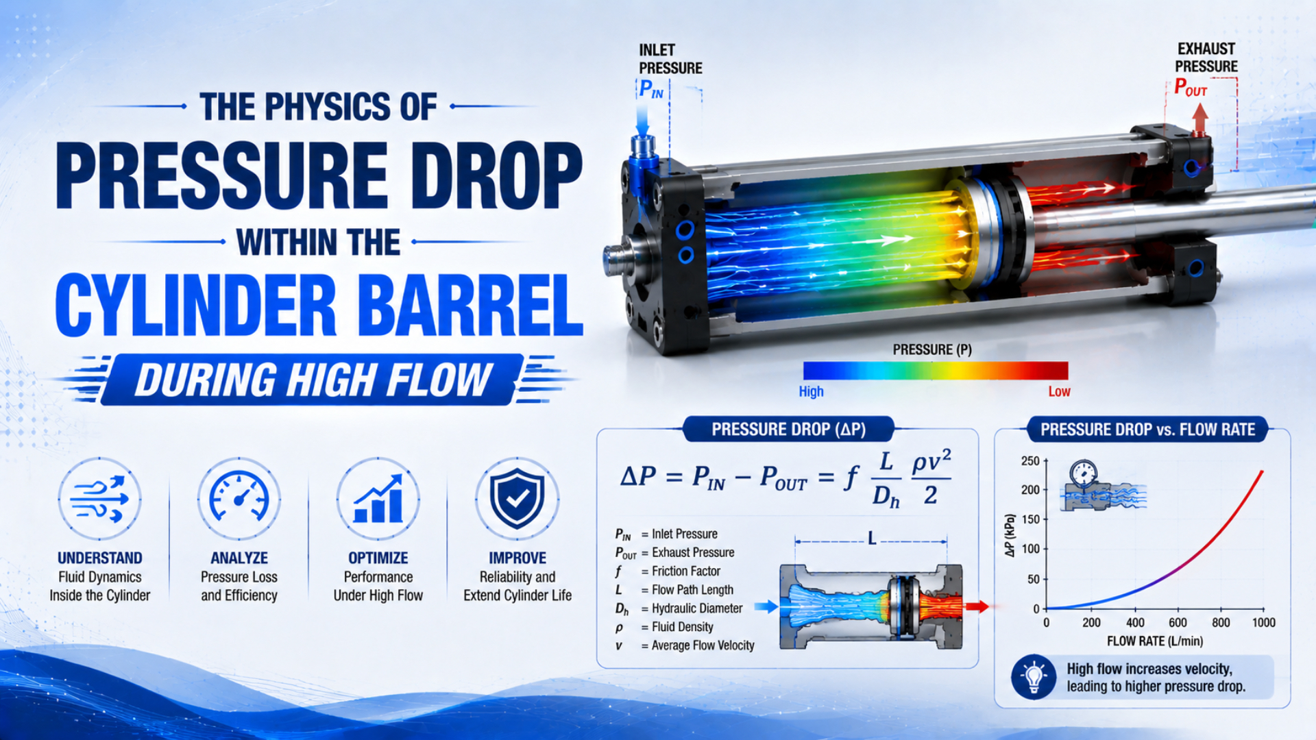
Pneumatic cylinder chamber pressure changes during fast motion, but not because air normally travels through the barrel like water through a pipe. A healthy double-acting cylinder has two sealed, variable-volume chambers. Air enters one chamber and leaves the other through ports, while the piston separates the two gas volumes.
The useful engineering question is therefore not “How much pipe friction occurs along the bore?” It is “How quickly can mass enter and leave each chamber while the piston changes their volumes?” That distinction explains pressure lag, reduced dynamic force, speed limits, exhaust backpressure, and end-of-stroke pressure spikes.
Key Takeaways
- ISO 6358 excludes cylinders from its steady-state component-flow method because they exchange energy with the gas.
- Model the barrel as 2 changing chambers, not as one through-flow pipe.
- Measure both port pressures during motion; a stopped-cylinder gauge cannot reveal dynamic force.
- Size the complete supply and exhaust paths from target stroke flow.
Is Pressure Really Dropping Along the Cylinder Barrel?
ISO 6358-1 defines steady-state flow testing for pneumatic components, but it explicitly excludes 2 examples that exchange energy with the gas: cylinders and accumulators (ISO 6358-1). A moving cylinder must instead be treated as a transient mechanical and thermodynamic system.
In a conventional double-acting cylinder, the piston seal prevents intentional flow from one chamber to the other. During extension, compressed air enters the cap-end chamber as the rod-end chamber exhausts. Retraction reverses those paths. The pressure in either chamber may be spatially nonuniform for a short time, particularly near a port or cushion restriction, but the barrel is not one continuous flow passage.
This makes the phrase pressure drop within the cylinder barrel easy to misread. Three different effects must be separated:
- Restriction loss: a simultaneous pressure difference across a valve path, tube, fitting, speed controller, port passage, cushion needle, or muffler while mass is flowing.
- Chamber pressure evolution: pressure rising or falling because gas mass and chamber volume are changing with time.
- Local transient gradients: short-lived pressure variation inside a chamber when the lumped, uniform-pressure assumption is no longer adequate.
Darcy-Weisbach remains useful for a sufficiently long, defined tube or constant-area passage when its assumptions and gas-density treatment are stated. It is not the governing equation for the whole cylinder chamber. The system pressure-drop troubleshooting guide covers the upstream network; this article stays inside the actuator boundary.
The decisive boundary is the piston seal. If appreciable air actually crosses it during a hold test, the problem is internal leakage, not desirable high-flow motion. If air reaches the chamber through a restrictive end-cap passage, the loss belongs to that passage even though the pressure sensor is mounted on the cylinder.
How Does Pneumatic Cylinder Chamber Pressure Change During a Stroke?
A double-acting-cylinder study sampled chamber pressure and displacement every 0.1 ms, tested source pressures of 200, 400, and 500 kPa, and repeated each experiment 45 times (Experimental Techniques, 2020). The synchronized traces show why pressure and position must be modelled together.
Let be piston position measured from the retracted end, the stroke, the full piston area, the rod-side annular area, and and the dead volumes at the two ends. The chamber volumes are:
During extension, increases and decreases. Even if the valve sends mass into chamber A continuously, its pressure does not have to equal the regulator setting: the newly admitted gas must fill a growing volume while doing work on the piston. Chamber B can remain above atmospheric pressure because its exhaust path is restricted.
For a first screening model with uniform temperature in a chamber, the ideal-gas mass balance can be written as:
Here, is absolute chamber pressure, is chamber volume, is absolute gas temperature, is the specific gas constant for air, and is net mass flow into the chamber. A positive adds mass; the second term accounts for compression or expansion caused by piston motion.
The constant-temperature form is useful for understanding direction and sensitivity, not for validating a high-speed design. A more complete model uses an energy balance with heat transfer and enthalpy carried by incoming and outgoing gas. The Simscape Pneumatic Piston Chamber likewise treats pressure, temperature, mass flow, and piston displacement as coupled states.
Dead volume matters most near the end of travel. A short movement can produce a large fractional volume change when the remaining chamber volume is small. That is why a cushion needle can create a rapid rod-end or cap-end pressure rise without any increase in barrel-wall friction.
How Does Dynamic Chamber Pressure Determine Available Force?
The same 2020 experimental study used 2 chamber-pressure sensors and a high-resolution position encoder to relate pressure histories to piston force, velocity, and acceleration (Experimental Techniques). Dynamic force therefore depends on both sides of the piston, not on the regulator gauge alone.
For a conventional single-rod cylinder, the effective areas are:
Here, is bore diameter and is rod diameter. Using chamber gauge pressures referenced to the same ambient pressure, the available axial force is:
In this expression, and are the instantaneous cap-end and rod-end gauge pressures. includes seal and guide friction, while represents the external resisting force. Use pascals and square metres for force in newtons, or keep one consistent customary unit system.
Suppose the cap-end port reads 5.0 bar gauge during extension while the rod-end port remains at 1.2 bar gauge because of meter-out restriction. The cylinder does not have a 5.0 bar effective pressure difference. The opposing chamber pressure subtracts force over the annular area. On a large-bore actuator, that backpressure can consume a substantial part of the dynamic margin.
This is also why a cylinder may pass a static force check and miss cycle time. After motion stops, chamber A may climb closer to supply pressure and chamber B may finish exhausting. The stopped reading hides the smaller differential that existed during acceleration and mid-stroke travel. Use the pneumatic cylinder force calculation guide for static sizing, then verify the moving pressures separately.
Where High-Flow Pressure Loss Actually Occurs
ISO 6358-1 characterizes fixed or variable component flow paths under steady-state conditions, while its 2026 amendment addresses measurement uncertainty (ISO 6358-1; Amendment 2:2026). Those tested component data belong at the restrictions around the cylinder, not across the moving chamber itself.
During extension, trace the active path in order: regulator, valve inlet, valve supply-to-work passage, fitting, tube, speed controller, cylinder port, chamber A, chamber B, opposite speed controller, return tube, valve work-to-exhaust passage, and muffler. Retraction uses different work ports and often different internal spool passages.
| Location | What creates the pressure difference | Best evidence |
|---|---|---|
| Filter and regulator | element loading, regulator droop, undersized body | dynamic inlet and outlet pressure at peak demand |
| Directional valve | effective flow area, spool position, internal turns | manufacturer flow curve, Cv/Kv, or ISO 6358 data |
| Tube and fittings | small ID, length, bends, reducers, couplers | measured end-to-end pressure plus verified ID and peak flow |
| Speed controller | intentional metering in one direction | needle setting, free-flow direction, pressure on both sides |
| Cylinder end-cap passage | port thread and internal drilled passage | pressure at the port and, if justified, an additional chamber tap |
| Cushion restriction | shrinking exhaust area near end of stroke | pressure and position trace through the cushion zone |
| Exhaust and muffler | return passage, contamination, insufficient area | chamber backpressure and pressure ahead of the muffler |
Does a low chamber pressure automatically mean the port is undersized? No. The supply pressure may already be collapsing at the valve inlet, or the exhaust side may be holding back the piston. Compare simultaneous points before assigning the loss to one component.
For the valve alone, use the pneumatic valve pressure-drop guide. For the transition from ordinary restriction loss to a mass-flow ceiling, see the cylinder choked-flow and speed guide.
How Should Dynamic Cylinder Pressure Be Measured?
The published cylinder test bench synchronized 2 chamber pressures with displacement at 0.1 ms intervals and repeated each condition 45 times (Experimental Techniques). A plant diagnosis needs less laboratory repetition, but it still needs simultaneous, time-resolved pressure and position rather than separate gauge observations.
Use pressure transducers with a range, overload rating, frequency response, temperature capability, and media compatibility suited to the circuit. Mount them close to the intended boundary. A sensor on the valve work port includes the loss of the downstream tube and fitting; a sensor at the cylinder port does not. Neither automatically measures the internal chamber if a narrow end-cap passage lies between the port and the gas volume.
In our experience, four synchronized signals settle most disputes quickly: valve-inlet pressure, cap-end port pressure, rod-end port pressure, and piston position or stroke-complete timing. Add a point ahead of the muffler only when the exhaust path remains ambiguous.
Follow this sequence:
- Record bore, rod, stroke, orientation, load, target time, valve model, tube ID and length, fittings, controllers, cushion setting, and mufflers.
- Establish the same initial position and dwell time before each test.
- Log extension and retraction separately at normal machine load.
- Compare pressures at the same instant, especially during acceleration, mid-stroke, and cushion entry.
- Change one restriction at a time and repeat the trace.
The shape of the trace is often more informative than its minimum value. A cap-end pressure that recovers gradually suggests flow cannot keep pace with increasing volume. A rod-end spike near the last part of travel points toward cushioning or exhaust restriction. An inlet pressure dip shared by both motion directions points upstream.
Sensor bandwidth matters. A slow electronic gauge can average away valve opening transients and end-cushion peaks. Long, narrow sensing tubes add pneumatic delay and damping. For acceptance work, document the sampling rate, transducer response, mounting connection, filtering, and time alignment with the position signal.
How Much Flow Does a Fast Stroke Require?
NIST defines 1 standard atmosphere as 101,325 Pa or 14.6959 psi and warns that standard gas-flow units can use different reference temperatures (NIST, updated 2025). A catalog L/min or SCFM value must therefore be tied to a stated reference condition.
For a first-pass estimate of one stroke’s normal-volume flow demand:
Here, is flow at the selected normal reference condition, is piston or annular area, is stroke, is target stroke time, is estimated average absolute chamber pressure during motion, and and are absolute temperatures.
Consider a 50 mm bore cylinder extending 500 mm in 0.5 s. Its swept volume is about 0.982 L, so the ideal chamber-condition flow is approximately 118 L/min. If average chamber pressure is estimated at 6 bar absolute and temperature is unchanged, the corresponding demand is about 698 normal L/min at 1.01325 bar absolute.
That result is not a valve guarantee. It omits dead volume, tube volume, leakage, temperature change, acceleration, load variation, cushion restriction, and the valve’s nonlinear compressible-flow curve. It does show why a fast, moderate-bore cylinder can outrun a seemingly generous fitting or valve.
If available flow is already known, use the Cylinder Speed Calculator as a separate first estimate. Do not use a straight-pipe pressure-drop calculator to represent changing cylinder chambers; apply it only to a defined upstream or exhaust tube segment.
A Measurement-First Fix Order for High-Flow Performance
CAGI’s pressure-drop guidance uses 10% from compressor discharge to point of use as a common well-designed-system target and cites about 20 ft/s as a distribution-piping velocity guideline (CAGI Pressure Drop Technical Brief). Those are plant-air references, not universal cylinder-port acceptance limits.
Start with the measured boundary that loses the most pressure during the failed motion. If the valve inlet collapses, a larger cylinder port will not repair the shared supply. If the valve inlet stays steady but chamber A lags badly, inspect the active valve path, tube, fittings, controller, and end-cap passage. If chamber B remains high, work on the exhaust side.
A safe correction order is:
- Confirm the required motion and force. Recheck bore, rod area, load, orientation, stroke time, and cushion energy.
- Restore maintenance condition. Replace contaminated filter elements and mufflers; verify regulator operation and lubricator requirements.
- Remove unnecessary restrictions. Eliminate reducers, undersized couplers, extra elbows, and long small-ID tubes where the machine design permits.
- Select the active valve paths. Use manufacturer flow curves or ISO 6358 conductance data for supply and exhaust, not the port thread alone.
- Set meter-out control deliberately. Meter-out often stabilizes motion, but the resulting backpressure must remain inside the force budget. The meter-in versus meter-out guide explains the control trade-off.
- Review end cushioning. A cushion needle is an intentional exhaust restriction near the end of travel. Use the pneumatic cushion-needle guide before opening it solely to gain speed.
- Reselect rather than machine. Never enlarge a pressure-bearing port or end-cap passage without the cylinder manufacturer’s approved drawing and procedure.
ISO 4414 provides general safety requirements for pneumatic systems and components (ISO 4414). Any change to pressure, stored air volume, exhaust behavior, cylinder speed, or end cushioning requires a new review of force, impact energy, component ratings, isolation, unexpected movement, and restart behavior.
A larger valve can expose the next bottleneck without fixing the cycle. The proof is not the new component’s catalog rating; it is a before-and-after pressure-position trace showing that the intended boundary changed and no new exhaust spike or impact problem appeared.
When Is a Uniform Chamber-Pressure Model Not Enough?
The 2020 cylinder experiment sampled every 0.1 ms, while contemporary actuator models couple time-varying chamber volume, mass flow, pressure, temperature, valve dynamics, tube delay, friction, and leakage (Experimental Techniques). The required model detail depends on the decision being made.
A lumped chamber model assumes pressure and temperature are spatially uniform inside each chamber at any instant. It is usually adequate for first-pass sizing, control simulation, and field diagnosis when chamber acoustic equalization is much faster than the mechanical event of interest and the port passage can be treated as a separate restriction.
This article uses compressibility only to explain high-flow pressure evolution. For trapped-air stiffness, position-dependent compliance, resonance, and closed-loop control, see the separate guide to air compressibility in pneumatic cylinder control.
Escalate the model or instrumentation when:
- the port jet, end-cap cavity, or cushion geometry is the design question;
- pressure sensors at the port and deeper chamber location disagree materially;
- very short strokes make dead volume and port volume dominant;
- valve switching, impact, or cushioning occurs on a similar timescale to pressure-wave travel;
- a long rodless-cylinder chamber or unusual internal passage challenges the uniform-pressure assumption;
- measured traces cannot be reconciled with verified valve data, friction, leakage, and load.
CFD can then resolve local velocity, temperature, and pressure fields, but it needs defensible boundary conditions and validation data. A detailed color contour is not evidence by itself. Match the simulation to measured port pressure, chamber pressure, piston position, mass flow, and thermal assumptions before using it to change a pressure boundary.
The practical hierarchy is simple: calculate demand, measure both chambers, isolate restrictions, and only then increase model fidelity. Most maintenance problems are solved before CFD becomes necessary.
Pneumatic Cylinder Pressure FAQs
ISO 6358-1 has defined steady-state component-flow testing since 2013, yet it excludes cylinders because moving boundaries exchange energy with the gas (ISO 6358-1). These 5 questions separate ordinary restriction loss, chamber pressure dynamics, force, measurement, and safe correction.
Is the pressure uniform everywhere inside a pneumatic cylinder chamber?
Not at every instant. Port jets, rapid valve switching, long chambers, and cushion restrictions can create local transient gradients. For many sizing and control tasks, each chamber is treated as one uniform pressure because internal equalization is fast relative to piston motion. Validate that assumption when events are extremely short or geometry is unusual.
Can I use Darcy-Weisbach to calculate pressure drop through the cylinder barrel?
Not as the main cylinder model. Darcy-Weisbach can estimate friction in a defined tube or constant-area passage when its assumptions are satisfied. A working cylinder chamber has a moving boundary, changing volume, heat transfer, and time-varying mass, so it requires mass and energy balances coupled to piston motion.
Why does cylinder force fall even when regulator pressure is stable?
The working chamber may remain below regulator pressure while it fills, and the exhausting chamber may retain backpressure. Available force comes from both instantaneous chamber pressures acting on different areas, minus friction and load. Measure cap-end and rod-end pressures during motion instead of relying on the regulator or stopped-cylinder reading.
Where should pressure sensors be installed for a high-speed cylinder test?
Start at the valve inlet and both cylinder ports, then synchronize those signals with piston position or stroke time. Add a sensor ahead of an exhaust muffler when backpressure remains unclear. Keep sensing connections short and document transducer bandwidth, sample rate, filtering, pressure reference, and exact measurement boundary.
Is enlarging the cylinder port a safe way to increase speed?
Not as an uncontrolled retrofit. Machining a threaded port or end-cap passage can weaken a pressure boundary, damage sealing geometry, and invalidate ratings. First locate the measured restriction. If the cylinder passage is truly limiting, select a manufacturer-approved high-flow option or a different cylinder rather than modifying it without engineering authorization.
Sources and technical references
- ISO 6358-1:2013, steady-state flow-rate characteristics of pneumatic components
- ISO 6358-1:2013/Amd 2:2026, measurement uncertainty
- Experimental Study of Double-Acting Pneumatic Cylinder
- NIST pressure and gas-flow unit conversions
- MathWorks Pneumatic Piston Chamber
- ISO 4414:2010, pneumatic system safety requirements
- CAGI Pressure Drop Technical Brief