

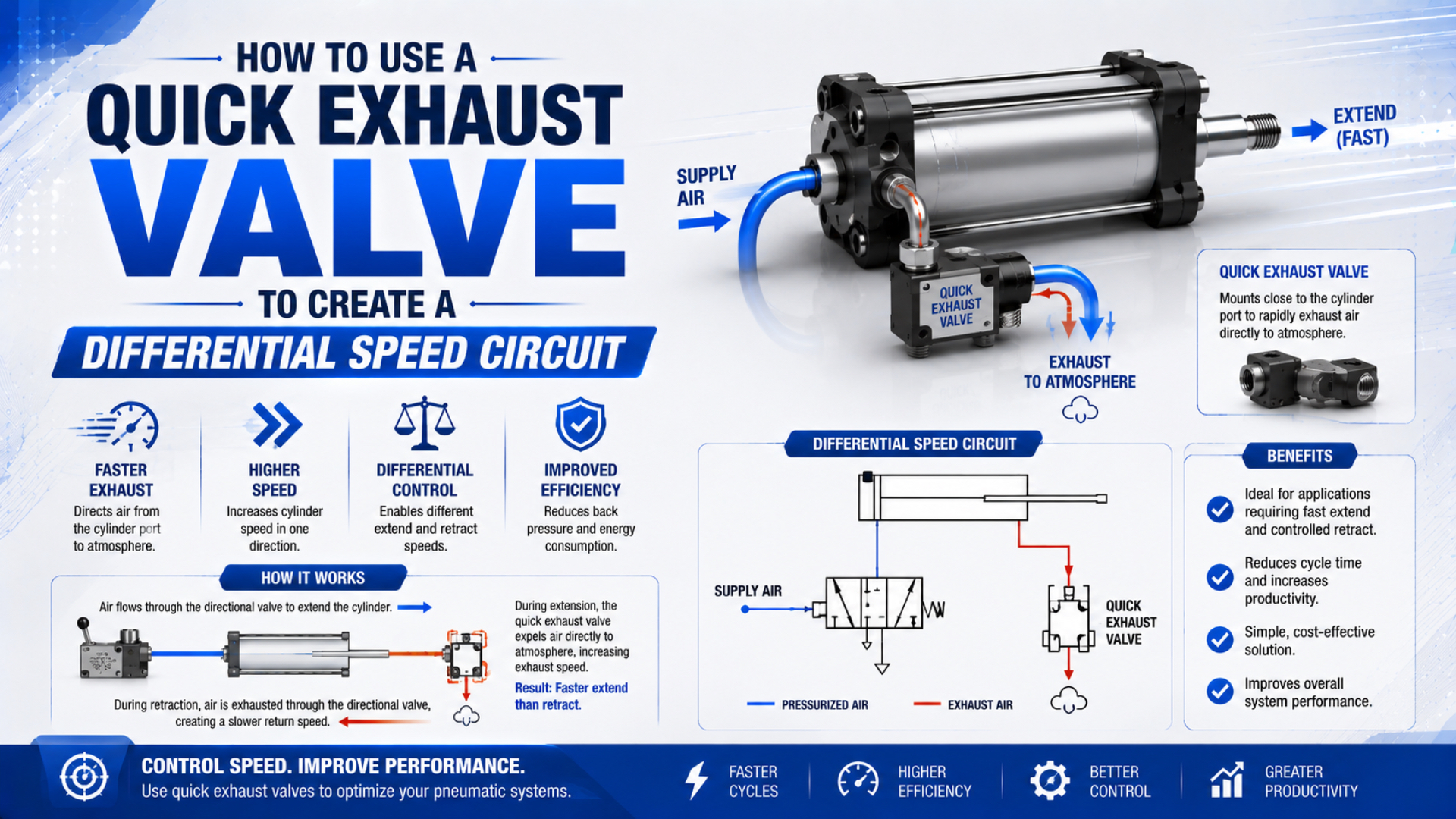
A quick exhaust valve differential speed circuit is a pneumatic arrangement that makes one cylinder stroke faster by venting the chamber that must empty during that stroke directly to atmosphere. Install the quick exhaust valve at that chamber’s cylinder port, not automatically at the rod end. Keep the opposite stroke under appropriate flow control, then verify dynamic pressure, stroke time, end cushioning, noise, and load behavior before releasing the machine.
Key Takeaways
- Port placement selects the fast stroke.
- A 3-port valve switches automatically.
- Flow data and tube volume set capacity.
- Before release, verify dynamic pressure, sensor timing, cushions, shock absorbers, load guidance, tooling, frame reactions, exhaust noise, and repeatability at the worst credible operating condition.
This guide focuses on building and commissioning the asymmetric circuit. For component construction, Cv terminology, and general selection, first review how a quick exhaust valve works. For the controlled stroke, the companion guide to meter-out cylinder speed control explains why exhaust back pressure can stabilize motion.
What Circuit Does a Quick Exhaust Valve Actually Create?
Festo identifies 3 functional ports in one SEU quick exhaust valve housing for local cylinder venting: supply 1, cylinder outlet 2, and exhaust 3. Supply air passes from 1 to 2; when pressure at 1 falls, the cylinder side vents from 2 to 3 through the silencer (Festo SEU, accessed 2026).
A quick exhaust valve is a self-actuating pneumatic valve, so it requires no coil, wire, PLC output, or separate pilot signal. The directional valve still decides which cylinder chamber receives pressure and which line connects to exhaust. The quick exhaust valve senses the resulting pressure difference and shortens the exhaust route for the chamber connected to its cylinder port. Differential speed means the two stroke directions intentionally run at different speeds; it does not mean the valve doubles force, reduces fill volume, or guarantees a fixed percentage improvement.
A three-state sequence follows:
- Supply: the directional valve pressurizes the quick exhaust inlet, the exhaust seat closes, and air flows to the cylinder chamber.
- Reversal: inlet pressure falls as the directional valve switches that line to exhaust.
- Local exhaust: higher cylinder-side pressure moves the internal poppet or diaphragm, closes the inlet path, and opens the large atmospheric exhaust.
Local exhaust does not create speed by adding energy. It removes a return-path restriction. If supply flow, load force, guide friction, cushion adjustment, or another restriction already limits the stroke, relocating the exhaust may produce little improvement.
Which Cylinder Port Determines the Fast Stroke?
Parker’s rapid-retraction example uses one quick exhaust valve close-coupled to the cylinder cap end, allowing that chamber to vent locally while a 4-way valve supplies the rod end. This placement rule is more useful than memorizing “quick exhaust equals fast return” (Parker Automation Valves, accessed 2026).
Follow the air leaving the cylinder. On a conventional double-acting cylinder, the cap-end chamber exhausts during retraction and the rod-end chamber exhausts during extension. The quick exhaust valve belongs on the chamber that must empty during the desired fast stroke.
| Required motion | Chamber being supplied | Chamber being exhausted | Typical quick exhaust location |
|---|---|---|---|
| Controlled extension, fast retraction | Rod end during retraction | Cap end during retraction | Cap-end cylinder port |
| Fast extension, controlled retraction | Cap end during extension | Rod end during extension | Rod-end cylinder port |
| Faster motion in both directions | Opposite chamber alternates | Opposite chamber alternates | One valve at each cylinder port, after a full risk review |
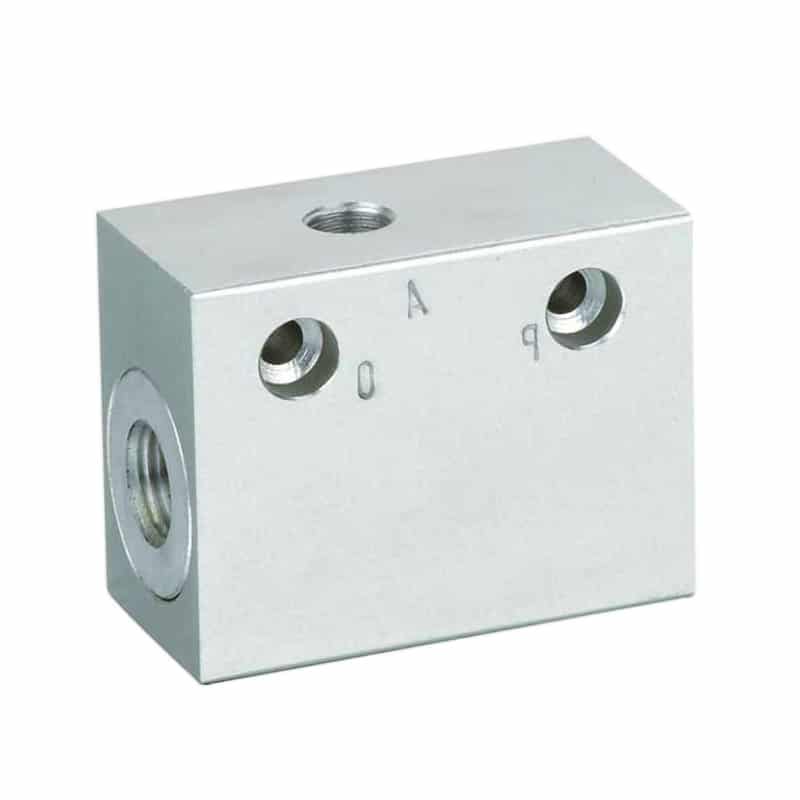
For the controlled direction, a suitable flow circuit is still necessary. With slow extension and fast retraction, a correctly oriented meter-out controller on the rod-end port can restrict rod-end exhaust during extension while allowing freer supply into the rod end during retraction. The cap-end quick exhaust valve then bypasses the long return path only during retraction. A vertical axis needs additional scrutiny: a gravity-assisted stroke can accelerate after exhaust restriction is removed, while the opposite direction remains load-limited. Evaluate load direction, piston area, pressure, stopping distance, and hose-failure consequences separately for each stroke.
How Should the Valve Ports and Flow Controls Be Connected?
Festo’s SEU range operates from 0.5 to 10 bar with compressed air and uses ports 1, 2, and 3 for supply, cylinder, and exhaust respectively. Those numbers are common but not universal, so the selected model’s symbol and body markings must govern the connection (Festo SEU, accessed 2026).
Depressurize and isolate every energy source before changing the circuit. Connect the directional valve’s working port to the quick exhaust inlet, connect the valve’s cylinder port to the target cylinder chamber with the shortest practical path, and leave the exhaust port open to a correctly sized silencer or approved exhaust duct. Never plug it.
Plumb by function, not appearance.
Use this connection checklist:
| Connection | Required check | Consequence of an error |
|---|---|---|
| Directional valve to quick exhaust inlet | Confirm manufacturer port marking and working pressure | Reversed ports can prevent switching or leak continuously |
| Quick exhaust cylinder port to actuator | Keep the fitting and tube short; support cantilevered hardware | Added volume delays pressure reversal and local exhaust |
| Atmospheric exhaust | Match silencer or duct flow capacity to exhaust rating | Back pressure removes the intended speed advantage |
| Opposite cylinder port | Orient the one-way flow control for the required controlled stroke | Wrong orientation can meter supply, exhaust, or both unexpectedly |
| Sensors and cushions | Confirm their operating range at the new velocity | The cylinder may arrive sooner or strike harder than the sequence expects |
Do not regulate speed by partially blocking an ordinary quick exhaust outlet unless the manufacturer approves that arrangement. A speed-exhaust controller integrates a designed exhaust restriction; a generic silencer or improvised needle may create enough back pressure to delay switching, cause chatter, or make the result load-sensitive. No single valve can overcome a small cylinder port, undersized fitting, collapsed tube, restricted speed controller, blocked silencer, or directional valve that fails to reduce inlet pressure quickly enough. Mark pressure-test points on both sides of the valve before commissioning.
Sizing the Exhaust Path From Target Stroke Time
SMC publishes ASV sonic-conductance values from 0.06 to 5.8 dm³/(s·bar), depending on body, port, tube, and flow direction. That span shows why thread size alone cannot establish exhaust capacity; compare the exact model’s OUT-to-exhaust data with the required operating point (SMC ASV, accessed 2026).
Start with the chamber that must empty during the fast stroke. Its geometric displacement is based on the effective piston area and stroke length. For a target stroke time, the average chamber-condition flow is:
is average displaced volume per unit time at chamber conditions, is cap-end piston area or rod-end annular area, is stroke, and is target stroke time. This is not yet normalized free-air flow and does not include acceleration, pressure decay, leakage, cushion travel, or valve response.
Tubing between the cylinder and quick exhaust valve adds volume that must change pressure before the valve can deliver its local-exhaust benefit:
is internal tube volume, is actual tube inside diameter, and is tube length between the cylinder and quick exhaust valve. Use consistent units. This relationship explains the “mount close” rule, but it does not replace the manufacturer’s compressible-flow selection method.
Compare supply and exhaust ratings separately. Festo’s SEU-1/4 lists nominal flow of 960 L/min from 1 to 2 and 1,100 L/min from 2 to 3, while the SEU-1/2 lists 4,560 and 4,020 L/min respectively. A larger nominal port does not prove that every exhaust path exceeds its supply path. A practical retrofit check compares three capacities: required chamber flow, the quick exhaust valve’s cylinder-to-exhaust rating, and the attached silencer or duct rating. The smallest effective path remains the bottleneck.
How Do Silencers, Tube Volume, and Back Pressure Change the Result?
Festo reports release-noise values of 83 to 86 dB for four SEU sizes when tested at 6 bar and 1 m, even with built-in silencers. Exhaust noise therefore needs both a flow-capacity check and a workplace-noise review; “silenced” does not mean quiet under every installation condition (Festo SEU, accessed 2026).
A silencer adds resistance as air accelerates through its porous element. Oil mist, water, pipe compound, dust, and icing can raise that resistance over time. If the cylinder gradually slows after a successful retrofit, compare dynamic cylinder-port pressure with the silencer installed, cleaned, and temporarily replaced by an approved equivalent rather than assuming the quick exhaust valve has failed. Back pressure also affects switching: SMC warns that residual inlet pressure, insufficient inlet-to-outlet pressure difference, or an inlet path smaller than the ASV can cause inadequate exhaust or vibration. A normal static gauge reading cannot clear those dynamic conditions.
The force balance shows why removing exhaust pressure changes motion:
is the accelerating force, the two pressure-area terms act on opposite sides of the piston, and the remaining terms oppose motion. A quick exhaust valve can reduce rapidly. That may increase acceleration even when supply pressure and nominal cylinder force are unchanged. For exhaust-noise selection, see the guide to pneumatic mufflers and flow restriction. For long remote lines, also check compressed-air pressure drop rather than treating the quick exhaust valve as a cure for every pressure problem.
Commissioning the Differential Speed Circuit
SMC states that ASV310F, ASV410F, and ASV510F flow is approximately twice that of control by a speed controller, but limits the statement to those models and its comparison. Commissioning must measure the installed machine instead of turning that product result into a universal speed promise (SMC ASV, accessed 2026).
Begin with reduced speed or pressure under the machine builder’s approved procedure. Confirm port orientation and unobstructed exhaust before cycling. Then adjust the controlled direction, increase the fast direction in small steps, and observe the complete load path rather than watching only the piston rod.
Record it before tuning.
Use the same baseline before and after the change:
| Measurement | Why retain it |
|---|---|
| Extension and retraction time, measured separately | Confirms that only the intended stroke changed |
| Driving- and exhausting-chamber pressure during motion | Shows whether supply or exhaust remains restrictive |
| Time and velocity at cushion entry | Connects the speed change to stopping demand |
| End-sensor confirmation, rebound, and dwell | Detects timing or end-position instability |
| Exhaust noise at a defined location and condition | Makes silencer and workplace-noise comparisons repeatable |
| Load, tooling, pressure, temperature, and silencer model | Preserves the test configuration for later diagnosis |
Faster travel increases kinetic energy with the square of velocity. The cylinder cushion, external shock absorber, mounting, guide, tooling, and frame must accept the new stopping event. Use the cylinder cushion-energy workflow before approving a large speed increase. In our experience, the most revealing commissioning trace is pressure in the chamber connected to the quick exhaust valve. A fast drop followed by a smooth stop supports the intended sequence. A slow decay, oscillation, or high residual pressure points to switching, silencer, tubing, or cushion interactions that a stopwatch alone cannot identify.
Release the machine only when both stroke directions remain repeatable at the worst credible load and cycle rate, every sensor confirms in the permitted window, stopping produces no hard impact or rebound, and the circuit stays within the valve, cylinder, silencer, tubing, and machine ratings.
What Fault Patterns Reveal an Incorrect Quick Exhaust Circuit?
SMC lists 3 primary conditions behind insufficient exhaust or vibration in its ASV precautions: inlet-side residual or back pressure, differential pressure below the minimum, and an inlet-side effective area smaller than the ASV path. Diagnose those conditions before replacing the valve (SMC ASV, accessed 2026).
| Observed behavior | Likely circuit cause | Verification |
|---|---|---|
| No meaningful speed change | Another path limits flow, or the selected chamber is not the target exhaust chamber | Compare dynamic pressures and trace the fast-stroke air path |
| Continuous leakage from exhaust | Ports reversed, damaged seat, contamination, or insufficient inlet pressure | Check body symbol, pressure sequence, and seat condition |
| Chatter or vibration | Pressure differential is unstable or exhaust is restricted | Measure both valve-side pressures and inspect the silencer |
| Fast stroke ends with a hard impact | Exhaust restriction was removed without checking stopping energy | Reduce speed and review cushion or external-stop capacity |
| Speed falls after repeated cycles | Silencer contamination, temperature change, supply sag, or cushion drift | Repeat measurements at sustained operating temperature |
| Opposite stroke also changes | Flow-control orientation or supply path was altered during retrofit | Trace free-flow and metered directions through each check valve |
Do not infer energy savings from a faster exhaust. The cylinder still fills a chamber for each powered stroke, and the quick exhaust valve releases that air closer to the actuator. Any energy change must be measured from actual pressure, volume, leakage, cycle count, and compressor performance. If the machine needs accurate intermediate positioning, electronically commanded speed profiles, or load-independent velocity, a self-actuating quick exhaust valve is the wrong control element. Review proportional flow-control valve behavior instead.
Quick Exhaust Valve Differential Speed Circuit FAQs
Festo’s four SEU sizes cover nominal 2-to-3 exhaust flows from 390 to 4,020 L/min, while SMC’s ASV family spans several body and tube sizes. Those ranges show why FAQ answers must remain conditional on the selected valve, cylinder, circuit, and load rather than promising one universal speed gain (Festo; SMC, accessed 2026).
Where should I install a quick exhaust valve for fast retraction?
Install it at the chamber that exhausts during retraction, normally the cap-end port of a conventional double-acting cylinder. Connect the directional-valve line to the quick exhaust inlet and keep the cylinder-side connection short. Confirm the selected valve’s body markings because port numbers and physical layouts can vary by manufacturer.
Can a quick exhaust valve make extension faster instead?
Yes. Extension requires the rod-end chamber to exhaust, so a quick exhaust valve at the rod-end cylinder port can shorten that path. The cap end must still receive adequate supply flow. Check rod-end exhaust capacity, load direction, cushioning, sensor timing, and stopping energy before accepting the faster extension stroke.
Should the flow control go before or after the quick exhaust valve?
It depends on which stroke needs control and which product is selected. A conventional meter-out controller often belongs at the opposite cylinder port for the controlled stroke. Do not improvise a restriction on the quick exhaust outlet unless the manufacturer permits it; use a designed speed-exhaust controller when local exhaust adjustment is required.
Does a quick exhaust valve reduce compressed-air consumption?
Not inherently. It changes where one chamber exhausts, but it does not eliminate the air used to fill that chamber. Consumption may change if the retrofit also changes pressure, stroke frequency, leakage, or cycle logic. Calculate and measure those variables separately instead of treating faster exhaust as an energy-saving device.
Why did the quick exhaust valve fail to increase cylinder speed?
Often, the exhaust path is not the limiting element. Check cylinder-port pressure during motion, valve orientation, inlet pressure decay, silencer restriction, fitting and tube size, directional-valve capacity, cushion setting, load force, and guide friction. SMC also warns that inadequate differential pressure can prevent reliable local exhaust switching.
Sources and technical references
- Festo, SEU Quick Exhaust Valves, port paths, mounting, pressure, nominal flow, and release-noise data; accessed 2026-07-22.
- Parker, Quick Exhaust and Shuttle Valve Applications, rapid-retraction circuit placement, cap-end exhaust routing, and the reason local exhaust capacity can reduce dependence on a large central 4-way valve; accessed 2026-07-22.
- SMC, ASV Series Speed Exhaust Controller, model-specific flow data, comparison, and switching precautions; accessed 2026-07-22.
- ROSS Controls, 18 Series Quick Exhaust Valves, 3/2 operation, installation position, port sizes, Cv data, and troubleshooting; accessed 2026-07-22.