

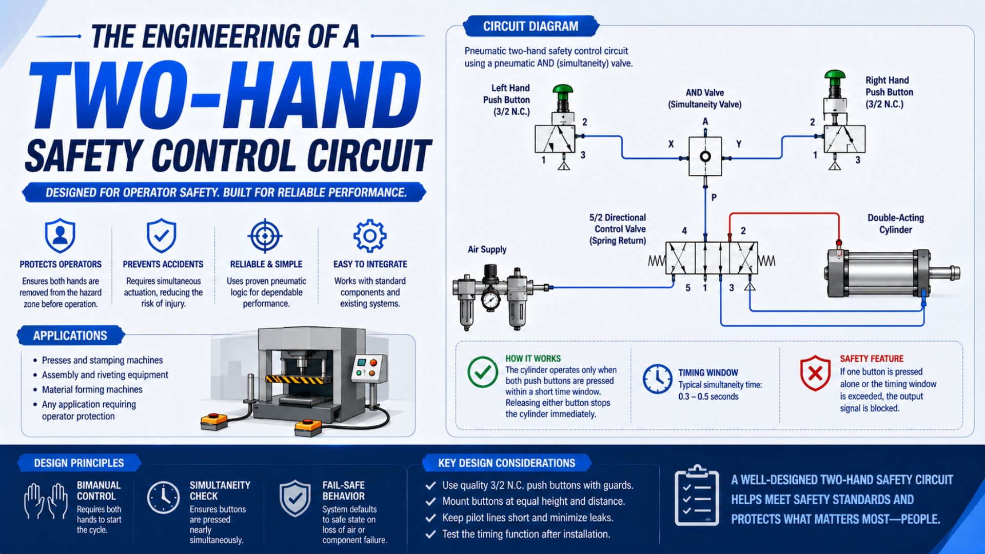
A two-hand safety control circuit is ready for service only after the installed machine passes its specified state, timing, restart, and fault-response tests. Pressing two buttons during a normal cycle proves very little. Commissioning must show what happens when one input is early, late, held, lost, or faulted and when the pneumatic output does not respond as commanded.
This article is a commissioning and fault-injection guide. For device types, safeguarding limits, two-hand control versus two-hand trip, and safety-distance principles, start with the pneumatic two-hand control overview. For Performance Level design, use the separate ISO 13849 pneumatic safety-circuit guide.
Key Takeaways
- ISO 13851 defines three THCD types but protects only the person using the device.
- Test every permitted state and every prohibited restart path.
- Measure the installed output, pressure, and hazardous motion, not only relay status.
- Inject faults under a controlled validation plan, never with a person exposed to the hazard.
What Must Be Frozen Before Commissioning Begins?
ISO 13851:2019 defines three functional THCD types but does not select one for a specific machine. Commissioning must therefore start with an approved safety-function specification that identifies the selected type, exposed person, hazard, safe state, required Performance Level, timing behavior, and machine-specific acceptance limits (ISO 13851, confirmed 2024).
Do not begin by adjusting button timing or valve flow. First freeze the documents that define what the system must do. A commissioning team cannot produce a defensible pass result when the required behavior changes during the test.
The minimum input package should contain:
- the current risk assessment and applicable type-C machine standard;
- the safety-function specification and required Performance Level, or PLr;
- the selected THCD type and exact device manual;
- electrical and pneumatic schematics with revision numbers;
- safety-controller program and checksum;
- output-valve safety manual, feedback method, and permitted accessories;
- expected response to release of either hand, reset, power loss, and air loss;
- measured or specified stopping and closing limits at the hazard;
- a fault list, test method, acceptance criteria, and restoration method;
- names and roles of the validator, test witness, and person authorizing release.
A commissioning acceptance criterion is a measurable condition that separates pass from fail before the test begins. “The machine stops safely” is not enough. State the maximum residual movement, pressure threshold, output state, permitted response time, sensor combination, and restart behavior that will be accepted.
ISO 12100 supplies the risk-assessment framework that precedes this work, while ISO 13849-1 supplies the control-system design method. Neither standard assigns a universal PLr or safe state to every two-hand application (ISO 12100, confirmed 2022; ISO 13849-1, 2023).
If the specification cannot answer what motion, pressure, or stored energy is allowed after either hand is released, stop. That is a design gap, not a commissioning adjustment.
Which State Table Should the Circuit Pass?
A two-hand device has two intentional hand inputs, yet validation needs more than the four Boolean input combinations. ISO 13851 also addresses prevention of defeat, fault avoidance, and verification. The state table must include timing order, held-input behavior, release behavior, reset, and restoration of power or air (ISO 13851, confirmed 2024).
Build the state table from the approved safety-function specification. The example below is a test framework, not a substitute for the selected THCD manual or machine standard.
| Test state | Input A | Input B | Additional condition | Expected result |
|---|---|---|---|---|
| S0 ready | released | released | safety conditions satisfied | output remains off and a new demand is permitted |
| S1 A only | actuated | released | any duration | safety output remains off |
| S2 B only | released | actuated | any duration | safety output remains off |
| S3 valid demand | actuated | actuated | synchronization requirement satisfied | output may turn on only if all other safety conditions are true |
| S4 late second input | actuated | actuated | synchronization requirement not satisfied | output remains off; both inputs must return to the required restart state |
| S5 one hand released | released | actuated, or reverse | during the required control period | output changes to the specified safe state and machine response stays within limits |
| S6 held-input retry | actuated | released then re-actuated, or reverse | one input never returned to ready | no new hazardous cycle is permitted |
| S7 restoration | actuated or both actuated | actuated or released | electrical power or air returns | no unexpected hazardous restart |
Record both the command and the observed result. A safety-controller bit may turn off while a valve remains shifted, pressure remains trapped, or the mechanism continues moving. The acceptance record needs evidence from the complete input, logic, output, and machine-response chain.
The state names should appear in the test procedure, controller diagnostics, and final report. That common naming makes a failed test traceable. It also prevents a vague note such as “button test passed” from hiding which timing or restart path was actually checked.
The prohibited states often reveal more than the valid state. A correct two-button start can pass even when anti-tie-down or restart prevention is defective. Commissioning should spend at least as much attention on commands that must not produce an output as on the one command that may produce it.
How Should Simultaneity, Anti-Tie-Down, and Anti-Repeat Be Tested?
OSHA requires concurrent operation and anti-repeat behavior for specified mechanical-power-press applications, while ISO 13851 defines device behavior by THCD type. Neither source supports copying an arbitrary timing value into every machine. Test the exact synchronization window and restart sequence stated by the selected device and safety-function specification (OSHA 1910.217; ISO 13851).
Use a controlled input generator, safety-controller trace, or instrumented actuators when manual timing cannot produce repeatable boundary tests. Test values below, at, and above the permitted synchronization limit. Record input transition timestamps and the safety output. Do not infer the actual timing window from whether a cylinder happened to move.
Run these sequences in both A-first and B-first order:
- Actuate the second input well inside the permitted interval and confirm that a valid output is possible.
- Repeat at the documented boundary using equipment with adequate time resolution.
- Actuate the second input outside the permitted interval and confirm that the output remains off.
- Release only one input, press it again while the other remains held, and confirm that no new cycle begins.
- Hold one input before reset or mode entry, then operate the second input.
- Hold both inputs through reset, power restoration, and air restoration.
- Release both inputs, restore the required ready state, and confirm that the next valid demand follows the documented sequence.
Anti-tie-down and anti-repeat are related but not interchangeable. Anti-tie-down is the behavior that prevents a held or defeated input from combining with repeated operation of the other input. Anti-repeat is the behavior that prevents another hazardous cycle without the required release and new actuation sequence. The test report should identify which requirement each sequence verifies.
If a configurable safety controller implements the timing, verify parameter limits, access control, download record, and checksum. If a dedicated THCD module implements it, record the exact part number, revision, supply conditions, and diagnostic indication. In either case, test the installed signals. A catalog claim doesn’t prove that field wiring or tubing matches the evaluated arrangement.
Fault-Injection Planning and Test Control
ISO 13849-2:2012 requires validation by analysis and testing of the specified safety functions, Category, and achieved Performance Level. Fault injection belongs inside that planned validation process. It must use identified faults, defined acceptance criteria, authorized personnel, controlled energy, and a documented method for restoring the machine (ISO 13849-2).
Never improvise faults on a production machine with a person inside the hazard zone. Establish barriers, mechanical restraints, test mode, energy limits, and emergency recovery before changing a safety input or output. The test leader should be able to stop the activity whenever the observed machine state differs from the procedure.
For every fault, document:
- test ID and safety requirement being challenged;
- exact conductor, tube, valve, sensor, or software signal affected;
- machine mode, load, position, pressure, temperature, and speed;
- safe method used to simulate the fault;
- expected diagnostic indication and fault reaction;
- whether the current cycle, next cycle, or both must be inhibited;
- expected output-valve, downstream-pressure, and mechanical response;
- restoration steps and checks before the next test;
- actual result, evidence file, witness, date, and disposition.
Inject one planned fault at a time unless the risk assessment and validation plan explicitly require accumulated-fault testing. Uncontrolled combinations make diagnosis difficult and may create a hazardous state the procedure never anticipated. After each test, confirm that temporary jumpers, plugs, software forces, restricted tubes, and simulated feedback signals have been removed.
In our experience reviewing validation packages, the most dangerous test artifact is an undocumented temporary bypass. A bright, numbered test lead and a signed restoration checklist are simple controls, but they prevent a successful fault test from leaving the machine in a defeated condition.
Input and Logic Fault-Injection Matrix
ISO 13849-1 applies to electrical, pneumatic, hydraulic, mechanical, and software elements in high-demand or continuous-mode safety functions. A two-hand circuit can therefore fail through wiring, tubing, actuator mechanics, logic parameters, or shared supplies. The fault list must follow the implemented technology rather than assuming every system is purely electrical (ISO 13849-1, 2023).
Select faults from the design’s failure analysis and the component safety manuals. The following matrix provides test prompts; it does not declare every listed fault applicable or safely injectable.
| Fault prompt | What the test challenges | Evidence to capture |
|---|---|---|
| Input A open circuit or lost pneumatic signal | single-channel loss | output state, diagnostic, restart inhibition |
| Input B open circuit or lost pneumatic signal | opposite channel independence | same evidence with channels reversed |
| Input short to supply or pressure held on | stuck active input | anti-tie-down and fault detection behavior |
| Input short to common or exhaust | stuck inactive input | no false output and correct diagnostic |
| Cross-short or crossed tubes, where credible | channel independence and discrepancy monitoring | whether one action can satisfy both channels |
| Actuator mechanically held | defeat resistance | no repeat cycle from the free actuator |
| Input timing outside the permitted window | synchronization monitoring | timestamps and rejected output |
| Timing parameter altered | configuration control | access protection, checksum, diagnostic, test result |
| Lost input-module supply | de-energization behavior | output and restart state |
| Reset input held or faulted | reset monitoring | reset does not initiate motion or mask an input fault |
Do not create a short circuit unless the component instructions and test setup make that method safe. A controller’s built-in test pulse or certified fault-insertion unit may be preferable. Pneumatic inputs may require a manufacturer-approved blocking, venting, or signal-holding method rather than pinching tubes or installing unlisted restrictions.
Test channel symmetry. If the A-channel fault is detected but the corresponding B-channel fault is not, investigate wiring, diagnostic configuration, and common-cause assumptions. A pair of inputs isn’t redundant merely because two buttons are visible on the console.
Output and Pneumatic Fault-Injection Matrix
Festo describes pneumatic two-hand control as simultaneous actuation that produces an output signal. That signal is not the safe state itself. Commissioning must test the downstream valve, pressure path, actuator, load, and feedback because one failed output element or restricted exhaust can change the machine response (Festo Pneumatic Safety).
Begin with the output failure modes identified by the valve safety manual and circuit analysis. Some faults should be simulated through feedback or a test fixture instead of physically jamming a valve. The method must not damage a certified component or create an uncontrolled movement.
| Fault prompt | Required engineering question | Installed evidence |
|---|---|---|
| One output channel does not switch | Does the remaining architecture maintain the specified safety function? | controller output, valve feedback, pressure, motion |
| Valve feedback remains in the previous state | Is the discrepancy detected within the required time? | feedback trace, diagnostic code, next-cycle inhibition |
| Exhaust path restricted to the credible limit | Does pressure decay and motion remain within acceptance limits? | downstream pressure curve and hazardous movement |
| Silencer blocked or wrong accessory fitted | Does the documented configuration detect or tolerate the restriction? | part number, pressure trace, test result |
| Minimum and maximum permitted supply pressure | Does the safe response remain valid across the allowed range? | port pressure, valve state, stopping result |
| Air supply lost and restored | Can pressure restoration initiate movement? | command states, pressure rise, actuator position |
| Downstream tube fails or leaks | Does the load move, release, or fall? | load state and independent restraint response |
| Position or pressure feedback is forced wrong | Does plausibility logic detect the discrepancy? | sensor values, diagnostic, output behavior |
| Gravity or spring load acts after venting | Is exhaust actually the safe state? | measured movement and holding-device state |
The safe pneumatic response may be block, exhaust, stop and hold, controlled return, or a combination. Immediate venting is not universally safe. A vertical cylinder can descend and a clamp can release a workpiece. Use the safety exhaust valve integration guide and cylinder rod-lock guide when those functions form part of the risk reduction.
Valve feedback proves a valve element reached a monitored state. It does not prove pressure at the hazard fell fast enough or that hazardous motion stopped. The validation trace must extend beyond the monitored valve to the physical variable that can injure someone.
Measuring the Installed Machine Response
OSHA’s mechanical-power-press rule uses a hand-speed constant of 63 inches per second with measured stopping or closing time for specified two-hand safeguards. The broader lesson is that safety distance depends on installed machine response, not a relay or valve catalog time (OSHA 1910.217).
Time-correlate the events that define the safety function:
- transition of hand input A and hand input B;
- safety-logic decision and output command;
- output-valve feedback or monitored element position;
- downstream pressure at the relevant zone;
- actuator, slide, clamp, or tooling movement;
- achievement of the specified safe-state threshold.
Use measuring equipment with enough resolution and accuracy for the acceptance limit. Record calibration status, sample rate, sensor range, trigger method, and signal scaling. A phone video may help explain an event, but it is not a substitute for traceable timing and motion data when the limit is close.
Measure the worst credible condition, not only a convenient empty cycle. Relevant variables can include maximum load, highest speed, minimum and maximum supply pressure, warm and cold operation, worn brake condition, longest allowed tube, permitted silencer, restricted exhaust, unfavorable cylinder position, and gravity direction.
ISO 13855:2024 covers positioning of two-hand control devices and other safeguards relative to human approach. Use the applicable standard and type-C requirements for the actual machine. Do not reuse the OSHA mechanical-press formula or a generic 500 ms figure for an unrelated pneumatic fixture (ISO 13855, 2024).
Store raw traces as well as the summarized pass result. A report should let a reviewer identify the safety demand, output change, pressure response, mechanical response, and acceptance threshold on the same time base.
How Should Reset, Power Restoration, and Mode Changes Be Tested?
OSHA 1910.217 requires release of all operators’ hand controls before an interrupted stroke can resume in specified press controls. ISO 13849-1 treats restart and safety-function behavior as part of the complete control design. Commissioning must test reset, power cycling, air restoration, and mode changes as distinct events (OSHA 1910.217; ISO 13849-1).
A reset should acknowledge a safe condition and permit a later command. It should not itself initiate hazardous motion. Verify that principle with the hand inputs released, one held, both held, and each relevant feedback signal correct or incorrect.
Test at least these transitions:
- controller power off and on with neither hand actuator pressed;
- power restored with one actuator held;
- power restored with both actuators held;
- air restored before electrical power and in the reverse order;
- reset operated while an input remains active;
- reset operated while valve feedback is discrepant;
- automatic-to-manual and manual-to-automatic mode changes;
- return from emergency stop;
- return from a guard or external safety demand;
- communication loss and recovery where networked safety is used.
Record whether the machine remains stopped, whether pressure rises, whether an actuator moves, and what deliberate action is required before a new cycle. “No output bit” is insufficient if restoring air can shift a spring-return valve or move a gravity-loaded mechanism.
Emergency stop and two-hand control are separate safety functions. ISO 13850 defines the emergency-stop function independently of the energy technology. Do not use a successful emergency-stop test to close a failed two-hand-control requirement, or vice versa (ISO 13850, confirmed 2020).
Why Is Lockout/Tagout a Separate Test Boundary?
OSHA 1910.147 explicitly includes pneumatic energy and requires covered servicing work to address unexpected energization, startup, and stored-energy release. A two-hand device or safety relay is an operational safeguard, not automatically an energy-isolating device. Commissioning must keep safety-function testing separate from servicing isolation verification (OSHA 1910.147).
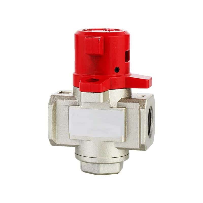
A lockable manual supply-and-vent valve can support an energy-control procedure when the device, installation, stored-energy controls, and verification steps meet the applicable requirements. Its presence does not establish the Performance Level of an automatic safety function. Likewise, pressing an emergency stop or removing a safety output does not automatically isolate every energy source.
When fault injection requires entering a hazard zone, changing tubing, restraining a valve, or touching a load, apply the site’s authorized isolation procedure. Identify pneumatic, electrical, mechanical, gravitational, spring, vacuum, hydraulic, and thermal energy. Relieve, disconnect, block, or restrain stored energy, then verify isolation before work begins.
After the modification is complete, remove tools and temporary test devices, restore guards, check that people are clear, and follow the authorized return-to-service procedure. The next functional test begins only after the machine has been returned to its defined test configuration.
The manual and mechanical valve selection guide explains ordinary valve functions. Do not credit an ordinary manual valve as a safety-rated isolating device or THCD input unless its documentation supports that exact use.
What Evidence Makes the Validation Record Auditable?
ISO 13849-2 requires validation of the specified safety functions, Category, and Performance Level by analysis and testing. A pass/fail checklist alone cannot show what configuration was tested. The final record must link each requirement to a method, measured result, fault response, evidence file, and approved disposition (ISO 13849-2, 2012).
Use one row per test rather than one row per component:
| Record field | Required content |
|---|---|
| Safety function | identifier, description, hazard, safe state, PLr |
| Requirement | exact state, timing, motion, pressure, or restart criterion |
| Configuration | machine serial number, drawing revisions, program checksum, device revisions |
| Test conditions | mode, pressure, load, speed, position, temperature, accessories |
| Test action | normal command or exact injected fault and method |
| Expected result | diagnostic, output, pressure, motion, restart behavior |
| Actual result | measured values and observations, not only “pass” |
| Evidence | trace, photograph, video, controller log, instrument file, calibration reference |
| Restoration | temporary changes removed and normal configuration verified |
| Disposition | pass, fail, deviation, corrective action, retest reference |
| Approval | tester, independent reviewer where required, date, signatures |
Keep the calculation and validation records aligned. If valve type, controller program, tube size, silencer, supply pressure, moving load, brake, tooling, or safe-state definition changes, review which analyses and tests are no longer valid. Configuration control is part of the evidence.
Before releasing the machine, reconcile every failed or interrupted test. An unexplained “pass after adjustment” is not closure. Record what changed, why the change is acceptable, which documents were revised, and which regression tests were repeated.
ANSI B11.19-2019 (R2024) covers performance requirements for the design, installation, operation, and maintenance of safeguarding and other risk-reduction measures. For North American machinery, use it together with the applicable machine-specific B11 standard and legal requirements rather than treating one generic checklist as certification (ANSI B11.19).
When Must Testing Stop and Return to Engineering?
ISO 12100 requires risk reduction to be assessed and verified across the machinery life cycle. Commissioning cannot approve a safety function by tuning around an undefined hazard, unstable stopping result, or failed fault reaction. When acceptance criteria cannot be met consistently, testing stops and the design returns to engineering (ISO 12100).
Stop testing when:
- the safe state is missing, contradictory, or changes between documents;
- a fault produces unexpected hazardous motion or load release;
- a temporary bypass cannot be positively identified and controlled;
- measured stopping or pressure-decay results exceed the limit;
- results vary beyond the permitted tolerance across load or pressure conditions;
- valve, controller, or THCD documentation does not cover the installed configuration;
- the achieved PL calculation depends on unverified component data;
- a diagnostic fails to inhibit the cycle required by the specification;
- restoring power or air creates unexpected movement;
- testing would require exposing a person to an uncontrolled hazard;
- the test configuration no longer matches the released drawings and software.
Do not hide a design failure by increasing a controller delay, reducing machine speed, moving buttons, or adding an operator instruction without updating the risk assessment and validation basis. A modification may be a valid solution, but it creates a new configuration that must be reviewed and retested.
For quotation or technical review, provide the safety-function specification, selected THCD type, circuit drawings, PLr, valve data, load and pressure conditions, timing limits, fault list, and required evidence through the technical contact page.
Two-Hand Safety Circuit Commissioning FAQs
ISO 13851 defines three THCD types, while ISO 13849-1 does not prescribe one universal PLr. These answers therefore focus on installed validation and documentation. The selected device manual, machine risk assessment, applicable type-C standard, and local legal requirements remain the controlling sources.
Can a Normal Two-Button Cycle Prove the Circuit Is Safe?
No. It proves only that one intended command produced an output under the tested conditions. Validation must also challenge early, late, held, released, and faulted inputs; output and feedback discrepancies; power and air restoration; and the physical machine response. The acceptance criteria must come from the approved safety-function specification.
Must Both Buttons Always Be Pressed Within 500 ms?
Do not apply 500 ms as a universal machine value. The permitted synchronization behavior depends on the selected THCD type, product instructions, applicable standard, and safety-function specification. Test below, at, and above the documented boundary in both A-first and B-first order, then record input and safety-output timestamps.
Can Fault Injection Be Performed on a Running Production Machine?
Only under a controlled, authorized validation procedure that prevents exposure to the hazard. Barriers, restraints, test mode, energy limits, recovery steps, and qualified personnel must be defined before injecting a fault. If the work requires entering the hazard zone or altering energy paths, apply the site’s isolation procedure.
Does Valve Feedback Prove the Machine Reached a Safe State?
No. Feedback can show that a monitored valve element reached a position, but pressure may remain trapped and the mechanism may continue moving. Measure the physical acceptance variable named by the safety function, such as hazardous travel, stopping time, downstream pressure, clamp state, or load restraint.
How Often Must the Two-Hand Circuit Be Retested?
There is no universal daily, monthly, or annual interval for every circuit. Set inspection and functional-test intervals from the risk assessment, component instructions, use frequency, diagnostic design, environment, machine-specific standard, legal requirements, and failure history. Revalidate affected requirements after hardware, software, tooling, pressure, speed, or load changes.
Where Do the Validation Requirements Come From?
The sources below define complementary boundaries: ISO 13851 addresses THCD design and selection; ISO 13849 covers safety-related control design and validation; ISO 13855 covers safeguard positioning; OSHA rules apply to specified US press and energy-control situations. None is a substitute for the machine risk assessment or applicable type-C standard.
- ISO 13851:2019. Two-hand control device principles, three functional types, prevention of defeat, selection, and verification. Confirmed 2024; accessed July 22, 2026.
- ISO 13849-1:2023. Design and integration method for safety-related control-system parts across electrical, pneumatic, hydraulic, mechanical, and software technologies. Accessed July 22, 2026.
- ISO 13849-2:2012. Validation of safety functions, Categories, and Performance Levels by analysis and testing. Current published edition pending revision; accessed July 22, 2026.
- ISO 12100:2010. Machinery risk-assessment and risk-reduction principles. Confirmed 2022; accessed July 22, 2026.
- ISO 13855:2024. Positioning of safeguards, including two-hand control devices, relative to human approach. Accessed July 22, 2026.
- ISO 13850:2015. Emergency-stop function principles independent of energy technology. Confirmed 2020; accessed July 22, 2026.
- OSHA 29 CFR 1910.217. US mechanical-power-press requirements for specified two-hand controls and trips, including concurrent operation, anti-repeat, and safety distance. Accessed July 22, 2026.
- OSHA 29 CFR 1910.147. Control of hazardous energy, including pneumatic energy, during covered servicing and maintenance. Accessed July 22, 2026.
- ANSI B11.19-2019 (R2024). Performance requirements for safeguarding and other risk-reduction measures. Accessed July 22, 2026.